AY-ZP35PR SERVICE MANUAL SC214AYZP35PR/T AIR/AIR HEAT PUMP MODEL INDOOR UNIT AY-ZP35PR AY-ZP40PR OUTDOOR UNIT AE-Z35PR AE-Z40PR CONTENTS CHAPTER 1. PRODUCT SPECIFICATION [1] SPECIFICATION............................................ 1-1 [2] EXTERNAL DIMENSION............................... 1-2 [3] WIRING DIAGRM........................................... 1-3 [4] ELECTRICAL PARTS..................................... 1-4 CHAPTER 2. EXPLAMATION OF CIRCUIT AND OPERATION [1] BLOCK DIAGRAMS...................
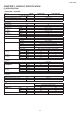
AY-ZP35PR CHAPTER 1. PRODUCT SPECIFICATION [1] SPECIFICATION 1. AY-ZP35PR – AE-Z35PR MODEL ITEMS Rated cooling capacity (Min. – Max.) Rated heating capacity (Min. –Max.) Moisture removal (at cooling) Electrical data Phase Rated frequency Rated voltage Rated current 䃩 (Min - Max.) Rated input 䃩 (Min - Max.) Power factor 䃩 Maximum operating current Compressor Refrigerant system Cooling Heating Cooling Heating Cooling Heating INDOOR UNIT AY-ZP35PR kW kW Liters/h 2.5 (1.3 - 3.0) 3.2 (0.9 - 5.0) 0.
AY-ZP35PR 2. AY-ZP40PR – AE-Z40PR MODEL ITEMS Rated cooling capacity (Min. – Max.) Rated heating capacity (Min. –Max.) Moisture removal (at cooling) Electrical data Phase Rated frequency Rated voltage Rated current 䃩 (Min - Max.) Rated input 䃩 (Min - Max.) Power factor 䃩 Maximum operating current Compressor Refrigerant system Cooling Heating Cooling Heating Cooling Heating INDOOR UNIT AY-ZP40PR kW kW Liters/h 3.5 (1.3 - 4.0) 4.0 (0.9 - 6.0) 1.2 Single 50 220-240 4.8 ( 1.8 - 6.5 ) 4.8 ( 1.3 - 8.
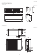
AY-ZP35PR [2] EXTERNAL DIMENSION 1. Indoor unit Length unit: mm 18.5 175 58 22.0 205 292 860 2. Outdoor unit Length unit: mm 135 72 299 324 540 12 37.5 58 14 265 81 136 540 780 165 167.
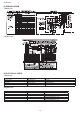
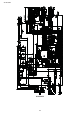
AY-ZP35PR [3] WIRING DIAGRM 1. Indoor unit 2 Outdoor Unit [4] ELECTRICAL PARTS 1. Indoor unit DESCRIPTION Indoor fan motor Indoor fan motor capacitor Transformer FUSE1 MODEL SFN-230-22-4F-1 A155BLS1S40D VRK4119-290mA - REMARKS AC Motor RTRNPA030JBZZ QFS-IA002JBZZ (250V, 2.5A) MODEL 5RS102XBE01 ARW84038H - REMARKS DC Motor DC Motor QFS-GA077JBZZ(250V, 2A) QFS-GA078JBZZ(250V, 3.
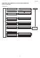
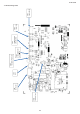
AY-ZP35PR CHAPTER 2. EXPLAMATION OF CIRCUIT AND OPERATION [1] BLOCK DIAGRAMS 1. Indoor unit 5VDC regulation 12V DC regulation AC power 2.5A Fuse Fan motor phase control circuit Indoor fan motor Rotation pulse input circuit Fan motor pulse detect AC clock circuit Remote controller signal reception circuit Wireless remote control operation Buzzer drive circuit Audible operation confirmation CPU reset circuit CPU Room temp. detect circuit Room temp.
AY-ZP35PR 2. Outdoor unit AC clock circuit Pulse amplitube modulation circuit IGBT Power supply circuit Power factor converter circuit Smoothing circuit Filter circuit 20A protection CPU oscillator circuit 3.
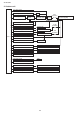
AY-ZP35PR [2] MICROCOMPUTER CONTROL SYSTEM 1. Indoor unit 1.1.
AY-ZP35PR AY-ZP40PR 2-4
CN10 terminal fuse CN1 fan motor CN6 PCI CN3 stepping motor of ver cal CN5 feedback of fan motor CN4 stepping motor of horizontal CN2 thermistor CN7 display board AY-ZP35PR 1.2.
AY-ZP35PR 2. Outdoor unit 2.1.
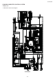
㼀㼛㻌㻾㼑㼍㼏㼠㼛㼞㻔㻳㼞㼍㼥㻕 㻲㼞㼛㼙㻌㻯㼛㼙㼜㼞㼑㼟㼟㼛㼞㻌㻔㻯㻕㻔㼃㻕㻔㻻㼞㼍㼚㼓㼑㻕 㻲㼞㼛㼙㻌㻯㼛㼙㼜㼞㼑㼟㼟㼛㼞 (R)(V)(White) 㻲㼞㼛㼙㻌㻯㼛㼙㼜㼞㼑㼟㼟㼛㼞㻌㻔㻿㻕㻔㼁㻕㻌㻔㻾㼑㼐㻕 㻲㼞㼛㼙㻌㻲㼍㼚㻌㻹㼛㼠㼛㼞 㻲㼞㼛㼙㻌㼀㼔㼑㼞㼙㼕㼟㼠㼛㼞 2-7 㼀㼛㻌㼀㼑㼞㼙㼕㼚㼍㼘㻌㻮㼛㼍㼞㼐㻔㻺㻕 㻌㻔㻮㼘㼡㼑㻕 㼀㼛㻌㻯㼛㼚㼠㼞㼛㼘㻌㻮㼛㼤 㻔㻳㼞㼑㼑㼚㻛㼅㼑㼘㼘㼛㼣㻕 㼀㼛㻌㼀㼑㼞㼙㼕㼚㼍㼘㻌㻮㼛㼍㼞㼐㻔㻞㻕 㻌㻔㻾㼑㼐㻕 㼀㼛㻌㼀㼑㼞㼙㼕㼚㼍㼘㻌㻮㼛㼍㼞㼐㻔㻝㻕 㻌㻔㻮㼞㼛㼣㼚㻕 㻲㼞㼛㼙㻌㻠㼃㼍㼥㻌㼂㼍㼘㼢㼑 㻲㼞㼛㼙㻌㻱㼤㼜㼍㼚㼟㼕㼛㼚㻌㼂㼍㼘㼢㼑 AY-ZP35PR 2.1.
AY-ZP35PR [3] FUNCTION 1.6. Indoor unit overheat prevention control 1. Function 1.1. Startup control The main relay remains off during the first 45 seconds (first safety time) immediately after the power cord is plugged into an AC outlet inorder to disable outdoor unit operation and protect outdoor unit electric components. 1.2. Restart control Once the compressor stops operating, it will not restart for 180 seconds to protect the compressor.
AY-ZP35PR 1.10. Peak control 1.15. Power ON start If thecurrent flowingin the air/air heat pump exceeds the peak control current (see the table below), the operation frequency is decreased until the current value drops below the peak control current regardless of the frequency control demand issued from the indoor unit based on the room temperature.
AY-ZP35PR For vertical adjustment louvre: 1.20. Difference of operation in Auto and Manual modes In the Auto mode, the temperature setting is automatically determined based on the outside air temperature. In addition, the air/ air heat pump operation differs from the operation in the Manual mode as explained below. AIR FLOW DIRECTION 1.21. Difference relating to set temperature Temperature setting method 1)Press the SWING button( ) on the remote control once.
AY-ZP35PR 1.24. Self Clean operation O 0.6 C Heating or Fan operation and Cluster operation are performed simultaneously. Hot keep zone Set temperature The judgment of whether Heating or Fan operation is used is based on the outside air temperature at 3 minutes after the start of internal cleaning. The operation stops after 40 minutes. 1.28. Winter cool Cooling operation is available during the winter season by the built in winter cool function. Lower limit of outdoor temperature range is -10°C DB.
AY-ZP35PR 2. Explanation of cluster circuit !& ?'_ &; _+* &+&;# & ?'_ &; * + =!*?! #;& ?*;?_'# &` !; _! _ !& ; < @ !& #;* \ = ?;&# &` @ !& ' =&; >#+ *+` ; _+* fan) in the air/air heat pump unit. When microcomputer output turns "H", the Q11 output changes to "Lo", turning ON the cluster unit for the generation of cluster ions (positive and negative ions). Cluster unit 12V Q11 Microcomputer output R39 1 1 3 3 3. Outline of PAM circuit 3.1.
AY-ZP35PR The power source frequency is also determined at the same time. The IGBT turns ON after the time length determined by the zero-cross point to supply a current to the IGBT via the reactor. This brings the current waveform closer to the voltage waveform in phase.
AY-ZP35PR 3.3.1 Details of troubleshooting procedure for PAM 1) PAM shutdown due to error !&+ !& ' #& `& &? * + ?*;?_* &+` # *+#' &?&&`*+ !& $&?*&` ' #& !& <*?; ? <$_ &; DC voltage of 350 V or higher (detection circuit input voltage of about 9.
AY-ZP35PR The power supply for the subsequent stages is charged while the lower-phase IGBT is ON in ordinary compressor drive control. Initial charge period Charging current group P(Vcc) Bootstrap capacitor (HU,HV,HW) HVIC VDB U,V,W, High-voltage-withstanding, high-speed recovery diode N-side IGBT (LU,LV,LW) VD LVIC VCIN(n) N(GND Bootstrap circuit 4.1.
AY-ZP35PR P Shunt resistance Overcurrent R49 N 5V IC1 34 IPM overcurrent detection circuit CiN 26 FO 0V 24 51 56 5. 120° Energizing control (digital position detection control) This control system detects the digital position detection signal and adjusts the rate of acceleration/deceleration accordingly.
AY-ZP35PR 6.
AY-ZP35PR CHAPTER 3.
AY-ZP35PR Function Operation Description 25 Compressor startup error 26 Compressor rotation error (at 120° energizing) 27 Outdoor unit DC fan error 28 PAM overvoltage error Reset condition When compressor is in Replacement of defec- Yes ۼ1 non-operation tive parts such as IPM Yes Yes Yes ۼ2 Yes Yes Yes ۼ2 Yes Yes 3 minutes after com- Operation OFF or ON pressor startup Yes ۼ2 Yes Yes When in operation Operation OFF or ON Yes ۼ2 Yes Yes At compressor startup Operation O
AY-ZP35PR Function Operation Description 29 PAM clock error Detection period Reset condition Self-diagnosis result display Indoor Indoor unit Outdoor unit error unit display When power source frequency At compressor startup, Compressor continues None cannot be determined (at start- when in operation operation without stopup), or when power source clock ping. cannot be detected for 1 continuous second (at startup).
AY-ZP35PR 2.
AY-ZP35PR [3] THERMISTOR TEMPERATURE CHARACTERISTICS 1. Indoor unit thermistor temperature characteristics TH1 TH2 K 100 CN2 4 3 2 1 CN2 80 Resistance (K ) - - + + 60 Tester 40 Tester Thermistor Symbol Room temperature TH1 (CN2) Heat exchanger TH2 (CN2) Heat exchanger thermistor TH2 (orange) Resistance at 25 : 4.431k Room temperature thermistor TH1 (yellow) Resistanceat25 : 10 k 20 Before measuring resistance, disconnect connectors as shown Yellow above.
AY-ZP35PR [5] GENERAL TROUBLESHOOTING CHART 1. Indoor unit does not turn on Main cause Cracked PWB. (Cracked pattern) Open-circuit in FU1 (250 V, 2.5A). Inspection method Check visually. Normal value/condition There should be no cracking in PWB or pattern. There should be no open-circuit. Check melting of FU1. Remedy Replace PWB. Replace PWB. 2.
AY-ZP35PR Main cause TV/radio is placed too close to outdoor unit. Inspection method Check distance between TV/radio and outdoor unit. Normal value/condition If TV/radio is placed too close, it may become affected by noise. Remedy Move TV/radio away from outdoor unit. Normal value/condition Terminal board 1-N: 230 VAC, 50 Hz Terminal board 2: serial signal Remedy Correct wiring. 7. Compressor does not start Main cause Erroneous inter-unit connection.
AY-ZP35PR Connect power cord to AC outlet. Check 220-240 VAC between (1) and (N) on outdoor unit PWB. Replace outdoor unit PWB. YES Is LED1 on outdoor unit flashing? NO Does LED1 remain lit? No (unlit) NO Check 320 VDC between pins IPM (20) and (24)? NO Disconnect (CN3) lead wires of FAN motor. LED1 is flashing. YES YES YES YES Replace FAN motor. Using remote control, operate air conditioner so that compressor starts. Serial signal error. Check inter-unit wiring.
AY-ZP35PR 2. Procedure for determinin g defective expansio n valve Measure resistance in expansion valve coil. Normal resistance between red terminal of expansion valve lead wire and white or orange terminal,gray terminal of expansion valve lead wire and yellow or blue terminal : about 46 (at 20 ) LED (red) NO YES Checker Insert checker shown at left into connector (CN12) on control PWB, and operate air conditioner. 5.6K 5.6K 5.6K 5.6K Replace control PWB.
AY-ZP35PR 5. IPM check method Turn off the power, let the large capacity electrolytic capacitor (C10) discharge completely, and dismount the IPM. Then, using a tester, check leak current between C and E. When using a digital tester, the (+) and (-) tester lead wires in the table must be reversed. Needle-type tester (-) (+) P N U V W Needle-type tester (-) (+) U N V W Normal resistance value ∞ (several MΩ) Normal resistance value ∞ (several MΩ) Values in ( ) are for digital tester. 5.1.
AY-ZP35PR 6. DC Over Current Error ( 6-0 error) *1 6-0 error memory is recorded. Check the connection of compressor lead wire on PWB. TU : RED TV : WHITE TW : ORANGE Refer to "IPM CHECK METHOD". Check the connection of compressor terminal marking. Refer to " DISASSEMBLING PROCEDURE OUTDOOR UNIT". Check to make sure thermistors are installed in correct portions. Refer to "THERMISTOR TEMPERATURE CHARACTERISTICS".
AY-ZP35PR No Item Check method Normal value/condition Remed y 2 Inverter DC power supply voltage check Measure DC voltage between IPM pins (31) and (35). 320 VDC Replace control PWB. Replace diode bridge. Correct soldered section of Fasten tabs (T1, T2, T5 - T3) on control PWB and IMP (S, C, R). (Repair solder cracks.) Replace control PWB. 3 IPM circuit check 4 Compressor check Each voltage should be normal. All 3 lamps (load) should light with same intensity. Resistance value at 20° C --- 0.
AY-ZP35PR 3. Caution in checking printed circuit boards (PWB) 3.1. Non-insulated control circuit The GND terminals of the low-voltage circuits (control circuits for microcomputer and thermistors and drive circuits for expansion valve and relays) on the control printed circuit board (PWB) are connected to the compressor drive power supply (320-VDC negative terminal). Therefore, exercise utmost caution to prevent electric shock.
AY-ZP35PR [8] TROUBLESHOOTING GUIDE 1. Self-Diagnosis Function 1. Indoor unit To display the self-diagnosis, hold down the AUX button for over 5 seconds on the indoor unit when the indoor unit is not operating. The operation lamp (green), timer lamp (orange) and Plasmcluster lamp (blue) flash to indicate the information of mulfunction. If the power cord is unplugged or the circuit breaker is turned off, the self-diagnosis memory is lost.
AY-ZP35PR [9] CHART :1-second ON / 1-second OFF Problem symptom Outdoor unit indication (LED1) Normal con- Normal dition blinking Indoor and outdoor units do not operate. 1-time Indoor unit Lamp Timer (Orange) Malfunction No.
AY-ZP35PR Problem symptom Indoor unit operates. Outdoor unit does not operate temporarily. Indoor and outdoor units do not operate. Outdoor unit indication (LED1) 3-time Indoor unit Lamp Timer (Orange) Malfunction No.
AY-ZP35PR Problem symptom Indoor and outdoor units do not operate. Outdoor unit indication (LED1) 7-time Indoor unit Lamp Timer (Orange) Malfunction No.
AY-ZP35PR Problem symptom Indoor and outdoor units do not operate. Outdoor unit indication (LED1) 9-time Indoor and outdoor units do not operate. Indoor and outdoor units do not operate. Lamp Timer (Orange) Malfunction No. Main Sub 9 0 Operation (Green) Content of diagnosis Main Cycle temperature Plasmacluster (Blue) Timer (Orange) Indoor and outdoor units do not operate. Indoor and outdoor units do not operate.
AY-ZP35PR Problem symptom Indoor and outdoor units do not operate. Outdoor unit indication (LED1) 11-time Indoor unit Lamp Timer (Orange) Malfunction No. Main Sub 11 0 Operation (Green) Plasmacluster (Blue) Timer (Orange) Content of diagnosis Main Check point Sub Outdoor unit Outdoor unit DC (1) Check connector (1) Correct the instalDC fan fan rotation error CN3 of the outdoor lation. unit DC fan motor for secure installation.
AY-ZP35PR Problem symptom Indoor and outdoor units do not operate. Outdoor unit indication (LED1) 13-time Indoor unit Lamp Timer (Orange) Malfunction No. Main Sub 13 0 Operation (Green) Content of diagnosis Main DC compressor Plasmacluster (Blue) Timer (Orange) 1 Operation (Green) Plasmacluster (Blue) Timer (Orange) 2 Plasmacluster (Blue) Indoor and outdoor units do not operate.
AY-ZP35PR Problem symptom Indoor unit operates. Outdoor unit does not operate. Outdoor unit indication (LED1) Lighting or OFF Indoor unit Lamp Timer (Orange) Malfunction No. Main Sub 17 0 Operation (Green) Content of diagnosis Main Wiring between units Check point Sub Serial open-cir- (1) Check the wires cuit between units. Plasmacluster (Blue) (2) (3) (4) (5) (6) Indoor unit Lighting operates. or OFF Outdoor unit does not operate. Indoor and Lighting outdoor units or OFF do not operate.
AY-ZP35PR Problem Outdoor Indoor unit symptom unit indication Lamp (LED1) Indoor and Normal { { { { { Timer(Orange) outdoor blinking { { { Operation(Green) units operor OFF { Plasmacluster ate. (Blue) Malfunction No.
AY-ZP35PR EHP6.0AA/I CHAPTER 4. REFRIGERATION CYCLE 5GTXKEG /CPWCN [1] SCHEMATIC DIAGRAM Indoor unit Evaporator 3 Flare coupling Flare coupling 3-way 2-way valve valve Heating Cooling Silencer Strainer s Outdoor unit Accumulator 4 1 Antifreeze pipe Silencer Expansion valve Compressor Coil C Reverse valve Condenser 2 [2] STANDARD CONDITION Indoor side Dry-bulb Temp. (° C) Relative Humidity (%) 27 47 – 20 Cooling Heating * Outdoor side Dry-bulb Temp.
AY-ZP35PR 1. AY-ZP35PR 1.1. At Cooling 1.2. At Heating 㪎㪇㪇㩷 㪏㪌㪇㩷 㪏㪇㪇㩷 㪠㫅㫇㫌㫋㩷㩿䌗㪀 㪠㫅㫇㫌㫋㩷㩿㪮㪀 㪍㪌㪇㩷 㪍㪇㪇㩷 㪎㪌㪇㩷 㪎㪇㪇㩷 㪌㪌㪇㩷 㪍㪌㪇㩷 㪌㪇㪇㩷 㪍㪇㪇㩷 㪉㪇 㪉㪌 㪊㪇 㪊㪌 㪋㪇 㪋㪌 㪄㪈㪇 㪄㪌 㪇 㪌 㪈㪇 㪈㪌 㪦㫌㫋㫊㫀㪻㪼㩷㪸㫀㫉㩷㫋㪼㫄㫇㪅㩷㩿㷄㪀 㪊㪅㪌㩷 㪋㪅㪇㩷 㪊㪅㪇㩷 㪊㪅㪌㩷 㪟㪼㪸㫋㫀㫅㪾㩷㪺㪸㫇㪸㪺㫀㫋㫐㩷㩿㫂㪮㪀 㪚㫆㫆㫃㫀㫅㪾㩷㪺㪸㫇㪸㪺㫀㫋㫐㩷㩿㫂㪮㪀 㪦㫌㫋㫊㫀㪻㪼㩷㪸㫀㫉㩷㫋㪼㫄㫇㪅㩷䋨㷄䋩 㪉㪅㪌㩷 㪉㪅㪇㩷 㪊㪅㪇㩷 㪉㪅㪌㩷 㪉㪅㪇㩷 㪈㪅㪌㩷 㪉㪇 㪉㪌 㪊㪇 㪊㪌 㪋㪇 㪦㫌㫋㫊㫀㪻㪼㩷㪸㫀㫉㩷㫋㪼㫄㫇㪅㩷䋨㷄䋩 㪄㪈㪇 㪋㪌 㪄㪌 㪇 㪌 㪈㪇 㪦㫌㫋㫊㫀㪻㪼㩷㪸㫀㫉㩷㫋㪼㫄㫇㪅㩷㩿㷄㪀 㪈㪌 2. AY-ZP40PR 2.2. At Heating 㪈㪈㪇㪇㩷 㪈㪉㪇㪇㩷 㪈㪇㪇㪇㩷 㪈㪈㪇㪇㩷 㪠㫅㫇㫌㫋㩷㩿䌗㪀 㪠㫅㫇㫌㫋㩷㩿㪮㪀 2.1.
AY-ZP35PR EHP6.0AA/I 5GTXKEG /CPWCN CHAPTER 5. DISASSEMBLING PROCEDURE If, in carrying out repairs and modifications, the work requires the use of arc- and flame-producing apparatus, such as welding, brazing and soldering equipment, this work shall only be started after the rooms have been thoroughly ventilated. While the work is being carried out, the mechanical ventilation, if any, shall be kept in constant operation and all windows and doors kept open.
AY-ZP35PR Pull the front panel toward in the direction shown the picture. 11) Remove the 5 connectors and remove the control box. 1 2 12) Remove the center shaft of the horizontal louver from louver holder with lifting the louver holder, and remove the horizontal louver from cabinet while warping. 8) Remove the thermistor cover and the thermistor wire. Remove a screw fixing the earth wire. 9) Unhook the A side of the control box cover from the control box, then unhook the B side and pull it away.
AY-ZP35PR When assembling them, insert the motor shaft in the boss of the cross flow fan to the ring position. Screw Catch Ring Screw b) Remove the tube cover. Insert the (–) screwdriver to A hole and then lean it to the right as lifting B part. 16) Take off the catch of guide R from cabinet and remove the guide. c) Remove the evaporator from the cabinet. catch part Take off the catch of the tube cover from the plate and move the evaporator upward.
AY-ZP35PR [2] HOW TO REMOVE PLASMACLUSTER UNIT(For the models with PLASMACLUSTER) 1) Take the tape off and cut the fixing band 2) Insert the thin board to center of gap and remove the hook of holder. Please be careful not to damage the lead wire. Lead the lead wire through the left side of HOOK B HOOK HOOKBB HOOK HOOK 3) When assemble the plasmacluster unit, insert part A to holder part indicated by big arrow.
AY-ZP35PR [3] DISASSEMBLY OF OUTDOOR UNIT 4) The screw on the right-hand side of front panel is removed 1) The fixed screw of control box cover is removed and control box cover is removed. 5) The screw on the right-hand side of front panel is removed 2) The 2 screws on the right-hand side of top plate ass’y is removed. 6) The 4 screws of the front of a front panel is removed. Then remove the front panel. 3) The 2 screws on the left-hand side of top plate ass’y is removed. Then remove top plate ass’y.
AY-ZP35PR 12) Remove the 2 screws fixed the bulkhead plate. 8) Unscrew the 3 screws on the back side of the side cover R, and remove the side cover R. 9) Unscrew the 3 screws on the side cover L, and remove the side cover L. 13) Remove the compressor covers 1, 2, 3,4 and 5. 5 10) Remove the connectors and reactor in the control box. 14) Remove the nut, and remove the terminal cover. 11) Remove the 2 screws fixed the control box.
AY-ZP35PR 15) Remove the lead wire, the thermistor, and the cover gasket. 19) Unscrew the 2 screws and remove the motor angle. 20) Thermistor position. Red 16) Remove the compressor cover. Black Yellow 17) Remove the 5 thermistors. Orange 18) Remove the outdoor fan.
AY-ZP35PR CONTROL BOX 1.Control unit box's Approach to decomposition. 1) Cut the band 4) Take off box cover. BAND BOX COVER 2) Take off lead wires from terminal assembly. (Blue wire,Brown wire,Red wire,Green/Yellow wire) 5) Take off heat sink holder. HEAT SINK HOLDER 6) Take off screws (8 PCS) 3) Take off screw (earth). Take off earth lead wire (green/yellow) from terminal holder.
AY-ZP35PR PartsGuide PARTS GUIDE AIR/AIR HEAT PUMP MODEL INDOOR UNIT AY-ZP35PR AY-ZP40PR OUTDOOR UNIT AE-Z35PR AE-Z40PR CONTENTS [1] INDOOR UNIT PARTS [4] OUTDOOR UNIT PARTS [2] ACCESSORY PARTS [5] OUTDOOR PACKING PARTS [3] INDOOR PACKING PARTS Parts marked with " " are important for maintaining the safety of the set. Be sure to replace these parts with specified ones for maintaining the safety and performance of the set.
AY-ZP35PR [1] INDOOR UNIT PARTS 2-31 2-27 2-23 3-4 2-5 2-3 2-14 2-3-1 2-12 2-3-2 2-9 2-8 2-15-2 2-7 2-4 2-46 2-41 2-28 1-9 2-19 1-10 2-1 2-16 2-47 2-5-2 2-18 1-3 1-11 2-24 2-5-1 2-57 2-2 2-17 2-58 2-33 2-29 2-21 2-26 2-34 2-11-2 2-22-1 2-10-2 2-22-2 2-21-1 2-43-2 2
AY-ZP35PR NO.
AY-ZP35PR NO.
AY-ZP35PR NO. PARTS CODE PRICE RANK NEW MARK PART RANK DESCRIPTION [2] ACCESSORY PARTS 4-1 PGUMSA420JBEZ 4-2 CRMC-A873JBEZ CABLE SHEET 4-3 LX-BZA357JBEZ 4-4 LX-NZA207JBEZ SPECIAL NUT 4-5 XTTS740P20000 TAPPING SCREW 4-6 XTTS745P30000 TAPPING SCREW 4-7 LHLD-A849JBFA CORD HOLDER 4-9 TINS-B432JBRZ N INSTALLATION MANUAL 4-11 TINSEA772JBRZ N OPERATION MANUAL 4-12 UBATUA027JBE0 N REMOTE CONTROL SPECIAL SCREW BATTERY PACK [3] INDOOR PACKING PARTS 90-1 90-2 90-3 90-4 NO.
AY-ZP35PR [4] OUTDOOR UNIT PARTS 2-2 4-1 2-34 4-2 2-17 2-48-3 2-60 2-48-1 2-46-2 2-57 2-48-2 2-46-1 2-26 2-7 2-1 2-7-1 2-7-4 2-7-2 2-60-1 2-46-3 2-33 1-1 2-25 2-7-5 2-39-3 2-31 2-3 2-37 2-7-3 2-20 1-2-6 2-5 1-2-7 1-2 3-12 1-9 1-10 2-10 2-39-7 2-19 2-56 2-9 1-2-8 2-8 2-7-6 2-18 2-38 2-21 2-11 2-13 1-11 2-14 2-39-6 2-12 1-6 2-39-2 2-14-1 2-24 3-24 2-27-1 1-12 1-4 2-58 3-6 3-9 3-8 2-23 3-20 2-27 3-6-1 1-7 2-28 2-21 3-6-4 3-6-3 2-40 2-42 3-15 3-6-2 3-18
AY-ZP35PR NO.
AY-ZP35PR NO.
AY-ZP35PR NO.