AF-R100CX AF-R120CX SERVICE MANUAL S3203AFR12CX/ AIR CONDITIONER MODELS AF-R100CX AF-R120CX In the interest of user-safety the air conditioner should be restored to its original condition and only parts identical to those specified should be used. TABLE OF CONTENTS Page SPECIFICATIONS ................................................................................................................................................. 2 WIRING DIAGRAM .........................................................
AF-R100CX AF-R120CX SPECIFICATIONS Models Cooling capacity Moisture removal BTU/h Pints/h AF-R100CX 10000 2.7 AF-R120CX 12000 3.3 Hz Volts Amps Watts % BTU/Wh Single 60 115 9.0 1000 97 10.0 11.5 1200 91 10.0 COMPRESSOR Type Model, Remarks (Hermetically sealed rotary type) 44R251AC-AJS, 840 W 44B124HX1EF, 1000W REFRIGERANT SYSTEM Evaporator Condenser Control O.D. x I.D. x Length x Q'ty(mm) Refrigerant volume R-22(OZ) Slit fin, Grooved tube, Ø 9.
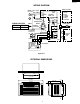
AF-R100CX AF-R120CX WIRING DIAGRAM POWER SUPPLY CORD 115V 60Hz NON RIBBED GR IN MRY OUT FU1 CONTROL BOAD UNIT BK OVERLOAD PROTECTOR BK COMPRESSORC MOTOR RIBBED RUNNING CAPACITOR RUNNING S R AF-R100CX AF-R120CX CAPACITOR WH RE 250V 60µF 370V 50µF FAN MOTOR CAPACITOR 250V 6µF x 2 BK BL WIRE COLOR BK : BLACK BL : BLUE RE : RED WH : WHITE GR : GREEN GY : GRAY OR : ORANGE 3A 125V NR C1 TR YELLOW CNR1 CNR2 GY 8 7 1 3 5 BK BL 1 2 3 6 5 4 CONNECTOR BCN1 BL BK GY RE OR WH H M L FAN MOTOR THERMAL PROTECTO
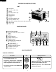
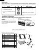
AF-R100CX AF-R120CX OPERATION INSTRUCTIONS UNIT 1 2 3 4 5 6 7 8 9 10 11 12 Front panel Air inlet (Indoor side) Louvers Air outlet (Indoor side) Exhaust lever Control panel 5 6 4 7 8 3 9 10 Cabinet 2 Air outlet (Outdoor side) 1 Air inlet (Outdoor side) Filter (Pull the filter handle to the right to remove.
AF-R100CX AF-R120CX TO CHANGE TEMPERATURE SETTING Procedure During cooling operation Pad Display / Indicator TEMP F Touch the TEMPERATURE setting pad to adjust the temperature setting. • It can be set within the range of 64°F to 86°F. hr ---Lower temp. ---Raise temp. • Display will change as you touch the pad. The latest temperature setting will be memorized and will appear on the display the next time the unit is turned on.
AF-R100CX AF-R120CX ENERGY SAVER During normal operation, the thermostat automatically controls cooling and the fan runs continuously. When the ENERGY SAVER is selected, the thermostat automatically controls cooling and the fan automatically stops when the compressor is not operating. (Fan will stop 30 seconds after the compressor stops.) Procedure Pad Display / Indicator During cooling operation 1. Touch ENERGY SAVER pad. 2. To cancel, touch ENERGY SAVER pad again.
AF-R100CX AF-R120CX SUGGESTED TOOLS CAUTION Do not remove any material (ex. styrofoam, etc.) from inside the unit. 1. Screw driver (medium size Phillips) 2. Tape measure or ruler 3. Knife or scissors INSTALLATION These models can also be installed through the wall with the optional through the wall mounting kit, model AZ80WK. To order this kit either contact your dealer or call 1-800-BE-SHARP.
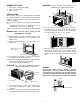
AF-R100CX AF-R120CX 6. Insert the closure assemblies on both sides into the rails of the jamb. Jamb (Left) Closure assembly (Left) Closure assembly (Left) Sill 1/2 inch (13mm) 9-1 Replace the front panel. Slip the exhaust lever through the opening between the horizontal louver and the front panel then, hook the cabinet top. CAUTION:Take care not to damage the exhaust lever with the front panel. 9-2. Screw the front cabinet on at the bottom corners with 2 screws removed in step 2. Stool 7-1.
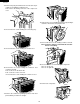
AF-R100CX AF-R120CX 8. Unscrew the one screw holding earth wire . 3. Unscrew the four screws holding the cabinet. Two screws are on top side. Two screws are on each side. 9. Cut the fixing band holding the wires. 4. Slide the chassis away from the cabinet by pulling on each corner of the base pan. 10.Remove the control unit. 5. Unscrew the four screws holding the control unit. Two screws are on front side. Two screws are on right side. 11.Unscrew the four screws holding control box cover.
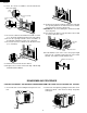
AF-R100CX AF-R120CX 13.Remove the putty and unfasten the one nut at the top of compressor holding the terminal cover. Then remove the wiring connector of the compressor cord. 18.Unfasten the one nut holding propeller fan by rotating it clockwise. And remove the propeller fan. 14.Unscrew the five screws holding the connecting stay. 19.Unscrew the three screws holding condenser shroud. Note: Seal three female screws with siliconsealer before re-installing. 15.
AF-R100CX AF-R120CX 22.Unscrew the four screws holding the bulkhead. Three screws are on the each side. One screw is on the bottom side. Note: Seal one female screws with siliconsealer before re-installing. 27.Unscrew the three screws holding the printed wiring board. 23.Unscrew the two screws holding the orifice 28.Detach terminals by using long-nose pliers. 24.Unfasten the one screw holding the centrifugal fan by rotating it counterclockwise. 29.Unscrew the five screws.
AF-R100CX AF-R120CX HOW TO REPAIR REFRIGERATION Before sealed system work can be preformed a refrigerant recovery EPA and LOCALLY approved certification is required, additionally, EPA and LOCALLY approved refrigerant recovery equipment is required. SEALED SYSTEM REPAIR Sealed system repairs should be properly diagnosed before entering into a repair of the system.
AF-R100CX AF-R120CX HEATING THE TUBING Direct the torch flame so that the larger tube receives most of the heat. Silver solder flows at 1200˚F and silfos flows at 1300˚F. Heat all around the tubing. The flame is composed of two cones, a smaller inner cone (pale blue) in color and a much larger outer cone. The hottest part of the flame is at the tip of the inner cone. The flame should be directed at the joint with the tip of the cone just touching the surface of the tubing. Figure 3 and 4.
AF-R100CX AF-R120CX A very faint green indicates a small leak. The flame will be unmistakably changed to green or purple when large leaks are encountered. To simplify leak detection pressurize the system to approximately 75 lbs. Some leaks can be located by a visual inspection of the system components and solder joints and if oil is found at any given location it generally is a sign that a leak exists at that point due to the fact that flame does carry oil with it travels through the system.
AF-R100CX AF-R120CX MICROCOMPUTER CONTROL SYSTEM 1. Temperature control characteristic 1-1 COOL operation In the “COOL” mode, the thermostat circuit is controlled by two thermostat lines (C1, C2). 3. Fan speed Fan speeds are given by the fan motor, “H”, “M” and “L”, which are available in the following operation mode. Room temperature (°F) Table Y-1 86 C1 84 C2 Fan motor H M L M 4. 12-hours timer 64 62 64 Preset temperature (°F) ("THERMO" switch) 86 Figure Y-1 2.
AF-R100CX AF-R120CX 6. Safety start When you turn the air conditioner OFF and restart again soon, wait at least 3 minutes before the cooling operation starts. 7. Test mode Keep pushing both buttons “POWER ON/OFF” and “ " ” and supply the power, the system will go to the test mode. In this mode, the output operation is switched by pushing buttons. Normal outputs are shown in Table Y-2. Table Y-2 No.
BK BL BK BK M CONNECTOR WHITE ORANGE RED GRAY R BL FAN MOTOR A H M L 5 3 1 6 7 C S RY1 CNR1 RY2 CNR2 RY3 CNR3 YELLOW C13 16V 10µF R22 10k(F) NO INSERT PART 25˚C TH1(15k) ROOM Temp CNR1 - CNR3 BCN1 RUNNING CAPACITOR COMPRESSOR MOTOR OVERLOARD PROTECTOR 3A 125V CN1 IF NOT SPECIFIED 1SS133T-72 (DIODE) : INDICATED POSITION IS FUNCTION TEST POINT RY3 RY2 RY1 MRY C13 + R9 10K D8 C14 16V 10µ + D7 D6 D5 R1 22K D3 SW1: ENERGY SAVER SW2: TIMER SW3: SELECTOR SW4: POWER S
AF-R100CX AF-R120CX DPWBFA193JBKZ 7 D8 RY1 JP4 D7 GND D6 RY3 CNR3 8 R 94V0 R15 JP23 D13 (GRAY) CNR2 CNR1 1 BCN3 (FAN MOTOR) (RED) Printed Wiring Board 18 OUT MRY C1 C19 C7 JP3 C16 R7 AE2A V0 AE2B V0 VB C6 R6 IN C11 FU1 JP2 8888 8 C20 C22 1 RY2 1 CN3 12V POWER CORD C21 NR R5 C12 125V 3A OUT IC3 8 E 5V 7 COM D1 C5 JP1 D3 D2 D17 C4 R21 R20 C15 CN2 RA1 OUT E E D5 R3 IC1 E B B Q4 JP9 Q1 28 JP5 B C B JP8 15 JP10 R8 Q3 TEST COMP JP7 OSC JP6
AF-R100CX AF-R120CX TROUBLESHOOTING GUIDE No cooling (Operation not at all.) Measure the power supply voltage at receptacle. under 100V 120V(over 100V) The house fuse or circuit breaker open ? not open. open Is it proper current capacity of the house fuse or the circuit breaker ? proper Ask the power supply company for check. not proper Change the house fuse and the circuit breaker turn on.
AF-R100CX AF-R120CX No cooling (Fan operate but the compressor doesn't operate.) Measure the power supply voltage at receptacle. under 100V Ask the power supply 120V(over 100V) company for check. insufficient Is it sufficient current capacity of power equipment ? Ask the power supply Is it small wiring for power company for check. supply equipment ? sufficient Measure the current in compressor circuit. current Check the overload relay. no current imperfect contact Change the overload relay.
AF-R100CX AF-R120CX No cooling (The compressor operate but the fan motor doesn't operate) crack at the solder part Check BNC1 on PWB ass'y Repair with over solder. disconnecting the connector Connect the connector properly. OK Check the fan motor capacitor. NG OK Measure the resistance of compressor coil. Change the fan motor capacitor NG OK Is the fan locked ? Change the fan motor. locked Is the fan touched to another parts ? touch Change fan or another parts, or adjust.
AF-R100CX AF-R120CX Insufficient cooling(Both compressor and compressor operate) Check the temperature setting. OK too high Set the lower temperature. dirty Check the air filter. not dirty Clean the air filter. Is there high heat source or any object restricting heat radiation near the unit. there is Remove the high heat source or stop. there isn't Check doors and windows. close Check the outdoor and indoor heat exchanger. open Doors and windows must be kept closed.
AF-R100CX AF-R120CX Excessive vibration or Abnormal noise At fan only mode, Excessive vibration or Abnormal noise YES Check the air filter dirty NO not dirty Check rotating direction of centrifugal fan.(to clockwise) OK Clean the air filter. NG Check the fan motor connector. OK Measure the resistance of fan motor coil. OK Is the fan deformed or broken. OK Is loosened screw and nut fixing fan ? OK deform or broken Change the fan loosened Tighten up.
AF-R100CX AF-R120CX COOLING LOAD ESTIMATE FORM INSTRUCTIONS FOR USING COOLING LOAD ESTIMATE FORM FOR ROOM AIR CONDITIONERS (AHAM PUB. NO. RAC-1) A. This cooling load estimate form is suitable for estimating the cooling load for comfort air conditioning installations which do not require specific conditions of inside temperature and humidity. B. The form is based on an outside design temperature of 95˚F dry bulb and 75˚F wet bulb.
AF-R100CX AF-R120CX BTU/Hr (Quantity x Factor) FACTORS HEAT GAIN FROM QUANTITY DAY No Shades 1. WINDOWS: Heat gain from sun. Northeast Southeast South Southwest Southeast West Northwest North Inside Shades Outside Shades 20 25 20 20 30 45 35 0 (Area a Factor) Use only the largest load Use only only 60 25 80 40 75 30 75 35 110 45 sq ft 150 65 sq ft sq ft 120 50 sq ft 0 0 These factors are for single glass only. For glass block, multiply the above factors by 0.
AF-R100CX AF-R120CX RUNNING CONDITION Note: 1. Select mode of the Running Condition of a Room Air Conditioner. SELECTOR ................................................ HIGH COOL TEMPERATURE .................................................... 64°F 2. Data of Performance Curve is measured between 40RH% and 70RH%. If you measure the Room Air Conditioner above or below this rating, the data may miss the range of the performance curve. 3. Outlet air temp. is influenced by the method of measurement.
AF-R100CX AF-R120CX PACKING AND ACCESSORIES Closure ass'y 4 Top pad B Top pad F 3 Packing case 2 Bag Bottom pad ass'y 1 27
AF-R100CX AF-R120CX REPLACEMENT PARTS LIST REF. NO. PART NO.
AF-R100CX AF-R120CX REF. NO. PART NO.
AF-R100CX AF-R120CX REF. NO. PART NO.
H 1 2 3 4 31 6-1 5 1-6 1-62 1-53 1-51 1-48 6-1 1-22 1-47 1-49 1-17 1-20 1-45 1-59 1-56 1-56 6-6 1-1 1-19 1-21 1-41 1-42 1-11 6-7 1-14 1-4 6-1 1-52 6-12 1-40 1-23 6-12 1-2 1-34 6-6 6-6 6-6 1-43 5-2 6-1 1-43 5-1 6-12 6-6 6-6 1-15 6-5 1-18 6-6 5-7 1-33 2-4 6-5 5-4 6-12 1-3 6-5 1-25 1-28 5-3 4 1-12 1-16 1-55 1-10 6-5 1-63 6-5 6-1 6-6 6-12 1-14 6-10 6-1 1-60 1-24 3 6-2 5-6 6-6 6-1 1-39 1-42 1-41 1-46 1-8 2 1-27 1-7 6-1 F 1-54 1
AF-R100CX AF-R120CX 2 1 A 3 CYCLE PARTS 4 5 6 A 6-4 3-8 3-9 3-14 2-7 3-4 3-10 B B 1-44 6-10 3-5 3-2 C C 3-15 3-13 6-10 3-3 3-12 6-10 6-1 3-11 3-1 D D 2-6 6-3 3-6 6-8 3-7 1-61 6-1 6-4 1-9 2-5 6-1 3-9 3-14 AF-R100CX E 2-7 3-4 3-10 E 1-44 6-10 3-5 3-11 F F 3-2 3-13 3-15 3-12 6-10 3-1 3-3 6-10 G G 6-1 6-1 2-6 3-6 6-3 6-8 3-7 1-61 6-1 6-1 1-9 2-5 H H AF-R120CX 1 2 3 4 32 5 6 '02 SHARP CORP. (2S0.85E) Printed in U.S.A.