
Operation Manual


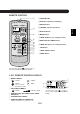


PART NAMES
1 Inlet (Air)
2 Open Panel
3 Air Filters
4 AUX. Button
5 RECEIVER Window
6 Power Supply Cord
7 Indicator Panel
8 Vertical Adjustment Louvres
9 Horizontal Adjustment Louvres
0 Outlet (Air)
q Remote Control
w
AUTO FAN SPEED Lamp
(green )
e FAN SPEED Lamp (green )
r TIMER Lamp (orange )
t OPERATION Lamp (red )
OUTDOOR UNIT
NOTE: Actual units might vary slightly from those shown above.
INDOOR UNIT
1
2
3
4
5
6
7
8
9
0
q
y Inlet(Air)
u Refrigerant Tube and
Interconnecting Cord
i Drainage Hose
o Outlet(Air)
E-4
w
e
r
t
y
u
i
o
y
u
i
o
AE-A09BE/AE-A12BE
AU-A09BE/AU-A12BE
AE-A07BE
AU-A07BE