
Operation Manual


ENGLISH
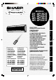
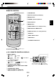
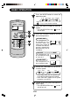
REMOTE CONTROL
1 TRANSMITTER
2 DISPLAY (Liquid Crystal Display)
3 ON/OFF Button
4 THERMO. (Thermostat) Button
5 DISPLAY Button
6 MODE Button
7 TIMER ON Button (for setting the timer)
8 ONE-HOUR OFF TIMER Button
9 TIMER OFF Button (for setting the timer)
0 FAN Button
q TIMER CANCEL Button
w SWING Button
e PLASMACLUSTER Button
(The heat mode symbol is provided
only on models AY-AP18CE/AY-AP24CE)
E-5
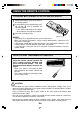
r MODE SYMBOLS
: AUTO : COOL
: HEAT : DRY : FAN ONLY
(only for
AY-AP18CE/AY-AP24CE)
t FAN SPEED SYMBOLS
: AUTO : Manual setting
y PLASMACLUSTER SYMBOL
u TEMPERATURE AND TIMER COUNT DOWN
INDICATOR
i TRANSMITTING SYMBOL
o TIMER ON/TIMER OFF INDICATOR
Indicates when timer on or timer off is set.
L.C.D. REMOTE CONTROL DISPLAY
(The heat mode symbol is provided only on
models AY-AP18CE/AY-AP24CE)
1
2
3
4
5
6
7
8
9
0
q
w
e
r
t
y
u
i
o
MODE
DISPLAY MODE
FAN1h
SWING
CANCEL
TEMP.
TEMP.
FAN TIMER