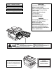
AL-1552 AL-1553 AL-1555 DIGITAL MULTIFUNCTIONAL SYSTEM OPERATION MANUAL
CLASS 1 LASER PRODUCT LASER KLASSE 1 LUKOAN 1 LASERLAITE KLASS 1 LASERAPPARAT VAROITUS! LAITTEEN KÄYTTÄMINEN MUULLA KUIN TÄSSÄ KÄYTTÖOHJEESSA MAINITULLA TAVALLA SAATTAA ALTISTAA KÄYTTÄJÄN TURVALLISUUSLUOKAN 1 YLITTÄVÄLLE NÄKYMÄTTÖMÄLLE LASERSÄTEILYLLE. VARNING OM APPARATEN ANVÄNDS PÅ ANNAT SÄTT ÄN I DENNA BRUKSANVISNING SPECIFICERATS, KAN ANVÄNDAREN UTSÄTTAS FÖR OSYNLIG LASERSTRÅLNING, SOM ÖVERSKRIDER GRÄNSEN FÖR LASERKLASS 1. Laserstrahl LASERSTRÅLING NÅR DEKSEL ÅPNES OG SIKKERHEDSLÅS BRYTES.
CAUTIONS Caution label on the unit The label ( ) in the fusing area of the unit indicates the following: : Caution, risk of danger : Caution, hot surface Cautions on using Follow the cautions below when using this unit. Warning: • The fusing area is hot. Exercise care in this area when removing misfed paper. • Do not look directly at the light source. Doing so may damage your eyes. • Do not switch the unit rapidly on and off. After turning the unit off, wait 10 to 15 seconds before turning it back on.
Cautions on handling Be careful in handling the unit as follows to maintain the performance of this unit. Do not drop the unit, subject it to shock or strike it against any object. Do not expose the drum cartridge to direct sunlight. • Doing so will damage the surface (green portion) of the drum cartridge, causing smudges on copies. Store spare supplies such as drum cartridges and TD cartridges in a dark place without removing from the package before use.
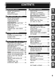
CONTENTS 1 INTRODUCTION USING THE MANUALS ................. 4 PART NAMES ................................ 5 OPERATION PANEL...................... 6 2 SETTING UP THE UNIT SETUP PROCEDURE ................... 7 CHECKING PACKED COMPONENTS AND ACCESSORIES ............................. 8 PREPARING THE UNIT FOR INSTALLATION .............................. 8 INSTALLING THE TD CARTRIDGE................................ 10 CONNECTING THE POWER CORD .......................................... 12 3 LOADING PAPER PAPER .
1 INTRODUCTION This chapter provides basic information for using the unit. USING THE MANUALS In addition to this printed manual an online manual is also provided. To get full use of all features and functions of this product, be sure to familiarise yourself with both manuals. This printed manual provides all installation and setup instructions as well as instructions in the use of all copier functions. The online manual contains the following information.
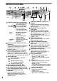
PART NAMES Original cover SPF (AL-1553) RSPF (AL-1555) (AL-1552) Original guide 1 Feeding roller cover Original exit area Original feeder tray Interface USB interface Parallel interface SPF (AL-1553) RSPF (AL-1555) scan area 1 2 5 6 7 3 8 9 10 11 4 Multi-bypass tray (AL-1553, AL-1555) TD cartridge Drum cartridge Paper tray 2 (AL-1555) Single bypass (AL-1552) 12 7 5 13 14 3 15 1 2 3 4 5 6 7 8 9 Original table Operation panel Front cover Paper tray Side cover Side cover open button Bypas
OPERATION PANEL AL-1555 1 2 3 4 141 A5 A4 86 70 A4 B5 A4 A5 Original to copy key and indicators Two-sided copies from one-sided originals. Turn on Long Edge or Turn on Short Edge can be selected. Two-sided copies from two-sided originals. (Can be selected only when the RSPF is used.) (AL-1555) Single-sided copies from two-sided originals. (Can be selected only when the RSPF is used.
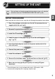
2 SETTING UP THE UNIT Follow the installation procedure below to use the unit properly. If the unit does not function properly during setup or use, or if a function cannot be used, see "TROUBLESHOOTING THE UNIT" (p.61). SETUP PROCEDURE 2 When using the unit for the first time, setup the unit following the procedure shown below. 1 Open the package, and make sure that all the accessories are supplied with the unit. (p.8) 2 Remove the protective materials. (p.9) 3 Install the TD cartridge. (p.
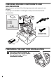
CHECKING PACKED COMPONENTS AND ACCESSORIES Open the carton and check if the following components and accessories are included. If anything is not included or is damaged, contact your authorised service representative. Operation manual AL-1552 AL-1553 AL-1555 Software CD-ROM Drum cartridge (installed in unit) TD cartridge PREPARING THE UNIT FOR INSTALLATION 1 8 Be sure to hold the handles on both sides of the unit to unpack the unit and carry it to the installation location.
2 Remove all pieces of tape shown in the illustration below. Then open the original cover/SPF/RSPF and remove protective materials. After that, take out the bag containing the power cord and TD cartridge. (AL-1555 only) (AL-1555) 2 AL-1552 AL-1553, AL-1555 AL-1553, AL-1555 AL-1552 3 Release the scan head locking switch. The scan head locking switch is under the original table. If the switch is locked ( ), the unit will not operate. Unlock the switch ( as shown below.
INSTALLING THE TD CARTRIDGE 1 Open the multi-bypass tray (AL-1553, AL-1555, p.17), and then open the side cover. 2 Push gently on both sides of the front cover to open the cover. 3 Remove the TD cartridge from the bag. Hold the cartridge on both sides and shake it horizontally four or five times. Hold the tab of the protective cover and pull the tab to your side to remove the cover. 4 or 5 times 4 10 Gently insert the TD cartridge until it locks in place while pushing the lock release button.
5 Close the front cover and then the side cover by pressing the round projections near the side cover open button. When closing the covers, be sure to close the front cover securely and then close the side cover. If the covers are closed in the wrong order, the covers may be damaged.
CONNECTING THE POWER CORD If you use the unit in a country other than the country where the unit was purchased, you will need to make sure that your local power supply is compatible with your model. If you plug the unit into an incompatible power supply, irreparable damage to the unit will result. 1 Ensure that the power switch of the unit is in the OFF position. Insert the attached power cord into the power cord socket at the rear of the unit.
About the scan head The scan head lamp remains on constantly when the unit is in the ready condition (when the start ( ) indicator is illuminated). The unit adjusts the scan head lamp periodically to maintain copying quality. At this time, the scan head moves automatically. This is normal and does not indicate unit trouble. Initial settings of operation panel When the unit power is on, the operation panel will revert to the initial settings when the time set with the "Auto clear time" setting (p.
3 LOADING PAPER Follow the steps below to load paper into the tray. PAPER For best results, use only paper recommended by SHARP.
LOADING THE PAPER TRAY 1 Raise the handle of the paper tray and pull the paper tray out until it stops. 2 Remove the pressure plate lock. Rotate the pressure plate lock in the direction of the arrow to remove it while pressing down the pressure plate of the paper tray. 3 3 Store the pressure plate lock which has been removed in step 2. To store the pressure plate lock, rotate the lock to fix it on the relevant location.
5 Fan the paper and insert it into the tray. Make sure the edges go under the corner hooks. Do not load paper above the maximum height line ( the line will cause a paper misfeed. 6 ). Exceeding Gently push the paper tray back into the unit. • After loading paper, to cancel the blinking without restarting copying, press the clear ( ) key. The in the display will go out and the start ( ) indicator will light up. • Be sure that paper is free of rips, dust, wrinkles, and curled or bent edges.
BYPASS FEED (including special paper) The multi-bypass tray (AL-1553, AL-1555) or the single bypass (AL-1552) can be used to feed standard paper, transparency film, labels, envelopes, and other special purpose paper. Paper measuring from A6 to A4 and in the weight range of 52g/m2 to 128g/m2 can be used in this tray. (For paper weighing from 104g/m2 to 128g/m2, A4 is the maximum size.) • The multi-bypass tray (AL-1553, AL-1555) can hold maximum of 50 sheets of paper.
The single bypass (AL-1552) • If you insert a sheet of paper into the single bypass when multiple copies have been set with the copy quantity setting (p.49), the copy quantity setting will change to "0" and only one copy will be made. • When copying onto transparency film, remove each copy promptly. Do not let copies stack up. 1 Select copy settings before you begin the copy job. 2 Set the paper guides to the paper width.
4 INSTALLING THE SOFTWARE This chapter explains how to install the software that allows the AL-1552, AL1553 and AL-1555 to be used as a printer and scanner, and the procedures for using the printer and scanner functions. The following term is used in this chapter. CD-ROM Means the supplied CD-ROM with the SHARP Personal MFP series software. SOFTWARE FOR THE SHARP PERSONAL MFP SERIES The supplied CD-ROM includes software for this unit.
HARDWARE AND SOFTWARE REQUIREMENTS Check the following hardware and software requirements in order to install the software. Computer type IBM PC/AT or compatible computer equipped with a USB1.1*1 or bi-directional parallel interface (IEEE 1284) Operating system*2 Windows 95, Windows 98, Windows Me, Windows NT Workstation 4.
Flow of installation Refer to the following table and then begin installation. Operating system Windows XP Windows 98 Interface Reference pages for how to install USB/ Parallel USB Installing onto Windows XP (USB/parallel interface) (p.22) Installing onto Windows 98/Me/2000 (USB interface) (p.26) Installing onto Windows 95/98/Me/NT4.0/2000 (Parallel interface) (p.29) Installing onto Windows 98/Me/2000 (USB interface) (p.26) Installing onto Windows 95/98/Me/NT4.0/2000 (Parallel interface) (p.
INSTALLING THE SOFTWARE The following term is used in this section. MFP Means the unit as a printer and scanner. • For this description, it is assumed that the mouse is configured for right hand operation. • To print or scan, the MFP must be in the online state. • The scanner feature only works when using a USB interface cable. • If any error message appears, solve the problem following the instructions on the screen. After your problem is solved, the installing procedure will be continued.
• If you are using the parallel interface connection, do not select the Button Manager checkbox because this feature is not supported with the parallel interface. • If the following screen appears, click the "OK" button. Review the contents in "BEFORE INSTALLATION" (p.20), and then select only appropriate the software packages to be installed. 5 Review the software packages to be installed on the screen, and then click the "Start" button.
7 Begin installation of the Button Manager (This step will start if it was selected in step 4). 1 2 3 4 5 8 Begin installation of the Sharpdesk (This step will start if it was selected in step 4). 1 2 3 4 5 9 After confirming the message in the "Welcome" window, click the "Next" button. Read the message in the "Please read the following information." window, and then click the "Next" button.
10 Make sure that the power of the MFP is turned on, and then connect the USB interface cable or parallel interface cable. (p.45) Windows will detect the MFP and the Plug and Play screen will appear. If you are using Windows XP with the parallel interface, go to step 12. 11 Begin installation of the scanner driver. 1 2 3 12 "SHARP AL-xxxx" (where xxxx is the model name of your MFP) will appear in the "Found New Hardware Wizard" dialog box.
Installing onto Windows 98/Me/2000 (USB interface) Before starting the installation, make sure the USB interface cable is not connected to the MFP. 1 Insert the supplied CD-ROM into your CD-ROM drive. 2 Double-click "My Computer" ( CD-ROM ( ) icon. ), and then double-click the When any of "Hardware Found", or "Found New Hardware Wizard" messages appear during the software installation, be sure to click the "Cancel" button. 3 Double-click the "setup" ( ) icon.
6 Copying files for MFP driver installation. 1 2 3 4 5 7 After confirming the message in the "Welcome" window, click the "Next" button. A dialog box appears asking you to verify that the interface cable is not connected to the MFP. Make sure that the interface cable is not connected and click the "Next" button. Click the "Next" button in the dialog box showing the files to be copied for installation of the MFP driver. The setup program will start to copy the files.
8 Begin installation of the Sharpdesk (This step will start if it was selected in step 4). 4 After confirming the message in the "Welcome to Sharpdesk installation" window, click the "Next" button. Read the message in the "Information" window, and then click the "Next" button. When the "Choose Destination Location" window appears, click the "Next" button. When the "Select Program Folder" window appears, click the "Next" button. The setup program will start to copy the files.
Installing onto Windows 95/98/Me/NT4.0/2000 (Parallel interface) Before starting the installation, make sure the USB or parallel interface cable is not connected to the MFP. 1 Insert the supplied CD-ROM into your CD-ROM drive. 2 Double-click "My Computer" ( CD-ROM ( ) icon. ), and then double-click the When any of "Hardware Found", or "Found New Hardware Wizard" messages appear during the software installation, be sure to click the "Cancel" button. 3 Double-click the "setup" ( ) icon.
7 Copying files for MFP driver installation and parallel interface setup (This step will start if it was selected in step 4). 1 2 3 4 5 Establish the printer settings and click the "Next" button. Select "LPT1" for the port to be used. If "LPT1" does not appear, it is likely that another printer or peripheral device is using "LPT1". Check your other printers and peripheral devices, and change the port setting as needed so no device is using "LPT1".
8 Begin installation of the Sharpdesk (This step will start if it was selected in step 4). 1 2 3 4 5 9 After confirming the message in the "Welcome to Sharpdesk installation" window, click the "Next" button. Read the message in the "Information" window, and then click the "Next" button. When the "Choose Destination Location" window appears, click the "Next" button. When the "Select Program Folder" window appears, click the "Next" button. The setup program will start to copy the files.
INDICATORS ON THE OPERATION PANEL The ONLINE indicator and the start ( scanner. ) indicator indicate the state of the printer or SCANNER indicator ONLINE indicator Start indicator Power save indicator Start indicator On: Indicates the unit is ready for copying or scanning is being performed. Blinking: The indicator blinks in the following situations: • When a print job is interrupted. • When reserving a copy job. • When toner is being replenished during a copy or print job.
USING THE PRINTER MODE For problems with the printer function, see the online manual or the help file for the driver. Opening the printer driver from the start menu Open the printer driver setup screen by either of the methods shown below. 1 Click the "start" button. 2 Click "Control Panel", select "Printers and Other Hardware", and then click " Printers and Faxes. On Windows 95/98/Me/NT4.0/2000, select "Settings" and click "Printers".
3 Make sure that "SHARP AL-xxxx" (where xxxx is the model name of your unit) is selected as the current printer. If you intend to change any print setting, click the "Preferences" button to open the setting dialog. On Windows 95/98/Me/NT 4.0, click the "Properties" button. On Windows 2000, the "Properties" button does not appear. Set your preferences by switching the tab in the "Print" dialog box.
USING THE SCANNER MODE The scanner driver for this unit includes an STI (Still image) driver and WIA (Windows Image Acquisition) driver. You can install software that supports the STI driver and WIA driver to enable scanning using the operation panel of the unit. For problems with the scanner function, see the online manual or the help file for the driver. Using the Button Manager Setting up the Button Manager The Button Manager accessory software supports the STI driver and WIA driver.
Windows 98/Me/2000 To scan directly into an application using the Button Manager on Windows 98, Windows Me and Windows 2000. Set the Event Manager properties to send only to Button Manager as shown below. 1 Click the "Start" button, select "Control Panel" from "Settings", and open "Scanners and Cameras" in start menu. In Windows Me, it occasionally happens that the "Scanners and Cameras" icon does not appear immediately after installation of the MFP driver is completed.
Scan Parameter Settings Dialog Box After you have completed the Button Manager settings in Windows, configure the scan settings in Button Manager. To configure the scan settings in Button Manager, right click the ( ) icon in the Taskbar and select "Setting" from the menu that appears. For details on configuring the scan settings in Button Manager, see the online manual or the help file.
The settings for the Windows Event Manager for the SHARP AL-xxxx (where xxxx is the model name of your unit) device allow the user to take advantage of the Sharp Button Manager to take control of events from Windows and send scanned images to any application that can be selected in Button Manager.
Using the SCANNER key to begin scanning • Scanning is not possible during a copy job. • If the SCANNER ( ) key is pressed during a print job, the scan job will be stored. • When scanning an original that has been placed in the SPF/RSPF, only one original can be placed unless you are using Sharpdesk. 1 Press the SCANNER ( ) key. The unit enters scan mode. 2 Place the original you wish to scan on the original table/SPF/ RSPF. For the procedure for placing the original, see "ORIGINAL PLACEMENT" (p.47).
4 Press the start ( ) key. Scanning will start and the scanned data will be transferred to the application. • If the following screen appears, select Button Manager and click "OK". Button Manager starts and the application associated with Button Manager starts. If you want only Button Manager to start in this case, set up Button Manager for use in Windows as explained in "Setting up the Button Manager" (p.35).
3 Select "SHARP Personal MFP series", and click the "Select" button. Click here If you use more than one scanning device, select the scanner you want to use through the application. The method for accessing the "Select Scanner" option, depends upon the application. For more information, see the online manual or the help file of your application. 4 Select "Acquire Image" from the "File" menu, or click the "Acquire" button ( ).
Scanning with the "Scanner and Camera Wizard" in Windows XP Windows XP includes as a standard feature an image scanning function. The procedure for scanning with the "Scanner and Camera Wizard" is explained here. To cancel scanning, click the "Cancel" button in the screen that is displayed. 1 Place the original you wish to scan on the original table/SPF/RSPF.
HOW TO USE THE ONLINE MANUAL The online manual provides detailed instructions for operating the unit as the printer or scanner and a list of methods for dealing with printing or scanner problems. To access the online manual, your computer must have Acrobat Reader 5.0 or a later version. If it is not installed, refer to "Installing Acrobat Reader" (below). 1 Turn on your computer. 2 Insert the supplied CD-ROM into your CD-ROM drive.
USING OTHER INSTALLED DRIVERS If you use another GDI printer or a Windows Printing System printer, interference between printers may occur and printing may not be performed properly. To use another GDI printer or a Windows Printing System printer, you must change the port setting of the printer driver using the following procedure.
CONNECTING THE INTERFACE CABLE This unit includes both USB and parallel interface connectors. Interface cables for connecting the unit to your computer are not included with this unit. Please purchase the appropriate cable for your computer. I • If you intend to use the unit as a scanner, it must be connected to your computer with a USB interface cable. The scanner function cannot be used if the unit is connected with a parallel cable.
5 MAKING COPIES This chapter explains basic and other copying functions. The unit is equipped with a one-page memory buffer. This memory allows the unit to scan an original once only and make up to 99 copies. This feature improves workflow, reduces operation noise from the copier, and provides higher reliability by reducing wear and tear on the scanning mechanism. If the unit does not function properly during use, or if a function cannot be used, see "TROUBLESHOOTING THE UNIT" (p.61).
Do not insert paper in the single bypass when a copy job from the paper tray is in progress. This will cause a misfeed. • If you start a print job while a copy job is in progress, the print job will begin when the copy job is completed. • The scanning function cannot be used while a copy job is in progress.
Setting a large original (AL-1552) The original cover can be removed to allow copying of bulky objects. 1 Simply lift the original cover straight up. 2 To reattach the original cover, reverse the above procedure. Using the SPF/RSPF The SPF is designed to hold up to 30 originals measuring from A5 to A4 and weighting from 52g/m2 to 90g/m2. • Before feeding originals in the original feeder tray, be sure to remove any staples or paper clips from them.
Stream feeding mode The stream feeding mode allows easy operation of continuous copying from the SPF/ RSPF. If the stream feeding mode has been enabled using user program No.4, the SPF/RSPF ( ) indicator will blink approximately 5 seconds after the last original has been fed by the SPF/RSPF. While this indicator is blinking, any new originals placed in the original feeder tray will be fed and copied automatically.
Automatic exposure adjustment This automatic exposure level will remain in effect until you change it again by this procedure. The automatic exposure level can be adjusted to suit your copying needs. This level is set for copying from the original table and copying from the SPF/RSPF respectively. 50 1 When adjusting the automatic exposure level for copying from the SPF/RSPF, place an original in the original feeder tray and make sure that the SPF/RSPF ( ) indicator lights up.
REDUCTION/ENLARGEMENT/ZOOM Three preset reduction ratios and two enlargement ratios can be selected. The zoom function enables copy ratio selection from 25% to 400% in 1% increments. 1 Set the original and check the paper size. 2 Use the copy ratio selector key and/or ZOOM ( select the desired copy ratio. , ) keys to • To verify a zoom setting without changing the zoom ratio, press and hold down the copy ratio display (%) key.
6 SPECIAL FUNCTIONS This chapter describes the special functions of this unit. Use these functions as needed. TWO SIDED COPYING When copying from the SPF/RSPF, two-side originals can be copied automatically without having to manually turn them over. Automatic two-sided copying can also be performed without using the SPF/RSPF. When copying from one-sided originals to two-sided copies, copying orientation can be selected between Turn on Long Edge and Turn on Short Edge.
A: When copying in a one-sided to two-sided mode: Use the original to copy key to select the desired one-sided to two-sided copying mode (Turn on Long Edge or Turn on Short Edge). See the illustrations on page 52. B: When copying in the two-sided to two-sided mode: Use the original to copy key to select the two-sided to two-sided copying mode. The originals must be set in the SPF/RSPF before this mode can be set (step 3) on page 48 (AL-1555).
3 4 DESCRIPTION OF SPECIAL FUNCTIONS Toner save mode (page 54) Reduces toner consumption by approximately 10%. Power save modes (page 55) The unit has two power save modes of operation: preheat mode and auto power shut-off mode. Preheat mode When the unit enters the preheat mode, the power save ( ) indicator will light up and other indicators will remain on or off as before. In this condition, the fuser in the unit is maintained at a lower heat level, thereby saving power.
2 Press and hold down the exposure mode selector key for approximately 5 seconds. The MANUAL ( ) indicator will go out and the PHOTO ( ) indicator will begin to blink. The light and dark indicator marked "5" will light up, indicating the standard toner mode is active. 3 To enter the toner save mode, press the light ( ) key. The light and dark indicator marked "1" will light up, indicating the toner save mode is selected. 4 Press the exposure mode selector key.
Program No. Mode Parameters 1 Auto clear time 0 *3 OFF, 1 10sec., 2 30sec. 60sec., 4 90sec., 5 120sec. 2 Preheat mode *0 3 Auto power shut- off timer 0 3 2min., *1 30min. 4 4 Stream feeding mode 0 OFF, *1 ON 5 Auto power shut- off mode 0 OFF, *1 ON 6 Resolution of AUTO & MANUAL mode *0 30sec., 1 300dpi, 1 60sec., 2 5min., 2 60 min. 5 90sec. 15min. 120min. 600dpi * Factory default settings are indicated with an asterisk (*). Program No.
7 MAINTENANCE This chapter describes how to replace the TD cartridge and drum cartridge, and how to clear the unit. Be sure to use only genuine SHARP parts and supplies. TD CARTRIDGE REPLACEMENT The TD cartridge replacement required ( ) indicator will light up when toner is needed. For more information on purchasing the TD cartridge, see "ABOUT SUPPLIES AND OPTIONS" (p.70).
4 Close the front cover and then the side cover by pressing the round projections near the side cover open button. The indicator ( ) will go out and the start ( ) indicator will light up. When closing the covers, be sure to close the front cover securely and then close the side cover. If the covers are closed in the wrong order, the covers may be damaged. DRUM CARTRIDGE REPLACEMENT The useful life of the drum cartridge is approximately 18,000 copies.
4 Gently install the TD cartridge. To install the TD cartridge, see "INSTALLING THE TD CARTRIDGE" (p.10). 5 Close the front cover and then the side cover by pressing the round projections near the side cover open button. The drum replacement required ( ) indicator will go out and the start ( ) indicator will light up. When closing the covers, be sure to close the front cover securely and then close the side cover. If the covers are closed in the wrong order, the covers may be damaged.
Transfer charger If copies start becoming streaky or blotchy, the transfer charger may be dirty. Clean the charger using the following procedure. 1 Turn the power switch off. (p.13) 2 Ensure that the multi-bypass tray is open (AL-1553, AL-1555) and then open the side cover while pressing the side cover open button. 3 Take the charger cleaner out by holding the tab. Set the charger cleaner onto the right end of the transfer charger, gently slide the cleaner to the left end, and then remove it.
8 TROUBLESHOOTING THE UNIT This chapter describes misfeed removal and troubleshooting. For problems with the printer function or the scanner function, see the online manual or the Help file for the printer/scanner driver. TROUBLESHOOTING If any problem occurs, check the list below before contacting your authorised service representative. Problem Possible cause Unit plugged in? Power switch on? Side cover closed securely? Front cover closed? Solution Page Plug the unit into a grounded outlet.
STATUS INDICATORS When the following indicators light up or blink on the operation panel or the following alphanumeric codes appear in the display, solve the problem immediately referring to both the table below and the relevant page. Be sure to use only genuine SHARP parts and supplies. Indication Cause and remedy Steadily Replacement of drum cartridge will be needed soon. Prepare a new cartridge. Drum replacement lit required indicator Drum cartridge must be replaced. Replace it with Blinking a new one.
MISFEED REMOVAL When the misfeed ( ) indicator blinks or blinks in the display, the unit will stop because of a misfeed. If a misfeed occurs when using the SPF/RSPF, a number may appear in the display after a minus sign. This indicates the number of the originals that must be returned to the original feeder tray after a misfeed. Return the required number of originals. Then this number will disappear when copying is resumed or the clear ( ) key is pressed.
A: Misfeed in the paper feed area 1 Gently remove the misfed paper from the paper feed area as shown in the illustration. When the misfeed ( ) indicator blinks, and the misfed paper is not seen from the paper feed area, pull out the paper tray and remove the misfed paper. If the paper cannot be removed, proceed to "B: Misfeed in the fusing area". The fusing unit is hot. Do not touch the fusing unit when removing misfed paper. Doing so may cause a burn or other injury.
2 Gently remove the misfed paper from under the fusing unit as shown in the illustration. If the paper cannot be removed, proceed to "C: Misfeed in the transport area". The fusing unit is hot. Do not touch the fusing unit when removing misfed paper. Doing so may cause a burn or other injury. • Do not touch the surface of the drum (green portion) of the drum cartridge when removing the misfed paper. Doing so may cause smudges on copies. • Do not remove the misfed paper from above the fusing unit.
When closing the covers, be sure to close the front cover securely and then close the side cover. If the covers are closed in the wrong order, the covers may be damaged. D: Misfeed in the lower paper feed area (AL-1555) 1 Open the lower side cover (under the manual tray) and remove the misfed paper. If blinks and the misfed paper is not seen from the area of the lower side cover, pull out the lower paper tray and remove the misfed paper. Then close the lower paper tray. 2 Close the lower side cover.
(B) Open the SPF/RSPF and rotate the roller rotating knob to remove the misfed original from the exit area. If the misfed original cannot be easily removed, proceed to (C). Roller rotating knob (AL-1555) With the RSPF, pull out the reversing tray to remove the misfed original. With the RSPF, after removing the misfed original from the exit area, be sure to insert the reversing tray into the exit area until it locks in place.
9 APPENDIX SPECIFICATIONS Model AL-1552 AL-1553 AL-1555 Type Digital multifunctional system, desk-top type Copy system Dry, electrostatic transfer Originals Sheets, bound documents Printer function Available Scanner function Available Paper tray 250 sheets Single bypass, Multi-bypass Single bypass (1 tray sheet) Paper output tray 250 sheets x 2 Multi-bypass tray (50 sheets) 100 sheets SPF/RSPF — SPF — Up to 30 sheets RSPF Original table/ Max.
Model Sensor AL-1552 AL-1553 AL-1555 Colour CCD Scanning speed Max. 2.88ms/line Memory 16 MB Power supply Local voltage ±10% (For this copier’s power supply requirement, see the name plate located on the back of the unit.) Power consumption Overall dimensions 607.6 607.6 Depth (mm) 462.5 492.5 16kg 19kg Weight (Approximately) *6 Unit dimensions 1000 W Width (mm) Width (mm) 518.0 Depth (mm) 462.5 492.5 Height (mm) 295.6 380.4 809.0 23kg 465.
ABOUT SUPPLIES AND OPTIONS When ordering supplies, please use the correct part numbers as listed below. Be sure to use only genuine SHARP parts and supplies. For best copying results, be sure to use only SHARP Genuine Supplies which are designed, engineered, and tested to maximise the life and performance of SHARP copiers. Look for the Genuine Supplies label on the toner package. Supply list Supply Part number Usable life TD cartridge AL-110DC Approx. 4,000 sheets* Drum cartridge AL-100DR Approx.
MOVING AND STORING THE UNIT Moving instructions When moving the unit, follow the procedure below. When moving this unit, be sure to remove the TD cartridge in advance. 1 Turn the power switch off and remove the power cord from the outlet. 2 Open the side cover and front cover, in that order. Remove the TD cartridge and close the front cover and side cover, in that order. To open and close the side cover and front cover, and to remove the TD cartridge, see "TD CARTRIDGE REPLACEMENT" (p.57).
INDEX A D Acrobat Reader ................................. 43 Alarm indicator - Drum replacement required indicator.............................. 6, 58, 62 - Misfeed indicator ................ 6, 62, 63 - TD cartridge replacement required indicator.............................. 6, 57, 62 Appendix ........................................... 69 Auto clear time .................................. 55 Auto power shut-off mode ................. 55 Automatic exposure adjustment ........ 50 Dark key .............
M Proper storage................................... 71 Making copies ................................... 46 MFP driver - Print Status Window ..................... 19 - Printer driver................................. 19 - Scanner driver .............................. 19 Misfeed indicator ..................... 6, 62, 63 Misfeed removal - Fusing area .................................. 64 - Lower paper feed area ................. 66 - Paper feed area............................ 64 - SPF/RSPF..................
U Z USB interface cable..................... 45, 70 Using other installed drivers .............. 44 Using the manuals............................... 4 Using the printer mode ...................... 33 Using the scanner mode ................... 35 Using the SHARP TWAIN ................. 40 ZOOM indicator ............................. 6, 51 ZOOM key ..................................... 6, 51 INDEX BY PURPOSE Checking the package ......................... 8 Cleaning the unit - Cabinet .....................
SOFTWARE LICENSE PLEASE READ THIS LICENSE CAREFULLY BEFORE USING THE SOFTWARE. BY USING THE SOFTWARE, YOU ARE AGREEING TO BE BOUND BY THE TERMS OF THIS LICENSE. 1. License. The application, demonstration, system and other software accompanying this License, whether on disk, in read only memory, or on any other media (the "Software") and related documentation are licensed to you by SHARP.
6. Limited Warranty on Media. SHARP warrants the disks on which the Software is recorded to be free from defects in materials and workmanship under normal use for a period of ninety (90) days from the date of purchase as evidenced by a copy of the receipt. The entire liability of SHARP and/or its Licensors and your exclusive remedy will be replacement of the disk which fails to meet the limited warranty provided by this Clause 6.
MATERIAL SAFETY DATA SHEET Page: 1/4 Date Revised: Jul. 31. 2002 Date Issued : Jun. 1. 1998 MSDS No. F-00831 1. PRODUCT AND COMPANY IDENTIFICATION Product Name : AL-100TD / DM-150TD / AL-110TD / AL-110DC (Black Toner) Supplier Identification : Sharp Corporation 22-22 Nagaike-cho, Abeno-ku, Osaka, Japan Local suppliers are listed below. Please contact the nearest supplier for additional information. Area (Country) U.S.A.
MATERIAL SAFETY DATA SHEET Page: 2/4 Date Revised: Jul. 31. 2002 Date Issued : Jun. 1. 1998 MSDS No. F-00831 3.HAZARDS IDENTIFICATION Most Important Hazards and Effects of the Products Human Health Effects : There are no anticipated carcinogenic effects from exposure based on animal tests performed using toner. When used as intended according to instructions, studies do not indicate any symptoms of fibrosis will occur. Environmental Effects : No data are available.
MATERIAL SAFETY DATA SHEET Page: 3/4 Date Revised: Jul. 31. 2002 Date Issued : Jun. 1. 1998 MSDS No. F-00831 Personal Protective Equipment Respiratory Protection Hand Protection Eye Protection Skin Protection Other Protective Equipment : Not required under intended use. : Not required under intended use. : Not required under intended use. : Not required under intended use.
MATERIAL SAFETY DATA SHEET Chronic Effect Page: 4/4 Date Revised: Jul. 31. 2002 Date Issued : Jun. 1. 1998 MSDS No.
MATERIAL SAFETY DATA SHEET Page: 1/4 Date Revised: Jul. 31. 2002 Date Issued : Jun. 1. 1998 MSDS No. F-30831 1.PRODUCT AND COMPANY IDENTIFICATION Product Name : AL-100TD / DM-150TD / AL-110TD / AL-110DC (Black Developer) Supplier Identification : Sharp Corporation 22-22 Nagaike-cho, Abeno-ku, Osaka, Japan Local suppliers are listed below. Please contact the nearest supplier for additional information. Area (Country) (Name and Telephone Number) U.S.A.
MATERIAL SAFETY DATA SHEET Page: 2/4 Date Revised: Jul. 31. 2002 Date Issued : Jun. 1. 1998 MSDS No. F-30831 4.FIRST-AID MEASURES Route(s) of Entry : Inhalation? Yes Skin? No Ingestion? Possible but very unusual. Inhalation : Remove to fresh air. If symptoms occur, consult medical personnel. Skin Contact : Wash with soap and water for 15 minutes or until particle is removed. If irritation does occur, consult medical personnel. Eye Contact : Flush eyes immediately with water for 15 minutes.
MATERIAL SAFETY DATA SHEET Page: 3/4 Date Revised: Jul. 31. 2002 Date Issued : Jun. 1. 1998 MSDS No. F-30831 9.PHYSICAL AND CHEMICAL PROPERTIES Appearance Physical State : Solid Form : Powder Color : Black Ph : Not applicable Boiling / Melting Point : Not applicable Flash Point(°C) : Not applicable lgnition Point(°C ) : No data Explosion Properties : No data Density(g/cm³) : 5.4 (bulk density : 2.09) Solubility in Water : Negligible 10.
MATERIAL SAFETY DATA SHEET Page: 4/4 Date Revised: Jul. 31. 2002 Date Issued : Jun. 1. 1998 MSDS No. F-30831 13.DISPOSAL CONSIDERATIONS Waste from Residues : Waste material may be dumped or incinerated under conditions which meet all federal, state and local environmental regulations. Contaminated Packaging : Waste may be disposed or incinerated under conditions which meet all federal, state and local environmental regulations. 14.
A. Information on Disposal for Users (private households) 1. In the European Union Attention: If you want to dispose of this equipment, please do not use the ordinary dust bin! Used electrical and electronic equipment must be treated separately and in accordance with legislation that requires proper treatment, recovery and recycling of used electrical and electronic equipment.
The CE mark logo label is affixed on an equipment in case that the directives described in the above sentence are applicable to the product. (This sentence is not applicable in any country where the above directives are not required.) Required in Appendix ZB of BS 7002 (En 60 950) – United Kingdom MAINS PLUG WIRING INSTRUCTIONS The mains lead of this equipment is already fitted with a mains plug which is either a nonrewireable (moulded) or a rewireable type.
PRINTED IN FRANCE TINSE1409TSZ1