SERVICE MANUAL CODE: 00ZARCF2//A2E DIGITAL COPIER/PRINTER/ MULTIFUNCTIONAL SYSTEM OPTION INSERTER MODEL AR-CF2 CONTENTS [1] PRODUCT OUTLINE . . . . . . . . . . . . . . . . . . . . . . . . . . . . . . . . . . . 1-1 [2] SPECIFICATIONS . . . . . . . . . . . . . . . . . . . . . . . . . . . . . . . . . . . . . 1-1 [3] EXTERNAL VIEWS AND INTERNAL STRUCTURES . . . . . . . . . . 3-1 [4] OPERATIONAL DESCRIPTION. . . . . . . . . . . . . . . . . . . . . . . . . . . 4-1 1 [5] ADJUSTMENTS . . . . . . . . . . . . .
1 : Jan. 9 2004 [1] PRODUCT OUTLINE Size detection This inserter is an optional unit for the AR-620 series of digital complex machines. With the inserter installed, blank sheets or printed sheets can be inserted as covers (made of cardboard) or tabbed sheets without being subject to the printing process (and without passing through a fixing unit).
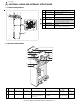
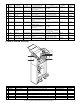
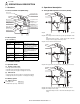
1 : Jan. 9 2004 [3] EXTERNAL VIEWS AND INTERNAL STRUCTURES 1. External components 1 2 3 No. 1 4 Description Paper feed tray 2 Paper guide 1 3 4 Top cover Operator panel 1 5 Paper guiding section (Lever) Front cover 1 6 Function Place blank or printed sheets to be inserted in this tray. Adjust this guide according to the paper size. Open this cover to clear a paper jam. Used to staple and punch during off-line. (The same operation can be made with the operation panel of the main unit.
No.
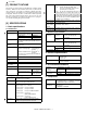
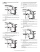
1 : Jan. 9 2004 [4] OPERATIONAL DESCRIPTION 1. Structure 3. Operational description A. Cross-sectional view (Main body) A. Through-mode operation of inserter (Online) Pickup roller Paper feed roller Separation roller Empty sensor Registration roller Registration sensor Timing sensor Vertical transport roller Paper exit sensor Horizontal transport roller 1 Reverse roller Horizontal transport roller 2 Reverse sensor Step 01: The inserter receives an operation command sent by the main unit.
B. Normal paper feed operation of inserter (online/ offline) Step 09: The paper feed motor starts to rotate in the forward direction. The registration rollers and vertical transport rollers rotate. Step 10: The timing sensor detects the leading edge of the sheet. [Paper loading] Step 11: The leading edge of the sheet passes between the vertical transport rollers. Step 12: When sheet transport needs to be suspended for adjusting the space between sheets, the paper feed motor stops to stop the sheet.
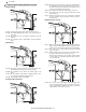
1 : Jan. 9 2004 1 C. Reverse paper feeding operation of inserter [Paper loading] Step 09: The paper feed motor starts to rotate in the forward direction. The registration rollers and vertical transport rollers rotate. If the sheet is the first sheet, the flapper solenoid in the reverse section is turned ON at this point of time. Step 10: The timing sensor detects the leading edge of the sheet. Step 11: The leading edge of the sheet passes between the vertical transport rollers.
4. Offline mode setting [Exiting from reverse section] A. How to set punching mode The figure below shows the operator panel. Start LED Punch LED Start switch Punch switch Setting procedure: Step 01: Place a sheet in the tray. Step 02: Press the PUNCH switch on the operator panel. Step 17: When the reverse motor has completely stopped, the reverse motor starts to reverse, and the transport motor starts. Step 18: The reverse sensor is turned ON, and detects the leading edge of the sheet.
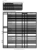
1 : Jan. 9 2004 The correspondence between the punching/stapling mode settings and LEDs is shown below. Punch LED ❍ ❍ ❍ ❍ ● ● ● ● LED1 ● ❍ ❍ ❍ ❍ ● ❍ ❍ Staple mode LEDs LED2 LED3 LED4 ❍ ❍ ❍ ● ❍ ❍ ❍ ● ❍ ❍ ❍ ● ❍ ❍ ❍ ❍ ❍ ❍ ● ❍ ❍ ❍ ● ❍ Stapling mode 1-point stapling at back 2-point stapling 1-point stapling at front Saddle stapling (saddle stitching) Punching Punching + 1-point stapling at back Punching + 2-point stapling Punching + 1-point stapling at front ∗ ●: means "Lit." 5.
6. Paper jam/error detection A.
1 : Jan. 9 2004 [5] ADJUSTMENTS 1. Paper width detection level setting (adjustment) LED 6 LED 5 PUNCH key 1) 2) LED 4 Operator panel LED 2 STAPLE key LED 1 START key Enter the diag mode. 4) Press START key. (The selected diag mode is executed.) Press and hold PUNCH key and START key, and turn on the power of the main unit. 5) Check that LED2 is flashing, and set the paper guide to the max. width position. The LCD display of the main unit turns on and off, then turns on again.
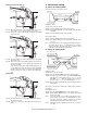
[6] DISASSEMBLY AND ASSEMBLY B. Torque Limiter & Separation Roller 1) Open the top cover. 1. Paper Feed Separation Unit 2) Remove the maintenance cover. A. Pickup Roller & Paper Feed Roller 1) Open the top cover 3) Turn the separation roller unit to remove. 2) Remove the maintenance cover. 4) Remove the torque limiter and the separation roller. A: Torque limiter 3) Turning the paper feed unit, remove the paper feed roller guide.
1 : Jan. 9 2004 2. Paper Feed Unit A: Horizontal pass roller 1 A. Horizontal Pass Roller 1 and Registration Roller B: Registration roller 1) Open the top cover. 2) Open the mount cover. B A B. Horizontal Pass Roller 2 and Timing Roller 1) Open the top cover. 2) Remove the front cover and rear cover. 3) Remove the front cover. 3) Disconnect the connector to remove the operating unit. 4) Remove the rear cover.
1 : Jan. 9 2004 5) Remove the finisher latch cover. 5) Remove the cover bracket. A: Horizontal pass roller 2 B: Timing roller B A D. Paper Guide C. Reverse Roller 1) Open the top cover. 2) Remove the front cover and rear cover. 3) Remove the finisher fixing bolt to remove the finisher positioning stay unit. 1 4) Remove the reverse supports and E-rings to remove the reverse unit.
3. Drive Unit 4. Other Parts A. Belts A. Sensors 1) Open the top cover. 2) Remove the rear cover. B. Gears 1) Open the top cover. 2) Remove the rear cover. 3) Disconnect the connector to remove the drive unit. 5. Note on assembly A. Reverse flapper solenoid adjustment 1) Rotate the solenoid lever (LVR-FM-SOL) fully clockwise.
[7] MAINTENANCE 1. Maintenance list ✕ Check ❍ Cleaning ▲ Replace ∆ Adjust (Clean, replace, and adjust, if necessary.) Unit name Paper separate section Transport section Drive section Others ✩ Lubricate AR-M550U/M550N (PM: 250K) AR-M620U/M620N (PM: 300K) No.
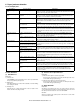
[8] TROUBLESHOOTING Problem Case1 Case2 Case3 Case4 Problem Case1 The inserter does not perform at all when the main switch of the main unit is turned ON. Cause Loose contact with the main unit Check and Check that each connector is firmly remedy connected. Cause Loose contact of the connector terminal of the wire (interface harness) connecting with the main unit Check and Check continuity in between the remedy connector terminals.
1 : Jan. 9 2004 Problem Case1 Case2 Case3 Problem Case1 Case2 Case3 1 Case4 Problem Case1 Case2 Tray alarm is displayed on the system display. Cause Sub-tray pulling detection sensor fault Check and Measure a voltage on TP14 on the remedy controller PCB and check that 5 V is observed when the sub-tray is in place, and that 1 V or less is observed when the sub-tray is pulled out. Replace the sensor if the measured voltage exceeds these ranges.
[9] ELECTRICAL SECTION 1.
2. Circuit Description A. Outline This circuit controls paper feed, transport, reverse, and delivery. This circuit consists of the following divisions: managing signals from the sensors, the switches, and the main unit; driving the motors, the solenoid, and the clutch; the CPU and associated circuits. B.
C. Circuit Detail (1) Communication Circuit <1> TxD signal <2> RxD signal Main Unit Main Unit Finisher Finisher This circuit communicates with the main unit and the finisher. TxD0 and TxD1 are data signals transmitted from the main unit and the finisher to the inserter. RxD0 and RxD1 are data signals transmitted from the inserter to the main unit and the finisher. Logical 1 is represented by +5V, and logical 0 is represented by 0V.
Paper Exit Sensor Reverse Unit Open/Closed Sensor Chassis Cover Open/Closed Sensor <2> Paper Exit Sensor (HI_SEN) HI_SEN uses the photointerrupter integrated with an LED and a phototransistor. The sensor detects a sheet with the lever actuator interrupting the light path of the photointerrupter. The signal is transmitted to the CPU (IC6-Pin106) through the noise filters (R25,C9). The signal input to the CPU follow the logic: "L" when a sheet is detected, "H" when not detected.
Paper Width Detection Potentiometer Tray Sensor Sub Tray Drawn Detection Sensor Sub Tray Folded Detection Sensor <9> Paper Width Detection Potentiometer (T_VR) <11> Sub Tray Drawn Detection Sensor (TH_SEN) T_VR is a potentiometer. TH_SEN uses the photointerrupter integrated with an LED and the phototransistor in one unit. The paper width is detected using the output voltage, which may vary depending on the potentiometer's knob position.
(3) Motor Drive Circuits <1> Paper Feed Motor Drive Circuit (K_MOT) Paper Feed MOT Not Mounted This circuit rotates/stops K_MOT and controls its rotational direction and the motor current. The circuit consists of the CPU (IC6), the D/A converter (IC13), the constant-current chopper driver IC (IC9), and other elements. The analog signal from the D/A converter (IC13-Pin11) is divided into the constant voltage by R53 and R54. The divided voltage is applied to IC9-Pin9,11 to set the motor current.
(4) Flapper Solenoid and Registration Clutch Drive Circuit (F_SOL and R_CL) Flapper SOL Registration CL This circuit controls the flapper solenoid operation and the registration clutch engagement. When the signal F_SOL is "H", Q2 turns on to activate the solenoid. Similarly, when the signal R_CL is "H", Q3 turns on to engage the clutch. The flapper solenoid drive signal is the PWM signal. At the beginning of the solenoid activation, the signal is adjusted to set the solenoid at 100% duty cycle.
(7) Inrush Current Limiting Circuit JAM cover open/closed This circuit limits an inrush current flowing into the regeneration capacitor included in the motor drive system to a certain value or less. The circuit consists of the PTC thermistor (PTH2) that limits a current and the FET (Q11) that allows a steady current flowing. When the JAM cover open/closed detection switch is closed, the cathode voltage of ZD1 starts rising to the zener voltage according to the time constant of R55 and C46.
(9) Operator Panel Circuit This is the circuit of the operator panel board. The operator panel drive board turns each of the LED1-6 on or off, and detects weather each of the PSW1-3 is on or off.
Memo
Memo
LEAD-FREE SOLDER The PWB’s of this model employs lead-free solder. The “LF” marks indicated on the PWB’s and the Service Manual mean “Lead-Free” solder. The alphabet following the LF mark shows the kind of lead-free solder. Example: Lead-Free 5mm Solder composition code (Refer to the table at the right.
CAUTION FOR BATTERY REPLACEMENT (Danish) ADVARSEL ! Lithiumbatteri – Eksplosionsfare ved fejlagtig håndtering. Udskiftning må kun ske med batteri af samme fabrikat og type. Levér det brugte batteri tilbage til leverandoren. (English) Caution ! Danger of explosion if battery is incorrectly replaced. Replace only with the same or equivalent type recommended by the manufacturer. Dispose of used batteries according to manufacturer’s instructions.
All rights reserved. Printed in Japan. No part of this publication may be reproduced, stored in a retrieval system, or transmitted, in any form or by any means, electronic; mechanical; photocopying; recording or otherwise without prior written permission of the publisher. Trademark acknowledgements • Microsoft® Windows® operating system is a trademark or copyright of Microsoft Corporation in the U.S.A. and other countries. • Windows® 95, Windows® 98, Windows® Me, Windows NT® 4.