PG-M20S PG-M20X SERVICE MANUAL SERVICE-ANLEITUNG S72N3PG-M20XU DIGITAL MULTIMEDIA PROJECTOR DIGITALER MULTIMEDIA PROJEKTOR PG-M20S PG-M20X MODELS MODELLE AN-60KT In the interests of user-safety (Required by safety regulations in some countries) the set should be restored to its original condition and only parts identical to those specified should be used. Im lnteresse der Benutzersicherheit (erforderliche Sicherheitsregeln in einigen Ländern) muß das Gerät in seinen Originalzustand gebracht werden.
PG-M20S PG-M20X Specifications Product type Digital Multimedia Projector Model PG-M20X/PG-M20S Video system NTSC 3.58/NTSC 4.43/PAL/PAL-M/PAL-N/PAL 60/SECAM/ DTV480I/DTV480P/DTV720P/DTV1080I Display method Single Chip Digital Micromirror Device™ (DMD™) by Texas Instruments DMD panel Panel size: 0.7" (17.8 mm), 1 chip XGA DMD(PG-M20X)/0.55"(14.0mm)",1 chip SVGA DMD(PG-M20S) No. of dots: 786,432 dots (1,024 [H] × 768 [V])(PG-M20X)/480.000 dots (800[H] × 600[V])(PG-M20S) Lens 1–1.2 × zoom lens, F1.75–2.
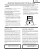
PG-M20S PG-M20X IMPORTANT SERVICE SAFETY NOTES (for USA) Ë Service work should be performed only by qualified service technicians who are thoroughly familiar with all safety checks and servicing guidelines as follows: » Use an AC voltmeter with sensitivity of 5000 ohm per volt., or higher, sensitivity to measure the AC voltage drop across the resistor (See Diagram). » All checks must be repeated with the AC plug connection reversed.
PG-M20S PG-M20X NOTE TO SERVICE PERSONNEL 12345678901234567890123456789012123456789012345 12345678901234567890123456789012123456789012345 NOTE POUR LE PERSONNEL D’ENTRETIEN 12345678901234567890123456789012123456789012345 UV-RADIATION PRECAUTION 12345678901234567890123456789012123456789012345 12345678901234567890123456789012123456789012345 PRECAUTION POUR LES RADIATIONS UV 12345678901234567890123456789012123456789012345 12345678901234567890123456789012123456789012345 The light source, metal halide lamp,
PG-M20S PG-M20X 12345678901234567890123456789012123456789012345 12345678901234567890123456789012123456789012345 12345678901234567890123456789012123456789012345 12345678901234567890123456789012123456789012345 1234567890123456789012345678901212345678901234 UV-RADIATION PRECAUTION (Continued) 1234567890123456789012345678901212345678901234 1234567890123456789012345678901212345678901234 PRECAUTION POUR LES RADIATIONS UV (Suite) 12345678901234567890123456789012123456789012345 123456789012345678901234567890121
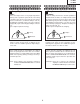
PG-M20S PG-M20X WARNING: High brightness light source, do not stare into the beam of light, or view directly. Be especially careful that children do not stare directly in to the beam of light. WARNING: TO REDUCE THE RISK OF FIRE OR ELECTRIC SHOCK, DO NOT EXPOSE THIS UNIT TO MOISTURE OR WET LOCATIONS. CAUTION The lighting flash with arrowhead within a triangle is intended to tell the user that parts inside the product are risk of electric shock to persons. RISK OF ELECTRIC SHOCK.
PG-M20S PG-M20X Precautions for using lead-free solder 1 Employing lead-free solder "Input and key PWBs" of this model employs lead-free solder. The LF symbol indicates lead-free solder, and is attached on the PWBs and service manuals. The alphabetical character following LF shows the type of lead-free solder. Example: LFa Indicates lead-free solder of tin, silver and copper. 2 Using lead-free wire solder When fixing the PWB soldered with the lead-free solder, apply lead-free wire solder.
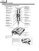
PG-M20S PG-M20X Location of Controls Projector (Front and Top View) LAMP REPLACEMENT indicator TEMPERATURE WARNING indicator Illuminates in green normally. Replace the lamp when the indicator illuminates in red. Illuminates in green normally. When the internal temperature rises, this indicator will illuminate in red. POWER indicator Illuminates in red, when the projector is in standby. When the power is turned on, this indicator will illuminate in green.
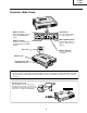
PG-M20S PG-M20X Projector (Side View) INPUT 1 terminal USB terminal Port for DVI digital, computer RGB, and COMPONENT signals. For connecting a computer using a USB cable. INPUT 2 terminal INPUT AUDIO terminal Shared audio terminal for INPUT 1, INPUT 2, and INPUT 3. Terminal for connecting video equipment with an S-VIDEO terminal. AC socket INPUT 3 terminal For connecting video equipment.
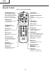
PG-M20S PG-M20X Remote Control Remote control signal transmitter FORWARD/BACK button POWER button Moves forward or backwards when connected to a computer using a USB cable. Same as the [Page Down] and [Page Up] keys on a computer keyboard. Turns the power on or off. ENLARGE (Enlarge/Reduce) buttons For enlarging or reducing part of the image. AV MUTE button For temporarily turning off the sound and picture. FREEZE button For freezing images.
PG-M20S PG-M20X Connection Pin Assignments DVI Digital / Analog INPUT 1 port : 29 pin connector • DVI Digital INPUT 9 ••••••••• 1 2 •••• Pin No. 1 2 3 4 5 6 7 8 9 10 11 12 13 14 15 ~ • • • • • • • • • 16 ~ •••• 7 8 C1 C2 C4 C5 C3 17 24 18 •••• ~ •••• 23 • DVI Analog RGB Input Pin No.
PG-M20S PG-M20X Dimensions Rear View Side View Top View 12 9/16 (318.3) Side View 11 15/16 (303) 8 3/4 (223) 8 5/8 (219) 5 1/16 (128) Front View 1 1/2 3 1/4 3 (38.7) (76.1) (82.9) 3/8 1 (34.2) 4 9/16 (115.5) 7 11/16 (195) 3 1/4 (82.5) 3/16 2 (55.5) 3 1/ 8 (80) Bottom View 2 3/8 (60) 5/16 (7.5) 4 1/ 8 (104) 10 5/16 (261.
PG-M20S PG-M20X REMOVING OF MAJOR PARTS 1. Removing the top panel 1-1. 1-2. 1-3. 1-4. 1-5. 1-6. Detach the terminal block cover. Remove the five lock screws from the top panel. Press the right side of the bottom body to undo the hook. Press the left side of the bottom body to undo the hook. Press the front of the bottom body to undo the hook. Get the top panel loose from the bottom body. Slightly raise the front of the top panel and disconnect the speaker connector. 2.
PG-M20S PG-M20X 3. Removing the operation PWB 3-1. Remove the two lock screws from the operation PWB and slightly raise this PWB. 3-2. Disconnect the connectors. 4. Removing the optical mechanism 4-1. 4-2. 4-3. 4-4. Remove the two lock screws from the lamp socket. Raise the two lamp socket lead fixtures. Disconnect the connectors. Remove the six lock screws from the optical mechanism.
PG-M20S PG-M20X 5. Removing the other PWBs 5-1. 5-2. 5-3. 5-4. 5-5. 5-6. Disconnect the connectors. Remove the four lock screws from the power PWB. Remove the lock screw from the ballast PWB unit. Remove the three hex support screws from the input PWB. Remove the lock screw from the terminal block cover. Remove the three lock screws from the PFC PWB.
PG-M20S PG-M20X 6. Removing the formatter PWB 6-1. Disconnect the connector. 6-2. Remove the two lock screws from the heat sink. 6-3. Remove the four lock screws from the backer plate assembly, and detach the formatter PWB. Note: The DMD (Digital Micromirror Device) unit is easily affected by static electricity. In handling this unit, be sure to wear a wristband or take other anti-static measure.
PG-M20S PG-M20X * Precautions in setting up the DMD (Digital Micromirror Device) unit Before connecting the formatter PWB to the optical engine, take the following steps. Look at the voltage rank marking that is on the DMD itself. Referring to this marking, set the DIP switches on the formatter PWB. And connect this PWB to the optical engine. Wrong settings will adversely affect the system performance. Voltage rank marking This sample is "C".
PG-M20S PG-M20X Outline of the optical unit Relay lenses Rod lens Reflector Projection lens Lamp UV/IR filter Prism DMD chip Item Lamp UV/IR filter Color wheel Rod lens Relay lenses Reflector Prism DMD chip Projection lens Color wheel Function Light source. DC-driven high-pressure mercury vapor lamp. Used to absorb ultraviolet and infrared rays. Used to let the source light through the color filter and to separate it into R, G and B colors. Used to make for uniform light beams.
PG-M20S PG-M20X RESETTING THE TOTAL LAMP TIMER Resetting the Lamp Timer Reset the lamp timer after replacing the lamp. 1 Connect the power cord. • Plug the power cord into the AC socket of the projector. 2 AC socket Reset the lamp timer. • While pressing , , and tor, press simultaneously on the projec- POWER button on the projector. • ÒLAMP 0000HÓ is displayed, indicating Adjustment buttons ( |) that the lamp timer is reset.
PG-M20S PG-M20X How to Release the System Lock Turn on the power. If the system lock is applied, the system-resetting screen appears. Press the following keys in this order. MENU → ENTER → ENTER → MENU → UNDO → UNDO → MENU After pressing the MENU key first, press the remaining six keys within 10 seconds.
PG-M20S PG-M20X ELECTRICAL ADJUSTMENT No. Adjustment Items Adjustment Conditions Adjustment Procedures 1 Initialization of EEPROM 1. Turn on the power (the lamp lights up) and warm up the system for 15 minutes. 1. Carry out the following setting. Press SW2001 to enter the process mode, and execute S2 on SSS menu. 2 Adjustment of CW index 1. Signal input: 64-step color bar 2. Select the following group and subject. Group: DLP Subject: Select CW-INDEX. 1. Feed the signal to INPUT 1. 2.
PG-M20S PG-M20X No. Adjustment Items Adjustment Conditions Adjustment Procedures 6 Adjustment of NTSC color saturation 1. Feed the internal 8ch (split color bar) signal. 2. Select the following group and subject. Group: VIDEO Subject: N-COLOR 1. Confirm the fixed value. Fixed value: 59 7 Adjustment of PAL 1. Feed the PAL color bar signal. color saturation 2. Select the following group and subject. Group: VIDEO Subject: P-COLOR 1. Confirm the fixed value.
PG-M20S PG-M20X No. Adjustment Items Adjustment Conditions Adjustment Procedures 13 Automatic adjustment of video white balance 1. Feed the 50% gray pattern signal (NTSC, burst signal). 2. Select the following group and subject. Group: DLP Subjects: V-R1-GAIN (Red) V-B1-GAIN (Blue) 1. Adjust V-R1-GAIN and V-B1-GAIN so that x-value should be 265±3 and yvalue should be 298±3. 14 Automatic adjust- 1. Feed the 50% gray pattern signal ment of DTV white (480I, color difference signal). balance 2.
PG-M20S PG-M20X No. Adjustment Items Adjustment Conditions Adjustment Procedures 22 Automatic sync operation 1. Receive the phase checking pattern signal. 1. Confirm that Clock, Phase, H-POS and V-POS can be automatically adjusted in the VGA/S-VGA/XGA mode. 23 Confirmation of USB operation Connect the set to a personal computer by USB cable. Using the remote controller, make sure that feed and return operations are effective on the display of the personal computer. 24 Factory settings 1.
PG-M20S PG-M20X » Entering the adjustment process mode There are follwing two methods. » Press the SW2001 on the KEY PWB unit. » Press the follwing keys in this order.
PG-M20S PG-M20X Group Sample Pattern PATTERN Sub Group Adjust CVIC CVIC-PROGRSSIVE Subject RGB RGB(50) CROSS FOCUS SETP COLOR CHR MODE IP MDSW PTGSW C-TESTSW C-ILG-LY C-MOD-LY C-VE-LV ENH-PLUS ENH-MINUS DFC ENH-PLUS ENH-MINUS DFC MODE ENH-GAIN ENH-PLUS CUBIC-RGB CUBIC-VEDEO YNR-LEVEL YNR-K YNR-FSEL CNR-LEVEL CNR-K CNR-FSEL CNR-FILSW TESTSW ENABLE MV-F VDDTP RED YELLOW GREEN CYAN BLUE MAGENTA TABLE IPL IPL2 E2PROM ADR RD/WR USB-MODE CVIC-ENHANCE-VIDE CVIC-ENHANCE-HTTV CVIC-ENHANCE-RGB CVIC-SCREEN C
PG-M20S PG-M20X How to write in a Serial number Install the new program for the software into your PC a.This software is downloaded from home page of SHARP intranet. http://172.24.145.13/tcg-qrc/prj/prj-e.asp NAME:USB to Sirial Driver program. STEP 1 Set-up for USB Serial Driver (Refer to "Installation Process and advice.doc" file.) STEP 2 Call the adjustment process mode, and select the sub-group "SPECIAL" and the adjustment item "USB-MODE". Change the USB MODE value from 0 to 1.
PG-M20S PG-M20X TROUBLE SHOOTING TABLE Checking of Basic Operation Does the POWER LED light up or flicker in red or green? No Go to "Checking of Power Unit". Yes Does the set operate by the set's key or the remote controller's power key? No Go to "Checking of Sub-microcomputer and Its Periphery" Yes Does the cooling fan rotate and does the lamp light up? No Go to "Checking of Lamp Lighting-up" Yes Is the user menu displayed? No Check the formatter circuit and its periphery.
PG-M20S PG-M20X Checking of Power Unit Are connectors in the power unit completely inserted? No Insert the connectors CN702, CN704, CN7003, CN7001, CN7004 and CN7101 completely. No Close the lamp door completely by screws. No Replace the fuse as well as its harness. Yes Is the lamp door closed completely? Yes Does the temperature fuse function? Yes Is AC voltage applied across relay RL701? No Replace F701.
PG-M20S PG-M20X Lamp failure to light up (formatter unit) Is any of the SC9001, SC9002, P9002 and P9003 connectors disconnected or in poor contact? Yes Insert the connectors completely. No Is there the specified voltage at pin (15) of SC9002? Yes Is there the 180-Hz pulse signal at pin (1) of P9002? No Is there the specified voltage at pin (11) of P3002? No Check the fan circuit (near IC2101) on the KEY PWB. Yes Yes Check the lamp and ballast unit.
PG-M20S PG-M20X Lamp does not light up. Yes Is the cooling fan rotating? No Check the power circuit or the fan circuit on the key/input PWB. No Check IC3101, the motor driver circuit and their periphery. Check the waveform of SC3101. Yes Is the color wheel rotating sound heard? Yes Normal Replace the color wheel. Is the lamp discharging sound heard? Yes Abnormal Check the formatter PWB. Check the socket No No Replace the lamp.
PG-M20S PG-M20X Checking of Sub-microprocessor and Its Periphery Does POWER LED flicker in red (for 2 seconds)? No Yes Is there B+3.3V output at pins (12) and (13) of CN3701? Yes No Is there 6V output at pins (5) and (6) of P2003? No Go to "Checking of PC I/F Unit", and check the flexible connector. Communication error of sub-microprocessor (KEY) and SH microprocessor (PC I/F unit) Pins (20) and (21) of P2001. Check Q2001 thru Q2004 and IC2001. Yes Go to "Checking of Power Unit" Is Bu+6.
PG-M20S PG-M20X Checking of Low-pass Filter Circuit Is video signal is inputted to pins (4), (8) and (12) of IC3851? No Check pins (4), (8) and (12) of SC3001. Normal Yes Check Q3854 and Q3855. Is video signal inputted to pins (24), (21) and (17) of IC3851? Check the PC I/F unit. Check DVI (analog) input. No IC3851 is defective. If the picture quality is abnormal, check whether or not the following voltages are outputted to pin (28) of IC3851. 0.3 V for 480i, 1 V for 720p, 1080i, Check IC301.
PG-M20S PG-M20X Checking of DTV (480i Component Input) Feed the 480i component signal in INPUT 1. Select INPUT 1 using the set's key or the remote controller. Select 480i among the special modes on the user menu screen. Go to "Checking of Low-pass Filter Circuit" Yes Yes Is picture outputted? No Confirmation of synchronization. Is Y signal including sync signal inputted to pin (3) of IC3502? No Is the signal type set to the component? Check IC8016 (Video decoder).
PG-M20S PG-M20X Checking of Video Input Feed the composite video signal to INPUT 3. Select INPUT 3 using the set's key or the remote controller. Does the picture appear? Yes Is the picture disturbed? No Are pin(5) (horizontal) and pin(10) (vertical) signals inputted to IC8363 on the PC I/F unit? Yes No No Yes 1 Is the video signal including sync Yes signal inputted to pin (3) of SC3001 on the input PWB? Check IC8363 and IC8025 (CVIC2) and their periphery.
PG-M20S PG-M20X » FORMATTER Unit Abnormal picture Blackout Rainbow-like picture Others No No Go to "Lamp Does Not Light Up." Is signal outputted at pins (3), (5) and (7) of SC9001? No Is the lamp on? Go to "Checking of PC I/F nunit" Yes Trouble with IC9003, IC9006 or their periphery Is any of SC9001, SC9002, P9002 and P9003 connectors disconnected or in poor contact? Yes Insert the connectors completely. No Check the regulator ICs on the input PWB and KEY PWB.
PG-M20S PG-M20X » PC I/F Unit-1/12 Checking of PC PWB 0 Yes Is the user menu displayed? No Check the onscreen display. Check the RGB input. Check the component input. Check the video input. Check the DVI digital input. PCカードのチェック Check the PC card.
PG-M20S PG-M20X » PC I/F Unit-2/12 Checking of Onscreen Display Is the user menu displayed normally by the MENU key? Yes The onscreen display is normal. No Enter the process menu and select PATTERN. Then select the COLOR pattern. Is the onscreen display color normal? No Adjust the DLP system in the process adjustment mode. Yes 0 Make STEP signal selection. Is the STEP signal normal? Yes Rewrite the onscreen display data.
PG-M20S PG-M20X » PC I/F Unit-3/12 Checking of RGB Input Feed the sync separation type analog RGB signal to INPUT 1. 1 Select INPUT 1 using the set's key or the remote controller. 2 Does the picture appear? No Go to "Confirmation of Video Input". Yes Is the picture disturbed? Yes Go to "Checking of Sync Signal". No 3 Do the three colors R, G and B appear? No Go to "Checking of RGB Signal". Yes Carry out the AUTOSYNC process.
PG-M20S PG-M20X » PC I/F Unit-4/12 Confirmation of Video Input Make "Confirmation of Input Signal Setting". Is there video signal at the land of C8070? No Is there signal at the terminal C2 of P8001 (DVI connector)? Yes Yes Somewhere in the signal route is defective. Check the capacitors and resistors between the connector and IC8013. Go to "Checking of Sync Signal". IC8025 or IC8013 is defective. The signal source or connector is defective.
PG-M20S PG-M20X » PC I/F Unit-5/12 Checking of Sync Signal Is there the vertical sync signal at pin (11) of IC8363? No Yes Is there the horizontal sync signal at pin (5) of IC8363? No Make confirmation of input signal setting. Yes IC8330, IC8331 or its periphery is defective. Is there the vertical sync signal at TL8131? No Yes Is there the horizontal sync signal at TL8130? No IC8363 is defective.
PG-M20S PG-M20X » PC I/F Unit-6/12 Checking of R, G and B Signals Is the signal type set to RGB? No Yes Set the signal type to RGB. Set the process mode. Select R, G and B individually on the pattern menu. Go to "Checking of GA4 and Its Periphery". For checking the input signal, set the signal generator to gradation signal. Check TL8169, TL8170 and TL8180 by oscilloscope.
PG-M20S PG-M20X » PC I/F Unit-7/12 Checking of GA4 and Its Periphery Select R, G and B individually on the pattern menu in process mode. Is picture outputted appropriately in R, G and B? Yes Checking of GA4 and its periphery ends. No Check pins (72), (52) and (32) of SC8001 by oscilloscope. These signals are MSB of B/G/R. Do the signals selected on the pattern menu match with those checked by oscilloscope? Yes The DLP PWB is defective.
PG-M20S PG-M20X » PC I/F Unit-8/12 Checking of Component Input (except 480I) Feed the component signal to INPUT 1. Select INPUT 1 using the set's key or the remote controller. Is the picture appear? No Go to "Checking of SOG Circuit". Yes 4 Is the color normal? No Is the signal type set at component? No Yes Set the signal type to component. Carry out the process adjustment. 4 Is the contour of picture clear? No IC8013 or IC8025 is defective. Yes The component is normal. End.
PG-M20S PG-M20X » PC I/F Unit-9/12 Checking of SOG Circuit Check pin (2) of IC8365 by oscilloscope. Is the composite sync signal reproduced in correct timing? Yes The SOG circuit is normal. End. No Go to "Confirmation of Input Signal Setting". No Check the land of C8070 by oscilloscope. Is there the Y signal including sync signal? Yes The SOG sync separation circuit (input PWB) is defective.
PG-M20S PG-M20X » PC I/F Unit-10/12 Checking of Video Input Feed the composite video signal to INPUT 3. Select INPUT 3 using the set's key or the remote controller. 5 Is the picture appear? No Go to "Checking of Video Sync Signal". Yes Is there any disturbance in the picture? Yes No Go to "Checking of Video Sync Signal". Carry out the process adjustment. No Is the color normal? 5 Yes The video input is normal. End.
PG-M20S PG-M20X » PC I/F Unit-11/12 Checking of Video Sync Signal Check pin (10) of IC8363 by oscilloscope. (Checking of vertical sync signal) Is the vertical sync signal normal? No Yes Check pin (6) of IC8363 by oscilloscope. (Checking of horizontal sync signal) Is the horizontal sync signal normal? No Go to "Confirmation of Input Signal Setting". No IC8015 and its periphery are defective. No IC8015 and its periphery are defective.
PG-M20S PG-M20X » PC I/F Unit-12/12 Checking of DVI Digital Input Feed the DVI digital signal to INPUT 1. Select INPUT 1 for input. Is the picture appear? No Yes Is there any disturbance in the picture? No Yes Is the color normal? No IC8298 and its periphery are defective. Yes The DVI digital input is normal. Check pin (13) of IC8363 for vertical sync signal, and check pin (3) of IC8363 for horizontal sync signal. Are the sync signals normal? No Yes Check R8685 for clock signal.
PG-M20S PG-M20X Technische Daten Produkttyp Digitaler Multimedia-Projektor Modell PG-M20X/PG-M20S Videosystem NTSC 3.58/NTSC 4.43/PAL/PAL-M/PAL-N/PAL 60/SECAM/ DTV480I/DTV480P/DTV720P/DTV1080I Wiedergabeverfahren Single Chip Digital Micromirror Device™ (DMD™) von Texas Instruments DMD-Panel Panel-Größe: 0,7" (17,8 mm), 1 Chip XGA DMD(PG-M20X)/ 0.55"(140.0mm), 1 chip SVGA DMD(PG-M20S) Anzahl der Bildpunkte: 786.432 Bildpunkte (1.024 [H] × 768 [V])(PG-M20X) 480.
PG-M20S PG-M20X HINWEIS FÜR DAS WARTUNGSPERSONAL 12345678901234567890123456789012123456789012345 12345678901234567890123456789012123456789012345 Ë Auswechseln der Lampe ACHTUNG: UV-STRAHLUNG 12345678901234567890123456789012123456789012345 12345678901234567890123456789012123456789012345 12345678901234567890123456789012123456789012345 Hinweis: Da die Lampe während des Betriebs sehr heiß wird, sollte die Lampe erst ausgewechselt werden, nachdem das Gerät mindestens eine Stunde ausgeschaltet war, damit die
PG-M20S PG-M20X Vorsichtsmaßregeln für bleifreien Lötzinn 1 Verwendung von bleifreiem Lötzinn Die "Eingangs-und Schlüssel-Platine" dieses Modells verwendet bleifreien Lötzinn. Das LF-Symbol zeigt bleifreien Lötzinn an und ist an den Platinen und Wartungsanleitungen angebracht. Der Buchstabe nach LF zeigt den Typ des bleifreien Lötzinns an. Beispiel: LFa Zeigt bleifreien Lötzinn aus Zinn, Silber und Kupfer an.
PG-M20S PG-M20X Bedienelemente Projektor (Vorder- und Draufsicht) LAMP-Anzeige (Lampenaustausch) TEMP.-Anzeige (Temperaturwarn) Leuchtet normalerweise grün. Die Lampe austauschen, wenn die Anzeige rot leuchtet. Leuchtet normalerweise grün. Wenn die interne Temperatur ansteigt, leuchtet diese Anzeige rot. POWER-Anzeige (Netz) Leuchtet rot, wenn sich der Projektor im Bereitschaftsbetrieb befindet. Wenn die Stromversorgung eingeschaltet ist, leuchtet diese Anzeige grün.
PG-M20S PG-M20X Projektor (Seitenansicht) USB-Anschluss INPUT 1-Anschluss Schnittstelle für DVI Digital-, Computer RGB- und COMPONENT-Signale. Für den Anschluss eines Computers mittels USBKabel. INPUT 2-Anschluss INPUT AUDIOAnschluss Anschluss für ein Videogerät mit einem S-VIDEO-Anschluss. Gemeinsam genutzter Audioanschluss für INPUT 1, INPUT 2 und INPUT 3. Netzanschluss INPUT 3-Anschluss Für den Anschluss eines Videogerätes.
PG-M20S PG-M20X Fernbedienung Fernbedienungssignal-Sender FORWARD/BACK-Taste POWER-Taste Schaltet nach vorne oder hinten, wenn ein Computer mittels eines USB-Kabels angeschlossen ist. Wie die [Page Up]- und [Page Down]Tasten auf der Computer-Tastatur. Schaltet die Stromversorgung ein oder aus. ENLARGE-Tasten (Vergrößern/ Verkleinern) Für das Vergrößern oder Verkleinern eines Bildteils. AV MUTE-Taste Für das vorübergehende Ausschalten des Tons und des Bildes.
PG-M20S PG-M20X Pin-Belegung DVI Digital-/Analog-EINGANG 1-Port: 29 Pin-Anschluss • DVI-Digital-EINGANG 9 ••••••••• 1 2 •••• Pin-Nr. 1 2 3 4 5 6 7 8 9 10 11 12 13 14 15 ~ • • • • • • • • • 16 ~ •••• 7 8 C1 C2 C4 C5 C3 17 24 18 •••• ~ • • • • 23 • DVI-Analog-RGB-Eingang Pin-Nr. 1 2 3 4 5 6 7 8 9 10 11 12 13 14 15 Signal Nicht angeschlossen Nicht angeschlossen Nicht angeschlossen Nicht angeschlossen Nicht angeschlossen DDC-Taktgeber DDC-Daten Vertikales Sync.
PG-M20S PG-M20X Abmessungen Ansicht von hinten Einheiten: Zoll (mm) Ansicht von oben Ansicht von der Seite 12 9/16 (318,3) Ansicht von der Seite 11 15/16 (302,5) 8 3/4 (223) 8 5/8 (219) 5 1/16 (128) Ansicht von vorne 3 3 1/4 1 1/2 (38,7) (76,1) (82,9) 3/8 1 (34,2) 4 9/16 (115,5) 7 11/16 (195) 3 1/4 (82,5) 2 3/16 (55,5) 3 1/8 (80) Ansicht von unten 2 3/8 (60) 5/16 (7,5) 4 1/8 (104) 10 5/16 (261,5) 56
PG-M20S PG-M20X ENTFERNEN DER HAUPTTEILE 1. Ausbau der Oberabdeckung 1-1. 1-2. 1-3. 1-4. 1-5. 1-6. Die Klemmenblock-Abdeckung entfernen. Die fünf Sperrschrauben von der Oberabdeckung entfernen. Die rechte Seite des Unterteils drücken, um den Haken zu lösen. Die linke Seite des Unterteils drücken, um den Haken zu lösen. Die vordere Seite des Unterteils drücken, um den Haken zu lösen. Die Oberplatte vom Unterteil lösen.
PG-M20S PG-M20X 3. Ausbau der Betriebs-Platine 3-1. Die zwei Sperrschrauben von der Betriebs-Platine entfernen, und dann die Platine leicht anheben. 3-2. Die Steckverbinder abtrennen. 4. Ausbau des Optikmechanismus 4-1. 4-2. 4-3. 4-4. Die beiden Sperrschrauben von der Lampenfassung entfernen. Die beiden Lampenfassungs-Leitungsbefestigungen anheben. Die Steckverbinder abtrennen. Die sechs Sperrschrauben vom Optikmechanismus entfernen.
PG-M20S PG-M20X 5. Ausbau der anderen Platinen 5-1. 5-2. 5-3. 5-4. 5-5. 5-6. Die Steckverbinder abtrennen. Die vier Sperrschrauben von der Betriebsstrom-Platine entfernen. Die Sperrschraube von der Vorschaltdrossel-Platineneinheit entfernen. Die drei Sechskant-Halteschrauben von der Eingangsplatine entfernen. Die Sperrschraube von der Klemmenblock-Abdeckung entfernen. Die drei Sperrschrauben von der PFC-Platine entfernen.
PG-M20S PG-M20X 6. Ausbau der Formatierer-Platine 6-1. Die Steckverbinder abtrennen. 6-2. Die beiden Sperrschrauben von der Wärmesenke entfernen. 6-3. Die vier Sperrschrauben von der Rückhalteplatten-Bügel entfernen, und die Formatierer-Platine abnehmen. Hinweis: Die DMD(Digital-Mikrospiegel-Vorrichtung)-Einheit wird leicht durch statische Elektrizität beeinflusst. Beim Umgang mit diesem Gerät immer ein statikableitendes Armband tragen oder andere Maßnahmen gegen Statik treffen.
PG-M20S PG-M20X * Vorsichtsmaßregeln zur Einrichtung der DMD(Digital-Mikrospiegel-Vorrichtung)-Einheit Vor dem Anschließen der Formatierer-Platine an den Optikapparat die folgenden Schritte ausführen. Die SpannngsrangMarkierung am DMD selber prüfen. Entsprechend dieser Markierung die DIP-Schalter an der Formatier-Platine einstellen. Danach diese Platine an den Optikapparat anschließen. Falsche Einstellungen beeinträchtigen die Systemleistung. Spannungsstand-Markierung Diese Probe ist "C".
PG-M20S PG-M20X Kurzbeschreibung des Optikapparats Relaislinsen Stablinse Reflektor Projektionsobjektiv Lampe UV/IR-Filter Prisma DMD-Chip Gegenstand Lampe UV/IR-Filter Farbrad Stablinse Relaislinsen Reflektor Prism DMD-Chip Projektionsobjektiv Farbrad Funktion Lichtquelle. Gleichstrombetr iebene Hochdr uckQuecksilberdampflampe. Zur Absorption von Ultraviolett- und Infrarotstrahlen. Dient zum Durchlassen der Lichtquelle durch den Farbfilter und Aufspalten in die Farben R, G und B.
PG-M20S PG-M20X RÜCKSTELLUNG DES LAMPEN-TIMERS Den Lampen-Timer nach dem Lampenaustausch zurückzustellen. 1 Das Netzkabel anschließen. • Das Netzkabel am Netzanschluss des Projektors anschlie§en. 2 Den Lampen-Timer zurückstellen. • Whrend , und Netzanschluss auf dem P r o j e k t o r g l e i c h ze i t i g g e d r ck t w i r d , POWER-Taste auf dem Projektor drcken. • ÒLAMPE 0000HÓ erscheint und zeigt damit Einstelltasten (", |) an, dass der Lampen-Timer zurckgestellt ist.
PG-M20S PG-M20X WARTUNGSANZEIGEN ■ Die Warnleuchten auf dem Projektor weisen auf Fehlfunktionen im Projektor hin. ■ Falls ein Problem auftritt, leuchtet entweder die Temperaturwarn-Anzeige oder die Lampenaustausch-Anzeige rot auf und die Stromversorgung wird ausgeschaltet. Nach dem Ausschalten des Gerätes den unten aufgeführten Schritten folgen. TemperaturwarnNetz- Anzeige Anzeige Über die LampenaustauschAnzeige ■Wenn die Lampe Lampenaustausch 1.
PG-M20S PG-M20X Freigabe der Systemsperre Das Gerät einschalten. Wenn die Systemsperre aktiviert wird, erscheint die System-Nullstellungsanzeige. Danach sind die folgenden Tasten in der vorgeschriebenen Reihenfolge zu betätigen. MENU → ENTER → ENTER → MENU → UNDO → UNDO → MENU Zuerst die MENU-Taste drücken, dann die verbleibenden Tasten innerhalb von 10 Sekunden betätigen.
PG-M20S PG-M20X ELEKTRISCH EINSTELLUNG Nr. Einstellposten Einstellbedingungen Einstellverfahren 1 Initialisierung des EEPROM 1. Das Gerät einschalten (Lampe leuchtet auf) und das System für 15 Minuten aufwärmen lassen. 1. Folgende Einstellungen ausführen. SW200 drücken, um in den Prozeßmodus einzutreten, dann S2 im SSS-Menü ausführen. 2 Einstellung für CW-Index 1. Signaleingang: Farbbalken mit 64 Abstufungen 2. Die nachfolgende Gruppe bzw. die Position wählen.
PG-M20S PG-M20X Nr. Einstellposten Einstellbedingungen 1. Das interne 8-Kanal-Trennsignal zuführen. 2. Die nachfolgende Gruppe bzw. die Position wählen. Gruppe: VIDEO Posten: N-COLOR Einstellverfahren 6 Einstellung der NTSCFarbsättigung 7 Einstellung der 1. Das PAL-Farbbalkensignal PAL-Farbsättigung zuführen. 2. Die nachfolgende Gruppe bzw. die Position wählen. Gruppe: VIDEO Posten: P-COLOR 1. Den festgelegten Wert bestätigen. Festgelegter Wert: 59 8 Einstellung der SECAMFarbsättigung 1.
PG-M20S PG-M20X Nr. Einstellposten Einstellbedingungen Einstellverfahren 13 Automatische Einstellung der VideoWeißbalance 1. Das Grau-Mustersignal (50%) zuführen (NTSC, Burst-Signal). 2. Die nachfolgende Gruppe bzw. die Position wählen. Gruppe: DLP Posten: V-R1-GAIN (Rot) V-B1-GAIN (Blau) 1. V-G1-1 GAIN und V-B1-GAIN so einstellen, daß der x-Wert 265±3 und der y-Wert 298±3 beträgt. 14 Automatische Einstellung der DTV-Weißbalance 1. Das Grau-Mustersignal (50%) zuführen (480I, Farbdifferenzsignal).
PG-M20S PG-M20X Nr. Einstellposten Einstellbedingungen Einstellverfahren 22 Automatischer 1. Das Phasen-Prüfmustersignal Synchronisationsbetrieb empfangen. 1. Sicherstellen, daß Takt, Phase, HPOS und V-POS automatisch im VGA/S-VGA/XGA-Modus eingestellt werden können. 23 Den USB-Betrieb bestätigen. Die Fernbedienung benutzen und sicherstellen, daß der Zuführungsund Rückführungsbetrieb am Computermonitor effektvoll ist. 24 Werkseinstellungen Das Gerät via ein USB-Kabel an einen PVC anschließen.
PG-M20S PG-M20X » Eingabe des Einstellprozeßmodus Es gibt die folgenden zwei Verfahren. » Den SW2001 an der Tastenplatinen-Einheit drücken. » Die folgenden Tasten in der vorgeschriebenen Reihenfolge betätigen.
PG-M20S PG-M20X Gruppe Beispielmuster Untergruppe PATTERN CVIC einstellen CVIC-PROGRSSIVE Gegenstand RGB RGB(50) CROSS FOCUS SETP COLOR CHR MODE IP MDSW PTGSW C-TESTSW C-ILG-LY C-MOD-LY C-VE-LV ENH-PLUS ENH-MINUS DFC ENH-PLUS ENH-MINUS DFC MODE ENH-GAIN ENH-PLUS CUBIC-RGB CUBIC-VEDEO YNR-LEVEL YNR-K YNR-FSEL CNR-LEVEL CNR-K CNR-FSEL CNR-FILSW TBL-NO TESTSW ENABLE MV-F VDDTP RED YELLOW GREEN CYAN BLUE MAGENTA TABLE IPL IPL2 E2PROM ADR RD/WR USB MODE CVIC-ENHANCE-VIDE CVIC-ENHANCE-HTTV CVIC-ENHANCE-RG
PG-M20S PG-M20X Wie eine seiriennummer zu schreiben. Die neueste Version dieses Programms (USB-Seriell-Treiberprogramm) von der Homepage des SHARPs “http://172.24.145.13/tcg-qrc/prj/prj-e.asp” herunterladen. Name:USB to Sirial Driver program. SCHRITT 1 Einrichtung für seriellen USB-Treiber (Siehe Datei "Treiberinstallationsverfahren und Rat.doc") SCHRITT 2 Den Einstellprozeßmodus anrufen, und die Untergruppe “SPECIAL” sowie den Einstellposten “USB-MODE” wählen. Den USB MODE-Wert von 0 auf 1 umstellen.
PG-M20S PG-M20X FEHLERSUCHTABELLE Üerprüfen der grundlegenden Funktionen Leuchtet die POWER LED auf, oder blinkt sie in Rot bzw. Grün? Nein Zu “Überprüfen des Netzteils” weitergehen. Ja Funktioniert das Gerät durch den Geräteschlüssel oder die Einschalttaste auf der Fernbedienung? Nein Zu “Überprüfen des Sub-Microcomputers und seiner zugehörigen Komponenten” weitergehen. Nein Zu “Überprüfen der Lampenfunktion” weitergehen.
PG-M20S PG-M20X berprfen des Netzteils Sind die Anschlsse des Netzteils Nein vollstndig eingesteckt? Die Anschlsse CN702, CN704, CN7003, CN7001, CN7004 und CN7101 vollstndig einstecken. Ja Ist die Lampentr vollstndig Nein Die Lampentr mit den Schrauben vollstndig schlie§en. geschlossen? Ja Funktioniert die Nein Temperatursicherung? Die Sicherung zusammen mit ihrem Kabelbaum ersetzen. Ja Liegt Wechselspannung am Nein Relais RL701 an? F701 auswechseln.
PG-M20S PG-M20X Lampe leuchtet nicht auf (Formatiereinheit) Hat einer der Steckverbinder SC9001, SC9002, P9002 und P9003 schlechten Ja Die Stecker vollstndig einstecken. oder fehlenden Kontakt? Nein Liegt die vorgeschriebene Nein Spannung an Stift (15) von Liegt die vorgeschriebene Spannung an Stift (11) von Nein P3002 an? SC9002 an? Den Geblseschaltkreis (bei IC2101) an der Betriebs-Platine prfen. Ja Liegt am Stift (1) von P9002 das Ja Die Lampe und Vorschaltdrosseleinheit prfen.
PG-M20S PG-M20X Die Lampe leuchtet nicht auf. Ja Dreht sich das Khlgeblse? Nein Den Stromkreis der Geblseschaltkreises und der Tasten/Eingangsplatine berprfen. Ja Ist der Rotationston der Nein Farbscheibe hrbar? Den IC3101, den Motorantriebs-Schaltkreis und ihre zugehrigen Komponenten berprfen. Die Wellenform von SC3101 berprfen. Ja Normal Abnormal Die Farbscheibe Die auswechseln. Formatierungsplatine berprfen. Ist der Lampen-Entladungston Ja hrbar? Die Fassung berprfen.
PG-M20S PG-M20X berprfen des Sub-Microcomputers und seiner zugehrigen Komponenten Blinkt die POWER LED in Rot (fr Nein 2 Sekunden)? Ja Zu Òberprfen der PC-SchnittstelleÓ Liegt ein Spannungsausgangssignal Ja weitergehen und den flexiblen Stecker von B+3,3 V an den Stiften (12) und berprfen. (13) des CN3701 an? Kommunikationsfehler des SubMikrocomputers (KEY) und des SH- Nein Mikrocomputers (PC-Platine) Stift (20) und (21) von P2001.
PG-M20S PG-M20X berprfen des Tiefpa§-Filters Wird das Videosignal den Stiften (4), (8) und (12) des IC3851 Nein Die Stifte (4), (8) und (12) von SC3001 berprfen. zugefhrt? Normal Ja Abnormal Q3854 und Q3855 Die PC-Schnittstelle berprfen. berprfen. Den DVI-Eingang (analog) berprfen. Wird das Videosignal den Stiften (24), (21) und (17) des IC3851 Nein zugefhrt? Der IC3851 ist defekt.
PG-M20S PG-M20X berprfen des DTV (480iKomponenten-Signaleingang) Das 480i-Komponentensignal dem INPUT 1 zufhren. Zu Òberprfen des INPUT 1 mit der Gertetaste bzw. mit der Fernbedienung Tiefpa§- anwhlen. FilterschaltkreisesÓ Auf der Benutzermen-Anzeige 480i unter den Spezialmodi weitergehen. auswhlen. Ja Ja Wird ein Bild ausgegeben? Nein Besttigung der Synchronisation.
PG-M20S PG-M20X berprfen des Videoeingangs Das Farbbildsignal dem INPUT 3 zufhren. INPUT 3 mit der Gertetaste bzw. mit der Fernbedienung anwhlen.
PG-M20S PG-M20X » FORMATTER Unit Abnormales Bild Abbildung (gleicht Stromausfall Regenbogen) Andere Nein Nein Leuchtet die Lampe? Liegen an den Stiften (3), (5) und (7) von SC9001 Nein Signale an? Zu ÒLampe leuchtet nicht aufÓ weitergehen. Zu Òberprfen der PCPlatineÓ weitergehen. Ja Probleme mit IC9003, IC9006 und den zugehrigen Komponenten. Ist einer der Stecker von SC9001, SC9002, P9002 und P9003 abgezogen Ja Die Stecker vollst_ndig einstecken. bzw.
PG-M20S PG-M20X » PC I/F Unit-1/12 Überprüfen der PC-Platine 0 Wird das Benutzermenü angezeigt? Ja Nein Die Bildschirmanzeige überprüfen. Den RGB-Eingang überprüfen. Den Komponenteneingang überprüfen. Den Videoeingang überprüfen. Den DVI-Digitaleingang überprüfen. DiePCカードのチェック PC-Karte überprüfen.
PG-M20S PG-M20X » PC I/F Unit-2/12 Überprüfen der Bildschirmanzeige Wird das Benutzermenü normalerweise durch die MENUTaste angezeigt? Ja Die Bildschirmanzeige ist normal. Nein Das Prozeßmenü eingeben und PATTERN anwählen. Danach das COLOR-Muster wählen. Die Farbe der Bildschirmanzeige normal? Nein Das DLP-System im ProzeßEinstellmodus einstellen. Ja 0 Die STEP-Signalwahl durchführen. Ist das STEP-Signal normal? Ja Die Bildschirmdaten andern.
PG-M20S PG-M20X » PC I/F Unit-3/12 Überprüfen des RGB-Eingangs Das RGB-Signal (SynchronisationstypAnalogsignal) dem INPUT 1 zuführen. 1 INPUT 1 mit der Gerätetaste bzw. mit der Fernbedienung anwählen. 2 Erscheint das Bild? Nein Zu “Bestätigen des Videoeingangs” weitergehen. Ja Zu “Überprüfen des Synchronisationssignals” weitergehen. Nein Zu “Überprüfen des RGBSignals” weitergehen. Ja Ist das Bild gestört? Nein 3 Erscheinen die drei Farben R, G und B? Ja Den AUTOSYNC-Prozeß ausführen.
PG-M20S PG-M20X » PC I/F Unit-4/12 Besttigung des Videoeingangs ÒBesttigung der EingangssignalEinstellungÓ vornehmen. Liegt am C8070 ein Videosignal Nein Liegt am Anschlu§ C2 von P8001 (DVI-Stecker) ein Signal an? vor? Ja Ja Zu Òberprfen des Defekt innerhalb des SynchronisationssignalsÓ Signalverlaufs. Die Kondensatoren weitergehen. und Widerstnde zwischen dem Stecker und IC8013 berprfen. IC8025 oder IC8013 sind defekt. Die Signalquelle bzw. der Stecker sind defekt.
PG-M20S PG-M20X » PC I/F Unit-5/12 berprfen des Synchronisationssignals Liegt am Stift (11) von IC8363 ein Nein Vertikal- Synchronisationssignal an? Ja Liegt am Stift (5) von IC8363 ein Horizontal- Synchronisationssignal Nein Besttigung der EingangssignalEinstellung vornehmen. an? Ja IC8330, IC8331 oder ihre zugehrigen Komponenten sind defekt.
PG-M20S PG-M20X » PC I/F Unit-6/12 Überprüfen der R-, G- und BSignale Ist der Signaltyp auf RGB eingestellt? Nein Ja Den Signaltyp auf RGB einstellen. Den Prozeßmodus einstellen. R, G und B einzeln auf dem Mustermenü anwählen. Zu “Überprüfen von GA4 und seine zugehörigen Komponenten” weitergehen. Für das Überprüfen des Eingangssignals den Signalgeber auf das Abstufungssignal einstellen. TL8169, TL8170 und TL8180 mit dem Oszilloskop überprüfen.
PG-M20S PG-M20X » PC I/F Unit-7/12 berprfen von GA4 und seine zugehrigen Komponenten R, G und B einzeln auf dem Mustermen anwhlen. Wird das Bild korrekt in R-, G- Ja Das berprfen von GA4 und der zugehrigen Komponenten ist und B-Signalen ausgegeben? beendet. Nein Die Stifte (72), (52) und (32) von SC8001 mit dem Oszilloskop messen. Diese Signale entsprechen MSB von B/G/R. Stimmen die angewhlten Signale im Mustermen mit den Ja Die DLP-Platine ist defekt.
PG-M20S PG-M20X » PC I/F Unit-8/12 Überprüfen des Komponenteneingangs (außer 480I) Das Komponentensignal dem INPUT 1 zuführen. INPUT 1 mit der Gerätetaste bzw. mit der Fernbedienung anwählen. Erscheint das Bild? Nein Zu “Überprüfen des SOGSchaltkreises” weitergehen. Ja 4 Ist die Farbe normal? Nein Ist der Signaltyp auf die Komponente eingestellt? Nein Ja Den Signaltyp auf die Komponente einstellen. Die Prozeß-Einstellung ausführen.
PG-M20S PG-M20X » PC I/F Unit-9/12 Überprüfen des SOG-Schaltkreises Den Stift (2) von IC8365 mit dem Oszilloskop überprüfen. Wird das Farbbildsignal mit dem korrekten Timing reproduziert? Ja Der SOG-Schaltkreis ist normal. Ende. Nein C8070 mit dem Oszilloskop überprüfen. Liegt ein Y-Signal (einschl. Synchronisationssignal) vor? Nein Zu “Bestätigung der Eingangssignal-Einstellung” weitergehen. Ja Der SOG-SynchronsignalTrennschaltkreis (Eingangsplatine) ist defekt.
PG-M20S PG-M20X » PC I/F Unit-10/12 berprfen des Videoeingangs Das Farbbildsignal dem INPUT 3 zufhren. INPUT 1 mit der Gertetaste bzw. mit der Fernbedienung anwhlen. 5 Erscheint das Bild? Zu Òberprfen des Video- Nein SynchronsignalsÓ weitergehen. Ja Bestehen irgendwelche Ja Bildstrungen? Nein Zu Òberprfen des VideoSynchronsignalsÓ Die Proze§-Einstellung ausfhren? weitergehen. Nein Ist die Farbe normal? 5 Ja Der Videoeingang ist normal. Ende.
PG-M20S PG-M20X » PC I/F Unit-11/12 berprfen des VideoSynchronsignals Den Stift (10) von IC8363 mit dem Oszilloskop berprfen. (berprfen des Vertikal-Synchronsignals) Ist das Vertikal-Synchronsignal Nein normal? Ja Den Stift (6) von IC8363 mit dem Oszilloskop berprfen. (berprfen des VertikalSynchronsignals) Ist das Horizontal-Synchronsignal Nein Zu ÒBesttigung der Eingangssignal-EinstellungÓ normal? weitergehen.
PG-M20S PG-M20X » PC I/F Unit-12/12 Überprüfen des DVI-Digitaleingangs Das DVI-Digitalsignal dem INPUT 1 zuführen. INPUT 1 als Eingang wählen. Erscheint das Bild? Nein Ja Treten irgendwelche Bildstörungen auf? Nein Ja Ist die Farbe normal? Nein Der IC8298 und seine zugehörigen Komponenten sind defekt. Ja Der DVI-Eingang ist normal. Den Stift (13) von IC8363 auf VertikalSynchronsignale und den Stift (3) des IC8363 auf HorizontalSynchronsignale überprüfen.
PG-M20S PG-M20X CHASSIS LAYOUT/CHASSIS-ANORDNUNG H G F E D C B A 1 2 3 4 5 6 94 7 8 9 10
PG-M20S PG-M20X 10 11 12 13 14 15 95 16 17 18 19
PG-M20S PG-M20X BLOCK DIAGRAM/BLOCKCHALTBILD H G F E D C B A 1 2 3 4 5 6 96 7 8 9 10
PG-M20S PG-M20X 10 11 12 13 14 15 97 16 17 18 19
PG-M20S PG-M20X OVERALL WIRING DIAGRAM/GESAMTSCHALTPLAN H G F E D C B A 1 2 3 4 5 6 98 7 8 9 10
PG-M20S PG-M20X 10 11 12 13 14 15 99 16 17 18 19
PG-M20S PG-M20X DESCRIPTION OF SCHEMATIC DIAGRAM BESCHREIBUNG DES SCHEMATISCHEN SCHALTPLANS VOLTAGE MEASUREMENT CONDITION: SPANNUNGSMESSUNGEN: 1. Voltages at test points are measured at the supply voltage of AC 230V. Signals are fed by a colour bar signal generator for servicing purpose and the above voltages are measured with a 20k ohm/V tester. 1.
PG-M20S PG-M20X WAVEFORMS/WELLENFORMEN 1 SC3101 1-pin (INPUT CWCTR) H : 200µ sec/div V : 6.90V/div 2 SC3101 3-pin (INPUT CWY2) H : 200µ sec/div V : 6.90V/div 3 P9002 1-pin (FORMAT LAMPEN) H : 2m sec/div V : 1.64V/div 4 P9003 2-pin (FORMAT CWINDEX) H : 2m sec/div V : 1.
PG-M20S PG-M20X Ë FORMATTER UNIT-1/5 / FORMATIERER EINHEIT-1/5 H G F E D C B A 1 2 3 4 5 6 102 7 8 9 10
PG-M20S PG-M20X 10 11 12 13 14 15 103 16 17 18 19
PG-M20S PG-M20X Ë FORMATTER UNIT-2/5 / FORMATIERER EINHEIT-2/5 H G F E D C B A 1 2 3 4 5 6 104 7 8 9 10
PG-M20S PG-M20X 10 11 12 13 14 15 105 16 17 18 19
PG-M20S PG-M20X Ë FORMATTER UNIT-3/5 / FORMATIERER EINHEIT-3/5 H G F E D C B A 1 2 3 4 5 6 106 7 8 9 10
PG-M20S PG-M20X 10 11 12 13 14 15 107 16 17 18 19
PG-M20S PG-M20X Ë FORMATTER UNIT-4/5 / FORMATIERER EINHEIT-4/5 H G F E D C B A 1 2 3 4 5 6 108 7 8 9 10
PG-M20S PG-M20X 10 11 12 13 14 15 109 16 17 18 19
PG-M20S PG-M20X Ë FORMATTER UNIT-5/5 / FORMATIERER EINHEIT-5/5 H 0.7" XGA DMD DDR (20X) 0.
PG-M20S PG-M20X 10 11 12 13 14 15 111 16 17 18 19
PG-M20S PG-M20X Ë INPUT UNIT-1/5 / EINGANGSEINHEIT-1/5 H G F E D C B A 1 2 3 4 5 6 112 7 8 9 10
PG-M20S PG-M20X 10 11 12 13 14 15 113 16 17 18 19
PG-M20S PG-M20X Ë INPUT UNIT-2/5 / EINGANGSEINHEIT-2/5 H G F E D C B A 1 2 3 4 5 6 114 7 8 9 10
PG-M20S PG-M20X 10 11 12 13 14 15 115 16 17 18 19
PG-M20S PG-M20X Ë INPUT UNIT-3/5 / EINGANGSEINHEIT-3/5 H G F E D C B A 1 2 3 4 5 6 116 7 8 9 10
PG-M20S PG-M20X 10 11 12 13 14 15 117 16 17 18 19
PG-M20S PG-M20X Ë INPUT UNIT-4/5 / EINGANGSEINHEIT-4/5 H G F E D C B A 1 2 3 4 5 6 118 7 8 9 10
PG-M20S PG-M20X 10 11 12 13 14 15 119 16 17 18 19
PG-M20S PG-M20X Ë INPUT UNIT-5/5 / EINGANGSEINHEIT-5/5 H G F E D C B A 1 2 3 4 5 6 120 7 8 9 10
PG-M20S PG-M20X 10 11 12 13 14 15 121 16 17 18 19
PG-M20S PG-M20X Ë KEY UNIT-1/3 / SCHLÜSSELEINHEIT-1/3 H G F E D C B A 1 2 3 4 5 6 122 7 8 9 10
PG-M20S PG-M20X 10 11 12 13 14 15 123 16 17 18 19
PG-M20S PG-M20X Ë KEY UNIT-2/3 / SCHLÜSSELEINHEIT-2/3 H G F E D C B A 1 2 3 4 5 6 124 7 8 9 10
PG-M20S PG-M20X 10 11 12 13 14 15 125 16 17 18 19
PG-M20S PG-M20X Ë KEY UNIT-3/3 / SCHLÜSSELEINHEIT-3/3 H G F E D C B A 1 2 3 4 5 6 126 7 8 9 10
PG-M20S PG-M20X 10 11 12 13 14 15 127 16 17 18 19
PG-M20S PG-M20X Ë PFC UNIT / PFC-EINHEIT H G F E D C B A 1 2 3 4 5 6 128 7 8 9 10
PG-M20S PG-M20X 10 11 12 13 14 15 129 16 17 18 19
PG-M20S PG-M20X Ë POWER UNIT / NETZEINHEIT H G F E D C B A 1 2 3 4 5 6 130 7 8 9 10
PG-M20S PG-M20X 10 11 12 13 14 15 131 16 17 18 19
PG-M20S PG-M20X Ë PC I/F UNIT-1/7 / PC-I/F-EINHEIT-1/7 H G F E D C B A 1 2 3 4 5 6 132 7 8 9 10
PG-M20S PG-M20X 10 11 12 13 14 15 133 16 17 18 19
PG-M20S PG-M20X Ë PC I/F UNIT-2/7 / PC-I/F-EINHEIT-2/7 H G F E D C B A 1 2 3 4 5 6 134 7 8 9 10
PG-M20S PG-M20X 10 11 12 13 14 15 135 16 17 18 19
PG-M20S PG-M20X Ë PC I/F UNIT-3/7 / PC-I/F-EINHEIT-3/7 H G F E D C B A 1 2 3 4 5 6 136 7 8 9 10
PG-M20S PG-M20X 10 11 12 13 14 15 137 16 17 18 19
PG-M20S PG-M20X Ë PC I/F UNIT-4/7 / PC-I/F-EINHEIT-4/7 H G F E D C B A 1 2 3 4 5 6 138 7 8 9 10
PG-M20S PG-M20X 10 11 12 13 14 15 139 16 17 18 19
PG-M20S PG-M20X Ë PC I/F UNIT-5/7 / PC-I/F-EINHEIT-5/7 H G F E D C B A 1 2 3 4 5 6 140 7 8 9 10
PG-M20S PG-M20X 10 11 12 13 14 15 141 16 17 18 19
PG-M20S PG-M20X Ë PC I/F UNIT-6/7 / PC-I/F-EINHEIT-6/7 H G F E D C B A 1 2 3 4 5 6 142 7 8 9 10
PG-M20S PG-M20X 10 11 12 13 14 15 143 16 17 18 19
PG-M20S PG-M20X Ë PC I/F UNIT-7/7 / PC-I/F-EINHEIT-7/7 H G F E D C B A 1 2 3 4 5 6 144 7 8 9 10
PG-M20S PG-M20X 10 11 12 13 14 15 145 16 17 18 19
PG-M20S PG-M20X H PRINTED WIRING ASSEMBLIES/ LEITERPLTTENEINHEITEN G F E FORMATTER Unit (Side-A) FORMATIERER Einheit (Seite-A) D C B A INPUT Unit (Side-A) EINGANGS Einheit (Seite-A) 1 2 3 4 146 5 6
PG-M20S PG-M20X H G F FORMATTER Unit (Side-B) FORMATIERER Einheit (Seite-B) E D C B INPUT Unit (Side-B) EINGANGS Einheit (Seite-B) A 1 2 3 4 147 5 6
PG-M20S PG-M20X H G F KEY Unit (Side-A) SCHLÜSSEL Einheit (Seite-A) E D C B PFC Unit (Side-A) PFC-Einheit (Seite-A) A 1 2 3 4 148 5 6
PG-M20S PG-M20X H G F KEY Unit (Side-B) SCHLÜSSEL Einheit (Seite-B) E D C B PFC Unit (Side-B) PFC-Einheit (Seite-B) A 1 2 3 4 149 5 6
PG-M20S PG-M20X H G F E D C B A PC I/F Unit (Side-A) PC-I/F Einheit (Seite-A) 1 2 3 4 150 5 6
PG-M20S PG-M20X H G F E D C B A PC I/F Unit (Side-B) PC-I/F Einheit (Seite-B) 1 2 3 4 151 5 6
PG-M20S PG-M20X H G F E POWER Unit (Component Side) NETZ Einheit (Bestückugsseite) D C B A 1 2 3 4 152 5 6
PG-M20S PG-M20X Ref. No. ★ Part No. Description PARTS LIST Code Ref. No. Part No. ★ Description Code ERSATZTEILLISTE PARTS REPLACEMENT AUSTAUSCH VON TEILEN Parts marked with "å" are important for maintaining the safety of the set. Be sure to replace these parts with specified ones for maintaining the safety and performance of the set. Ersatzteile, die besondere Sicherheitseigenschften haben, sind in dieser Anleitung markiert.
PG-M20S PG-M20X Ref. No. ★ Part No.
PG-M20S PG-M20X Ref. No. Part No.
PG-M20S PG-M20X Ref. No. ★ Part No.
PG-M20S PG-M20X Ref. No. ★ Part No.
PG-M20S PG-M20X Ref. No. ★ Part No.
PG-M20S PG-M20X Ref. No. ★ Part No. Description Code Ref. No.
PG-M20S PG-M20X Ref. No. ★ Part No.
PG-M20S PG-M20X Ref. No. ★ Part No.
PG-M20S PG-M20X Ref. No. Part No. ★ Description Code CPCi-0057CE01 (PG-M20X) CPCi-0057CE31 (PG-M20S) PC I/F UNIT INTEGRATED CIRCUITS IC3 9DK001-11020 J AT24C128N-10SC-1.
PG-M20S PG-M20X Ref. No. Part No.
PG-M20S PG-M20X Ref. No. ★ Part No.
PG-M20S PG-M20X Ref. No. Part No.
PG-M20S PG-M20X H CABINET AND MECHANICAL PARTS/ GEHÄUSE UND MACHANISCHE BAUTEILE U V M 11 40 W P 35 1 9 68 29 H A G 1-1-1 O 10 1-1-7 1-1-5 1-1-8 U 1-1-9 V 1-1-2 1-1 W 47 1-1-4 1-3 1-1-3 1-5 Z C 33 I 1-1-10 Y K F 26 L 1-1-6 1-2 1-4 7 44 52 55 53 1-6 H 38 65 K 28 54 66 11 X 43 36 30 E G 19 49 40 27 J L I 19 4-2 K S Q O 4-1 M R Y X 15 4 12 B 23 49 J P 34 31 N 19 D 18 13 25 22 Z E D 12 2-8 2-6 25 24 S 5 5-2 49 20 5-1 2
PG-M20S PG-M20X Ref. No. Part No.
PG-M20S PG-M20X Ref. No. Part No. ★ Description Code Ref. No. CABINET AND MECHANICAL PARTS (Continued) 64 65 65 66 66 67 68 69 PCOVNA002WJK0 RDMDPA002WJZZ RDMDPA003WJZZ QSOCZA015WJZZ QSOCZA038WJZZ QCNW-A522WJZZ XEBSD26P10000 PSPAZA099WJZZ J J J J J J J J Exhaust Guide Plate DMD Unit (PG-M20X) DMD Unit (PG-M20S) C-spring (PG-M20X) C-spring (PG-M20S) Thermistor Screw, x6 Spacer for Cooling Fan Part No.
PG-M20S PG-M20X OPTICS MECHANISM PARTS H 60 59 67 60 63 G 60 6-1-32 6-1-10 57 58 6-1-16 W 6-1-10 6-1-18 61 V 6-1-36 6-1-6 6-1-15 6-1-7 U 6-1-9 6-1-17 F 6-1-13 6-1-18 6-1-11 6-1-27 6-1-35 6-1-14 6-1-37 6-1-25 6-1-31 6-1-19 6-1-24 6-1-12 6-1-29 E 6-1-23 6-1-20 62 6-1-21 64 6-1-30 6-1-2 6-1-4 6-1-22 6-1-29 G D 6 6-1-4 C 6-1-27 6-1-3 6-1 6-1-26 Z 6-1-28 Y 6-3 6-1-1 6-2 6-1-33 6-1-34 6-4 B A 1 2 3 4 169 5 6
PG-M20S PG-M20X Ref. No. Part No.
PG-M20S PG-M20X PACKING OF THE SET/VERPACKEN DES GERÄTS Sleeve (SPAKFA066WJZZ) Polystylene Cover (SPAKPA016WJZZ) Remote Control R-03 Batteries (2pcs.) Power Cord DVI to 15-pin D-sub Cable USB Cable Carrying Case Lens Cap Strap CD-ROM Operation Manual Quick Reference Guides Terminal Cover Questionnaire Card Guarantee Card Partition Board Buffer Material (SPAKX2992CEZZ) Packing Case (SPAKC5669CEZZ:PG-M20X) (SPAKCA165WJZZ:PG-M20S) Use tape to fix the top side of packing case.
PG-M20S PG-M20X Ref. No. ★ Part No. Description PARTS LIST Code Ref. No. Part No. ★ Description Code ERSATZTEILLISTE PARTS REPLACEMENT AUSTAUSCH VON TEILEN Parts marked with "å" are important for maintaining the safety of the set. Be sure to replace these parts with specified ones for maintaining the safety and performance of the set. Ersatzteile, die besondere Sicherheitseigenschften haben, sind in dieser Anleitung markiert.
PG-M20S PG-M20X PACKING OF THE SET/VERPACKEN DES GERÄTS Mirror Mat (9AQAN-60KT-K04) Operation Manual (9AQAN-60KT-03) Polystyrene Bag (9AQAN-15AG2-08) Pad (Top) (9AQAN-60KT-K03) Pad (Bottom) (9AQAN-60KT-K02) Screw M3x10 (9AQAN-Z7T-13) Screw M4x12 (9AQAN-NV4T-15) Polystyrene Bag (9AQAN-NV4T-16) Paking Case (9AQAN-60KT-K01) Use 2 tapes fix the packing case.
PG-M20S PG-M20X COPYRIGHT © 2002 BY SHARP CORPORATION ALL RIGHTS RESERVED. No part of this publication may be reproduced, stored in a retrieval system, or transmitted in any form or by any means, electronic, mechanical, photocopying, recording, or otherwise, without prior written permission of the publisher. D Japan P Japan TQ1354-S Aug. 2002 Printed in Japan In Japan gedruckt SY.