Introduction Ethernet to RS-232C Network Converter AN-LS1 Connections MODEL OPERATION MANUAL Setup • Please read this operation manual together with the “IMPORTANT INFORMATION” leaflet. Using the Software • Please read this operation manual carefully to ensure correct use of the Ethernet to RS232C Network Converter. • Prior to installation of this product, carry out the appropriate network settings.
Outstanding Features AN-LS1 is a network converter for converting TCP/IP protocol on Ethernet to serial (RS-232C). ■ AN-LS1 enables Sharp projectors with RS-232C terminals to be controlled via Ethernet. ■ Since AN-LS1 is provided with an RS-232C terminal as well as an Ethernet terminal, control using a commercially available locally installed controller is possible as well as via a network.
Contents Outstanding Features ......................................................................................................................... 2 Accessories ........................................................................................................................................ 2 Part Names and Functions ................................................................................................................. 4 Main Body ........................................................
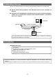
Part Names and Functions Main Body TX/RX LED indicator (Page 5) Lit when transmitting data. 10BASE-T Ethernet terminal (Page 8) To connect to an Ethernet LAN. LINK LED indicator (Page 5) Lit when link is active. RS-232C terminal for controller (Page 9) To connect a commercially available controller or computer. TX/RX 10BASE-T LINK RS-232C(CONTROLLER) Wall mount screw holes (Page 6) To be used for mounting AN-LS1 on a wall. AN-LS1 POWER POWER LED indicator (Page 5) Lit when the power supply is on.
LED Indicators POWER LINK TX/RX Name POWER TX/RX LINK LED Color LED Function Green Off Orange Off Green Off Power is on. Power is off. Network packets are being transmitted or received. No network packet is being transmitted or received. AN-LS1 is connected to the network. Ethernet cable is disconnected. 5 Introduction The LED indicators at the side and on the top of AN-LS1 represent the contents in the following table.
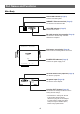
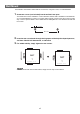
Wall Mount You will find it convenient to mount AN-LS1 on the wall, using two screws, as indicated below. 1 Screw two screws (not included) into the wall 96.5 mm apart. The heads of the screws should be 5-7 mm in diameter, and the shafts should be 3 mm in diameter. (It is recommended to use screws of 12 mm or more in length.) Do not screw the screws in all the way—leave a space of about 4 mm to allow room for sliding AN-LS1’s ears between the wall and the screws. 5-7 mm 96.
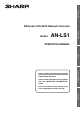
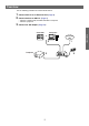
Overview Use the following procedure for connection of AN-LS1. 1 2 Connect AN-LS1 to an Ethernet LAN. (Page 8) 3 Connect the AC adaptor. (Page 10) Connect devices to AN-LS1. (Page 9) • Connect a commercially available controller or computer. • Connect a projector.
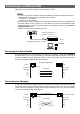
Connecting to an Ethernet LAN Connect AN-LS1 to a hub or a computer using a Category 5 cable. • It is necessary to perform computer setting according to the network environment in advance. • Default IP address and subnet mask of AN-LS1 are as follows: IP address : 192.168.150.2 Subnet mask : 255.255.255.
Connecting Devices Connect a commercially available controller or computer and a projector to AN-LS1. Connecting a Controller or a Computer In the case of controlling a projector via RS-232C as well as via the Ethernet LAN, connect a commercially available controller or computer to the RS-232C (CONTROLLER) terminal. RS-232C (CONTROLLER) or Computer RS-232C serial control cable (commercially available) • For connection procedures for each device, please refer to the operation manual for each device.
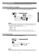
Connecting the AC Adaptor Take the following steps to connect AN-LS1’s AC adaptor. 1 2 Plug the AC adaptor’s DC plug into AN-LS1’s DC IN jack. Plug the AC adaptor into wall outlet. To wall outlet • There is no on/off switch. AN-LS1 turns on as soon as the connected AC adaptor is plugged into a wall outlet. The POWER LED indicator on AN-LS1’s top panel will light green to indicate that it is receiving power. CAUTION • • • • • • The AC adaptor may interfere with reception if used near a radio.
Entering SETUP MENU Connect AN-LS1 to a computer using RS-232C or Telnet, and open the “SETUP MENU” on the computer to carry out various settings for AN-LS1. When Connecting Using RS-232C 1 2 Launch general purpose terminal emulator. Set settings for the RS-232C port of the terminal emulator as follows. Baud Rate Data Length Parity Bit Stop Bit Flow Control : *9600 bps : 8 bit : None : 1 bit : None * This is the default value.
When Connecting Using Telnet 1 2 Click “Start” from the Windows desktop and select “Run”. Enter “telnet 192.168.150.2” in the text box that opens up. (If the IP address of the unit is 192.168.150.2.) 3 4 Click “OK”. “User Name:” is displayed. Input the user name and press the return key. (If a user name has not yet been set, just press the return key.) 5 “Password:” is displayed. Input the password and press the return key. (If a password has not yet been set, just press the return key.
SETUP MENU Description SETUP MENU (Main Menu) SETUP MENU [1]IP Address [2]Subnet Mask [4]User Name [5]Password [6]RS-232C Baud Rate [7]Unit Name [A]Advanced Setup [V]View All Setting [S]Save & Quit [3]Default Gateway [D]Disconnect All [Q]Quit Unchanged setup> [1] IP Address (Factory default setting : 192.168.150.2) IP address settings. (Page 18) [2] Subnet Mask (Factory default setting : 255.255.255.0) Subnet mask settings.
ADVANCED SETUP MENU ******************** ADVANCED SETUP MENU *********************** [1]Auto Logout Time [2]COM Redirect Port [3]Busy Reply [4]Input Hold Time [5]Network Ping Test [6]Accept IP Addr(1) [7]Accept IP Addr(2) [8]Accept IP Addr(3) [9]Accept All IP Addr [0]Port for Search [!]Restore Default Setting [Q]Return to Main Menu advanced> [1] Auto Logout Time (Factory default setting : 5 minutes) Setting of time until automatic disconnection of network connection.
Basic Procedure Enter number or symbol of item to be selected on the “SETUP MENU”. When setting, input the details to be set. Setting is carried out one item at a time, and saved at the end. View Setting Detail List ([V]View All Setting) Displays all setting values.
Set Items (e.g.) When setting IP Address (change from 192.168.150.2 to 192.168.150.3) ▼ The SETUP MENU ———————— S E T U P M E N U —————————— [1]IP Address [2]Subnet Mask [3]Default Gateway [4]User Name [5]Password [6]RS-232C Baud Rate [7]Unit Name [A]Advanced Setup [D]Disconnect All [V]View All Setting [S]Save & Quit [Q]Quit Unchanged setup>1 IP Address : 192.168.150.2 Please Enter : 192.168.150.3 (change) —> 192.168.150.
Quit Save settings and quit. ([S]Save & Quit) Save set values and quit menu. ▼ The SETUP MENU ———————— S E T U P M E N U —————————— [1]IP Address [2]Subnet Mask [3]Default Gateway [4]User Name [5]Password [6]RS-232C Baud Rate [7]Unit Name [A]Advanced Setup [D]Disconnect All [V]View All Setting [S]Save & Quit [Q]Quit Unchanged Enter “s” and press the return key. setup>s All Connection will be disconnect. Continue(y/n)? y Apply New setting...Done. Enter “y” and press the return key.
Setting of Each Item The setting procedure for each item will be explained. For the basic procedure, please refer to page 15. IP Address Setting ([1]IP Address) Setting of IP address. setup>1 IP Address :192.168.150.2 Please Enter :192.168.150.3 (change) —> 192.168.150.3 Enter “1” and press the return key. Enter numerical value to be set and press the return key. Display IP address after change. Subnet Mask Setting ([2]Subnet Mask) Setting subnet mask. Enter “2” and press the return key.
User Name Setting ([4]User Name) Carrying out security protection using user name. Enter “4” and press the return key. setup>4 User Name : Please Enter : an-ls1 (change) —> an-ls1 Enter user name and press the return key. Display set user name. • User name can be up to 8 characters. • In the initial state, user name is not set. Password Setting ([5]Password) Carrying out security protection using password. Enter “5” and press the return key.
Unit Name Setting ([7]Unit Name) It is possible to assign a unit name. When searching using Sharp COM Redirection Software, it is possible to verify a communication destination using the unit name. Enter “7” and press the return key. setup>7 Unit Name : AN-LS1 Please Enter : My An-ls1 (change) —> My An-ls1 Enter unit name. Display set unit name. • Unit name can be up to 12 characters.
The followings are descriptions of the ADVANCED SETUP MENU. Setting Automatic Logout Time (ADVANCED[1]Auto Logout Time) If there is no input after a fixed time, AN-LS1 automatically disconnects network connection using the Auto Logout function. It is possible to set the time until AN-LS1 is automatically disconnected in units of a minute (from 1 to 65535 minutes). advanced>1 Valid range : 0 to 65535 (minute) note: if you enter “0”, auto logout function will be disable.
Busy Reply Setting (ADVANCED[3]Busy Reply) The input terminals of AN-LS1 can be RS-232C (CONTROLLER) and 10BASE-T. Respective input terminals can be connected to separate devices, but in actual if one of the terminals is being used the other terminal cannot be used. When data is being transmitted using one input terminal, it is not possible to use the other input terminal until communication using the first terminal is completed. This setting is for operation of the input terminal that cannot be used.
Carrying out Network Ping Test (ADVANCED[5]Network Ping Test) It is possible to confirm that a network connection between AN-LS1 and a computer etc. is working normally. advanced>5 Ping dest IP addr :192.168.150.1 Please Enter :192.168.150.152 (change) —> 192.168.150.152 32 bytes from 192.168.150.152: icmp_seq = 1, time = 0 ms 32 bytes from 192.168.150.152: icmp_seq = 2, time = 0 ms 32 bytes from 192.168.150.152: icmp_seq = 3, time = 0 ms 32 bytes from 192.168.150.
Setting of Port for Search (ADVANCED[0]Port for Search) Sets the port number used when Sharp COM Redirection Software searches for AN-LS1. advanced>0 Please Enter Port Number for Search from Computer. Valid range : 1025 to 65535 Port for Search : 5006 Please Enter : 5004 (change) —> 5004 Enter “0” and press the return key. Enter numerical value and press the return key. Display set numerical value.
About Sharp COM Redirection Software Using Sharp COM Redirection Software, it is possible to create a “Virtual COM” port. If general application software outputs data to this Virtual COM port, Sharp COM Redirection Software will transfer the data to AN-LS1 which is on a network. With this system, control for a projector conventionally carried out via a COM port can be carried out via an Ethernet LAN without changing control software.
Installation The Sharp COM Redirection software (Virtual COM Driver software) is installed using the installation program provided on the CD-ROM. This manual uses examples to explain the operations for installing the software under Windows XP. 1 Check that this software is suited for your computer. For details, please refer to “About the Sharp COM Redirection Software”. (Page 25) 2 Turn on the power of the computer.
• Please change the destination only when necessary. (In general, it is not necessary to change the destination folder.) • If “Cancel” is clicked, “Exit Setup” dialog will be displayed. • If “Yes” is clicked, the Sharp COM Redirection Software Driver is not installed. If you want to install later, run Sharp COM Redirection Software using “Add or Remove Programs”. • Click “No” to continue the installation. If no dialog box is displayed after waiting a while: (1) Select “Run” from the “Start” menu.
6 Enter a check mark against Virtual COMs to be added to the computer and click “OK”. • It is necessary to add the same number of Virtual COMs as the number of these units used. • If “Cancel” is clicked, the Sharp COM Redirection Software Driver is not installed. If you want to install later, run Sharp COM Redirection Software using “Add or Remove Programs”. When the “Hardware Installation” dialog box is displayed, click “Continue Anyway”. This dialog box may appear a couple of times.
Starting Launch Sharp COM Redirection Software. 1 Launch by double clicking the Sharp COM Redirection Software icon in the Control Panel. • Switch the display of the Control Panel to Classic View. | Open configuration dialog.
Explanation of the Screen ▼ Configuration dialog 1 4 5 6 2 3 8 9 7 1 List display area List display of states of all units recognizing Sharp COM Redirection Software, and allocation states of Virtual COM ports. (Page 32) 2 Search Searches for units, and adds to the list display. (Page 31) 3 Setting Setting of computer data communication port number and search port number. (Page 42) 4 Add Manually adds an unit to list display. (Page 35) 5 Delete Deletes the unit selected within the list display.
Operations Search and Add Searches for units on a network and adds to the list display. 1 Click “Search”. | “Search tool” dialog is displayed, and search for units existing on the network is automatically executed. Using the Software • If you want to re-execute a search, click “Search”.
2 Click the unit to be added to list display. 3 Click “Add to List”. | Added to list display after carrying out communication to each selected unit.
Selecting Virtual COM Port Selecting Virtual COM port used when communicating with AN-LS1. 1 Click the “Virtual COM” column. | The “Virtual COM” column will become a pull-down selectable menu.
2 Click and select the “Virtual COM” number to be used for communication with AN-LS1. 3 Click on an area outside the “Virtual COM” pull down menu. | “Virtual COM” number is changed.
Add (Manual) Adding units to the list display manually in cases such as when units cannot be found, even by searching. 1 Click “Add”. | “Add Unit” dialog will be displayed.
2 Enter IP address and click “OK”. | Unit will be added.
Refresh Changing the list display content to the latest state. 1 Click “Refresh”. | Model Name, Unit Name and Status will be updated to the latest information. Ready : Communication with AN-LS1 is possible. No Response : Communication with AN-LS1 is not possible. Please check connection. (Page 47) Busy : Already connected from another computer. • “Busy” may sometimes be displayed even when a network connection has been disconnected with a normal procedure. (For more details, please refer to page 51.
Delete Deleting an unit from the list display. 1 Click on the unit to be deleted. 2 Click “Delete”.
| A confirmation dialog will be displayed. • If you do not want to delete the unit, click “Cancel”. 3 Click “Yes”. | The unit to be deleted will be removed from the list display.
Password If units with user name/password set appear within the list display, the user name/password for those units must be entered. Enter when communicating with AN-LS1 When communicating with AN-LS1, when a dialog prompting input of user name/password is displayed as shown below, enter the user name and password set at the unit side, enter a check mark in the “Save this password” box, as required, and click “OK”. Inputting in advance It is possible to enter the user name/password in advance.
2 Click “Password”. | A dialog prompting entry of user name/password will be displayed. Enter the user name and password being set to the unit and click “OK”.
Setting Setting of computer data communication port number and search port number. 1 Click “Setting”. | “Setting” dialog will be displayed. 2 Enter “Search Port” number and “Data Port” number and click “OK”. Search Port : Enter port number used for searching AN-LS1. (1025 to 65535) Data Port : Enter port number used for communicating with AN-LS1. (*1025 to 65535) * Values to be entered vary according to the environment setting of the computer. For details, contact your network administrator.
OK/Cancel When defining content of setting or change, click “OK” when closing the “Configuration dialog”. When canceling content of setting or change, click “Cancel” when closing the “Configuration dialog”.
Changing / Removing the Software Be sure to always uninstall the Sharp COM Redirection Software, when reinstalling the Sharp COM Redirection Software or an updated version. 1 2 Quit all running applications. Click the “Start” menu, “Settings”, and then “Control Panel”. (If your operating system is Windows XP, click the “Start” button, and then “Control Panel”.) 3 Click the “Add or Remove Programs” icon. 4 Select “Sharp COM Redirection Software”, and then click “Change/Remove”.
5 Select “Modify”, “Repair” or “Remove”, and then click “Next>” on the “Welcome” dialog box. ■“Modify” For adding or removing Virtual COMs from the computer. The dialog box is displayed and there you can select which Virtual COMs you want to add or remove. ■“Repair” For reinstalling software already in the computer. ■“Remove” For uninstalling (removing) software already installed. Using the Software 6 Follow the instructions on the screen.
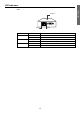
Connecting Pin Assignments RS-232C Terminal: 9-pin D-sub male connector 1 6 5 9 Pin No. 1 2 3 4 5 6 7 8 9 Signal CD RD SD ER SG Name I/O Receive Data Send Data Input Output Signal Ground RS CS CI 10BASE-T terminal: 8-pin RJ-45 connector Pin No. 1 2 3 4 8 Signal TX+ TXRX+ NC 1 46 Pin No.
Troubleshooting The POWER indicator on the top panel does not light green. \ Check if the power plug of the AC adaptor is disconnected from the wall outlet. (Page 10) \ Check that DC IN is connected firmly with the cord from the AC adaptor. (Page 10) Communication cannot be established with AN-LS1 or a projector. When connecting AN-LS1 using serial-connection \ Check that the RS-232C terminal of AN-LS1 and a computer or the serial port of the projector are connected correctly. (Page 9) \ Check that the RS-
Check the network settings for the computer and AN-LS1. \ Check the following network settings for AN-LS1. • IP address \ Check that the IP address for AN-LS1 is not duplicated on the network. • Subnet mask \ When the gateway setting for AN-LS1 is “0.0.0.0” (Not Used), or the gateway setting for ANLS1 and the default gateway setting for the computer are the same: • The subnet masks for AN-LS1 and the computer should be the same.
C:\>ipconfig “RETURN” Usage examples of ipconfig C:\>ipconfig /? displays how to use “ipconfig.exe”. C:\>ipconfig displays the set IP address, subnet mask and default gateway. C:\>ipconfig /all displays all the setting information related to TCP/IP. 3. To return to the Windows screen, enter “exit” and press the “RETURN” key.
\ Check if the “TCP/IP” protocol is operating correctly using the “PING” command. Also, check if an IP address is set. 1. Open a command prompt (MS-DOS Prompt). • In the case of Windows 98 or 98SE: click “START” → “Programs” → “MS-DOS Prompt” in order. • In the case of Windows Me: click “START” → “Programs” → “Accessories” → “MS-DOS Prompt” in order. • In the case of Windows 2000: click “START” → “Programs” → “Accessories” → “Command Prompt” in order.
Sharp COM Redirection Software does not operate. AN-LS1 cannot be found by a search. \ Check the connection. (Refer to “When connecting AN-LS1 to a computer using network (LAN)connection” in Troubleshooting page 47.) \ Check the network settings. (Refer to “Check the network settings for the computer and AN-LS1” in the Troubleshooting page 48.) \ In the case of Windows 2000/XP, is TCP/IP Filtering activated? Invalidate the software or change the settings of the software so that the number of the Port settin
Specifications Main Body Description Input voltage Operating temperature Storage temperature Dimensions (W x H x D) (approx.) Weight (approx.) LEDS Terminal OS Compatibility Ethernet to RS-232C Network Converter DC 6.3 V, 400 mA 41°F to 104°F (5°C to 40°C) -4°F to 158°F (-20°C to 70°C) 3 9/32" x 1 5/32" x 3 7/16" (83 mm x 29 mm x 87 mm) 0.
Index 10BASE-T Ethernet terminal ............................. 8 P Password (AN-LS1) ........................................ 19 Password (Sharp COM Redirection Software) ................ 40 Port for Search ................................................ 24 POWER ............................................................. 5 A Accept All IP Addr ............................................ 23 Accept IP Addr ................................................ 23 Add .........................................
SHARP CORPORATION