
Specifications


Basic Operation
-35
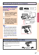
"On-screen Display (Example)
Using
Analog RGB
Using
Component
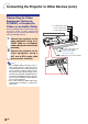
INPUT 2 Mode
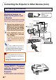
INPUT 3 Mode
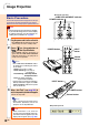
4 Press
and select the input
mode.
• Each press switches in the following
order:
→ INPUT 1 → INPUT 2 → INPUT 3 → INPUT 4
• You can also use the
on the
GyroRemote.
Note
• When no signal is received, “NO SIG-
NAL” will be displayed. When a signal
that the projector is not preset to
receive is input, “NOT REG.” will be
displayed.
• When Auto Search is ON, the input
modes with signals can be selected
(See page 90.)
• When a PC card is inserted, the input
will automatically change to INPUT 4.
• You can select the input mode directly
by using the Button Assign function
on the GyroRemote (See page 41.)
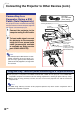
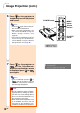
About the INPUT Modes
Used for projecting images
from equipment that sends
RGB signals or Component
signals connected to the DVI-
DIGITAL/ANALOG input port.
Used for projecting images
from equipment connected to
the S-VIDEO input terminal.
Used for projecting images
from equipment connected to
the VIDEO input terminal.
When projecting from a wire-
less LAN PC card or a
memory card.
INPUT 1
(RGB/
Component)
INPUT 2
(S-Video)
INPUT 3
(V
ideo
)
INPUT 4
(PC Card)
INPUT 1 Mode
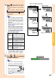
5 Press
or
on the projector
to adjust the volume.
Note
• Pressing “+” will raise the volume.
Pressing “–” will lower the volume.
• On the GyroRemote, the volume can
be adjusted by pressing
.
• When a PC card is installed,
,
on the projector or
on the
GyroRemote operate as cursor
buttons (\, |) when the OSD menu
is active.
Using
DVI digital
Using S-Video
Using Video
INPUT 4 Mode
Memory card installed
•
Transmission will be stopped if the input
is switched when a wireless LAN PC
card is installed in INPUT 4 and the
projector is connected to a computer.