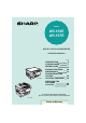
MODEL AR-153E AR-157E DIGITAL LASER COPIER/PRINTER OPERATION MANUAL Page INTRODUCTION LOADING PAPER MAKING COPIES SPECIAL FUNCTIONS MAINTENANCE AR-153E TROUBLESHOOTING THE UNIT OPTIONAL EQUIPMENT INSTALLING THE SOFTWARE APPENDIX 4 7 12 20 25 30 38 40 69 To navigate through this document, please use the arrow keys on your keyboard AR-157E Return to Directory
FOR YOUR RECORDS ... To protect against loss theft, record and retain for reference the copier's serial number located on the back of the unit.
CAUTIONS Caution label on the unit The label ( ) in the fusing area of the unit indicates the following: : Caution, risk of danger : Caution, hot surface Cautions on using Follow the cautions below when using this unit. Warning: • The fusing area is hot. Exercise care in this area when removing misfed paper. • Do not look directly at the light source. Doing so may damage your eyes. • Do not switch the unit rapidly on and off. After turning the unit off, wait 10 to 15 seconds before turning it back on.
Cautions on handling Be careful in handling the unit as follows to maintain the performance of this unit. Do not drop the unit, subject it to shock or strike it against any object. Store spare toner cartridges in a cool dry place without removing from the package before use. • If they are exposed to direct sunlight or excessive heat, poor copies may result. Do not touch the photoconductive drum (green portion). • Scratches or smudges on the drum will cause dirty copies.
CONTENTS 1 INTRODUCTION USING THE MANUAL ................... 4 PART NAMES ............................... 5 OPERATION PANEL..................... 6 2 LOADING PAPER PAPER........................................... 7 LOADING THE PAPER TRAY....... 8 BYPASS FEED (including special paper).............. 10 3 MAKING COPIES COPY FLOW ............................... 12 POWER ON................................. 13 ORIGINAL PLACEMENT............. 14 SET THE COPY QUANTITY .......
1 INTRODUCTION This chapter provides basic information for using the unit. USING THE MANUAL The operation manual contains explanations of how to operate the unit, important considerations, and maintenance procedures. To get the most out of the unit, please read the operation manual. Please keep the operation manuals in a suitable location that will allow for convenient future reference. Conventions used in the manual This operation manual explains the operation of the AR-153E and AR-157E models.
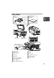
PART NAMES RSPF (AR-157E) Original cover (AR-153E) Original guide 1 Feeding roller cover Original exit area Original feeder tray 1 2 8 9 5 6 7 3 10 11 12 4 Paper tray 2 Multi-bypass tray Photoconductive drum 5 Toner cartridge 13 14 3 15 1 2 3 4 5 6 7 8 9 Original table Operation panel Front cover Paper tray Side cover Side cover open button Bypass paper guides Paper output tray Paper output tray extension 10 11 12 13 14 15 Power switch Handle Power cord Fusing unit release lever Transfe
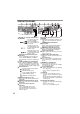
OPERATION PANEL 1 Original to copy key and indicators (AR-157E) Two-sided copies from one-sided originals. Turn on Long Edge or Turn on Short Edge can be selected. Two-sided copies from two-sided originals. (Can be selected only when the RSPF is used.) Single-sided copies from two-sided originals. (Can be selected only when the RSPF is used.) 2 Exposure mode selector key and indicators Use to sequentially select the exposure modes: AUTO, MANUAL or PHOTO. Selected mode is shown by a lit indicator. (p.
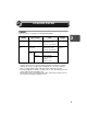
2 LOADING PAPER Follow the steps below to load paper into the tray. PAPER For best results, use only paper recommended by SHARP. Type of paper feeding Type of media Size Weight Paper tray Standard paper Letter (8-1/2" x 11") Legal (8-1/2" x 14") Invoice (5-1/2" x 8-1/2") 15 lbs. to 21lbs. Multi-bypass tray Standard paper and thick paper Letter (8-1/2" x 11") Legal (8-1/2" x 14") Invoice (5-1/2" x 8-1/2") 14 lbs. to 34.5 lbs.
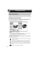
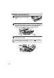
LOADING THE PAPER TRAY 1 Raise the handle of the paper tray and pull the paper tray out until it stops. 2 Adjust the paper guides on the paper tray to the copy paper width and length. Squeeze the lever of paper guide A and slide the guide to match with the width of the paper. Move paper guide B to the appropriate slot as marked on the tray. Paper guide B 3 Paper guide A Fan the paper and insert it into the tray. Make sure the edges go under the corner hooks.
4 Gently push the paper tray back into the unit. • After loading paper, to cancel the blinking without restarting copying, press the clear ( ) key. The in the display will go out and the start ( ) indicator will light up. • Be sure that paper is free of rips, dust, wrinkles, and curled or bent edges. • Make sure all the paper in the stack is the same size and type.
BYPASS FEED (including special paper) The multi-bypass tray can be used to feed standard paper, transparency film, labels, envelopes and other special purpose paper. Paper measuring from 3-1/2" x 5-1/2" to 8-1/2" x 14" and in the weight range of 14 lbs. to 34.5 lbs. can be used in this tray. (For paper weighing from 28 lbs. to 34.5 lbs., 8-1/2" x 11" is the maximum size.) • The multi-bypass tray can hold maximum of 50 sheets of paper. (Capacity will vary depending on the type of paper loaded.
• Paper must be fed narrow side into the feed slot. • Special papers such as transparency film and labels must be fed one sheet at a time through the multi-bypass tray. • When copying onto transparency film, remove each copy promptly. Do not let copies stack up. 3 Press the tray select ( ) key to select the multi-bypass tray. Note for loading envelopes 2 • Envelopes must be fed narrow side into the feed slot one at a time.
3 MAKING COPIES This chapter explains basic and other copying functions. The unit is equipped with a one-page memory buffer. This memory allows the unit to scan an original once only and make up to 99 copies. This feature improves workflow, reduces operation noise from the copier, and provides higher reliability by reducing wear and tear on the scanning mechanism. If the unit does not function properly during use, or if a function cannot be used, see "TROUBLESHOOTING THE UNIT" (p.30).
POWER ON Turn the power switch on the left side of the unit to the "ON" position. The start ( indicator will light up. ) • The unit will enter a power save mode once the set time has elapsed without any unit operation. The settings of the power save modes can be modified. See "USER PROGRAMS" (p.23). • The unit will return to the initial settings a preset amount of time after the end of copy or scanner job. The preset amount of time (auto clear time) can be changed. See "USER PROGRAMS" (p.23).
Power off methods If not used for a certain period of time, the unit will automatically enter auto power shut-off mode (p.22) in order to minimize power consumption. In cases where the machine will not be used for a long time, turn off the power switch and remove the power cord from the outlet. ORIGINAL PLACEMENT Using the original table • The original table can read up to 8-1/2" x 14" original. • Image loss 5/32" can occur at the leading and trailing edges of the copies.
EQR[ HO ࡍࠫ 㧞㧜㧜㧞ᐕ㧢㧝㧜ᣣᦐޓᣣޓඦ೨㧝㧝ᤨ㧡㧟ಽ Using the RSPF/SPF The RSPF/SPF is designed to hold up to 30 originals measuring from 5-1/2" x 8-1/2" to 8-1/2" x 14" and weighting from 14 lbs. to 23.9 lbs. • Before feeding originals in the original feeder tray, be sure to remove any staples or paper clips from them. • Before placing curled or wavy originals into the original feeder tray, be sure to flatten them. If not, original misfeeds may result.
SET THE COPY QUANTITY Set the number of copies using the two copy quantity ( from the original table or copying from RSPF/SPF. , ) keys when copying • Press the clear ( ) key to clear an entry if a mistake is made. • A single copy can be made with the initial setting, i.e., when "0" is displayed. • Press the right copy quantity key to set the unit digit from 0 to 9. This key will not change the tens digit. • Press the left copy quantity key to set the tens digit from 1 to 9.
Automatic exposure adjustment This automatic exposure level will remain in effect until you change it again by this procedure. The automatic exposure level can be adjusted to suit your copying needs. This level is set for copying from the original table and copying from the RSPF/SPF respectively. 1 When adjusting the automatic exposure level for copying from the RSPF/SPF, place an original in the original feeder tray and make sure that the RSPF/SPF ( ) indicator lights up.
REDUCTION/ENLARGEMENT/ZOOM Three preset reduction ratios and two enlargement ratios can be selected. The zoom function enables copy ratio selection from 25% to 400% in 1% increments. 1 Set the original and check the paper size. 2 Use the copy ratio selector key and/or ZOOM ( select the desired copy ratio. , ) keys to • To verify a zoom setting without changing the zoom ratio, press and hold down the copy ratio display (%) key.
SELECTING THE TRAY • Paper sizes that can be used in the duplex copy mode are letter, legal, and invoice. When copying from the original table in the duplex copy mode, only letter size paper can be used. (AR-157E) • The multi-bypass tray cannot be used in the duplex copy mode. Press the tray select ( ) key. Each time you press the tray select ( ) key, the location indicated by the paper feed location indicator changes in the following order: paper tray 1, paper tray 2, multibypass tray.
4 SPECIAL FUNCTIONS This chapter describes the special functions of this unit. Use these functions as needed. ABOUT THE SPECIAL FUNCTIONS OF AR-157E Two sided copying When copying from the RSPF, two-side originals can be copied automatically without having to manually turn them over. Automatic two-sided copying can also be performed without using the RSPF. When copying from one-sided originals to twosided copies, copying orientation can be selected between Turn on Long Edge and Turn on Short Edge.
Making two-sided copies 1 Place the original(s) on the original table or in the RSPF. (see "ORIGINAL PLACEMENT" (p.14). 2 Select two-sided copy mode. A: When copying in a one-sided to two-sided mode: Use the original to copy key to select the desired one-sided to two-sided copying mode (Turn on Long Edge or Turn on Short Edge). See the illustrations on page 20. B: When copying in the two-sided to two-sided mode: Use the original to copy key to select the two-sided to two-sided copying mode.
DESCRIPTION OF SPECIAL FUNCTIONS Toner save mode (page 22) Reduces toner consumption by approximately 10%. Power save modes (page 23) The unit has two power save modes of operation: preheat mode and auto power shut-off mode. Preheat mode When the unit enters the preheat mode, the power save ( ) indicator will light up and other indicators will remain on or off as before. In this condition, the fuser in the unit is maintained at a lower heat level, thereby saving power.
2 Press and hold down the exposure mode selector key for approximately 5 seconds. The MANUAL ( ) indicator will go out and the PHOTO ( ) indicator will begin to blink. The light and dark indicator marked "5" will light up, indicating the standard toner mode is active. 3 To enter the toner save mode, press the light ( ) key. The light and dark indicator marked "1" will light up, indicating the toner save mode is selected. 4 Press the exposure mode selector key.
Program No. Mode Parameters 1 Auto clear time 0 *3 OFF, 1 10sec., 2 30sec. 60sec., 4 90sec., 5 120sec. 2 Preheat mode *0 3 Auto power shut- off timer 0 3 2min., *1 30min., 4 4 Stream feeding mode 0 OFF, *1 ON 5 Auto power shut- off mode 0 OFF, *1 ON 6 Resolution of AUTO & MANUAL mode *0 30sec., 1 300dpi, 1 60sec., 2 90sec. 5min., 2 15min., 60 min., 5 120min. 600dpi * Factory default settings are indicated with an asterisk (*). Program No.
5 MAINTENANCE This chapter describes how to replace the toner cartridge and how to clean the unit. Be sure to use only genuine SHARP parts and supplies. For best copying results, be sure to use only SHARP Genuine Supplies which are designed, engineered, and tested to maximize the life and performance of SHARP copiers. Look for the Genuine Supplies label on the toner package.
3 Gently pull the toner cartridge out while pressing the lock release lever. Toner cartridge lock release lever • After removing the toner cartridge, do not shake it or tap on it. Doing so may cause toner to leak from the cartridge. Put the old cartridge immediately in the bag contained in the box of the new cartridge. • Dispose of the old toner cartridge in accordance with local regulations. 4 Remove the toner cartridge from the bag.
6 Close the front cover and then the side cover by pressing the round projections near the side cover open button. The indicator will go out and the start ( ) indicator will light up. When closing the covers, be sure to close the front cover securely and then close the side cover. If the covers are closed in the wrong order, the covers may be damaged.
CLEANING THE UNIT Proper care is essential in order to get clean, sharp copies. Be sure to take a few minutes to regularly clean the unit. • Before cleaning, be sure to turn the power switch off and remove the power cord from the outlet. • Do not use thinner, benzene or other volatile cleaning agents. Doing so may cause deformation, discoloration, deterioration or malfunction. Cabinet Wipe the cabinet with a soft, clean cloth.
Transfer charger If copies start becoming streaky or blotchy, the transfer charger may be dirty. Clean the charger using the following procedure. 1 Turn the power switch off. (p.14) 2 Ensure that the multi-bypass tray is open and then open the side cover while pressing the side cover open button. 3 Take the charger cleaner out by holding the tab. Set the charger cleaner onto the right end of the transfer charger, gently slide the cleaner to the left end, and then remove it.
6 TROUBLESHOOTING THE UNIT This chapter describes misfeed removal and troubleshooting. TROUBLESHOOTING If any problem occurs, check the list below before contacting the SHARP service center. Problem Unit does not operate. Blank copies Copies are too dark or too light. Dust, dirt, smudges appear on copies.
STATUS INDICATORS When the following indicators light up or blink on the operation panel or the following alphanumeric codes appear in the display, solve the problem immediately referring to both the table below and the relevant page. Be sure to use only genuine SHARP parts and supplies. Indication Developer replacement required indicator Toner cartridge replacement required indicator Misfeed indicator Maintenance indicator Cause and remedy Steadily Developer is required.
MISFEED REMOVAL When the misfeed ( ) indicator blinks or blinks in the display, the unit will stop because of a misfeed. If a misfeed occurs when using the RSPF/SPF, a number may appear in the display after a minus sign. This indicates the number of the originals that must be returned to the original feeder tray after a misfeed. Return the required number of originals. Then this number will disappear when copying is resumed or the clear ( ) key is pressed.
A: Misfeed in the paper feed area 1 Gently remove the misfed paper from the paper feed area as shown in the illustration. When the misfeed ( ) indicator blinks and the misfed paper is not seen from the paper feed area, pull out the paper tray and remove the misfed paper. If the paper cannot be removed, proceed to "B: Misfeed in the fusing area". The fusing unit is hot. Do not touch the fusing unit when removing misfed paper. Doing so may cause a burn or other injury.
2 Gently remove the misfed paper from under the fusing unit as shown in the illustration. If the paper cannot be removed, proceed to "C: Misfeed in the transport area". The fusing unit is hot. Do not touch the fusing unit when removing misfed paper. Doing so may cause a burn or other injury. • Do not touch the photoconductive drum (green portion) when removing the misfed paper. Doing so may cause smudges on copies. • Do not remove the misfed paper from above the fusing unit.
4 Raise the fusing unit release lever, close the front cover and then close the side cover by pressing the round projections near the side cover open button. The misfeed ( ) indicator will go out and the start ( ) indicator will light up. When closing the covers, be sure to close the front cover securely and then close the side cover. If the covers are closed in the wrong order, the covers may be damaged.
(B) Open the RSPF/SPF and rotate the roller rotating knob to remove the misfed original from the exit area. If the misfed original cannot be easily removed, proceed to (C). Roller rotating knob (AR-157E) With the RSPF, pull out the reversing tray to remove the misfed original. With the RSPF, after removing the misfed original from the exit area, be sure to insert the reversing tray into the exit area until it locks in place.
DEVELOPER REQUIRED When the developer replacement required ( ) indicator lights up, the developer should be replaced. DEVELOPER REPLACEMENT SHOULD ONLY BE DONE BY AN AUTORIZED SHARP SERVICE TECHNICIAN. Contact your service center as soon as possible. MAINTENANCE REQUIRED When maintenance ( ) indicator lights up, service by an authorized SHARP service technician is required. Contact your service center as soon as possible.
7 OPTIONAL EQUIPMENT SYSTEM CONFIGURATION A number of options are available for the unit which allow you to configure a system to meet your particular needs. The options include the following. Printer/Scanner Expansion Kit (AR-PG2) Single pass feeder (AR-SP5) AR-157E 250-sheet paper feed unit (AR-D16) AR-153E PRINTER/SCANNER EXPANSION KIT (AR-PG2) A printer function and scanner function can be added to the unit by installing the ARPG2.
250-SHEET PAPER FEED UNIT (AR-D16) The paper feed unit provide the convenience of increased paper capacity for the unit and a greater choice of paper size readily available for copying. The procedures for loading paper in the paper tray of paper feed unit, changing the paper size, and selecting the paper tray are same as for the paper tray in the unit. See "LOADING THE PAPER TRAY" (p.8) and "SELECTING THE TRAY" (p.19).
8 INSTALLING THE SOFTWARE The procedure for installing the software for the optional AR-PG2 Printer/Scanner Expansion Kit and the operation of the printer/scanner is explained here. Information on how to use the online manual is also provided. Illustrations of driver screens and other computer screens show the screens that appear in Windows XP Home Edition. Some of the names that appear in these illustrations may differ slightly from the screens that appear in other operating systems.
HARDWARE AND SOFTWARE REQUIREMENTS Check the following hardware and software requirements in order to install the software. Computer type IBM PC/AT or compatible computer equipped with a USB1.1*1 or bi-directional parallel interface (IEEE 1284) Operating system*2 Windows 95, Windows 98, Windows Me, Windows NT Workstation 4.
Flow of installation Refer to the following table and then begin installation. Operating system Windows XP Windows 98 Interface Reference pages for how to install USB/ Parallel USB Installing onto Windows XP (USB/parallel interface) (p.43) Installing onto Windows 98/Me/2000 (USB interface) (p.47) Installing onto Windows 95/98/Me/NT4.0/2000 (Parallel interface) (p.50) Installing onto Windows 98/Me/2000 (USB interface) (p.47) Installing onto Windows 95/98/Me/NT4.0/2000 (Parallel interface) (p.
INSTALLING THE SOFTWARE The following term is used in this section. MFP Means the unit as a printer and scanner. • For this description, it is assumed that the mouse is configured for right hand operation. • To print or scan, the MFP must be in the online state. • The scanner feature only works when using a USB interface cable. • If any error message appears, solve the problem following the instructions on the screen. After your problem is solved, the installing procedure will be continued.
• If you are using the parallel interface connection, do not select the Button Manager checkbox because this feature is not supported with the parallel interface. • If the following screen appears, click the "OK" button. Review the contents in "BEFORE INSTALLATION" (p.41), and then select only appropriate the software packages to be installed. 5 Review the software packages to be installed on the screen, and then click the "Start" button.
7 Begin installation of the Button Manager (This step will start if it was selected in step 4). 1 2 3 4 5 8 Begin installation of the Sharpdesk (This step will start if it was selected in step 4). 1 2 3 4 5 9 After confirming the message in the "Welcome" window, click the "Next" button. Read the message in the "Please read the following information." window, and then click the "Next" button.
10 Connect the USB interface cable or parallel interface cable. (p.67) Windows will detect the MFP and the Plug and Play screen will appear. If you are using Windows XP with the parallel interface, go to step 12. 11 Begin installation of the scanner driver. 1 2 3 12 "SHARP AR-xxxx" (where xxxx is the model name of your MFP) will appear in the "Found New Hardware Wizard" dialog box. Select "Install the software automatically (Recommended)" and click the "Next" button.
Installing onto Windows 98/Me/2000 (USB interface) Before starting the installation, make sure the USB interface cable is not connected to the MFP. 1 Insert the supplied CD-ROM into your CD-ROM drive. 2 Double-click "My Computer" ( CD-ROM ( ) icon. ), and then double-click the When any of "Hardware Found", or "Found New Hardware Wizard" messages appear during the software installation, be sure to click the "Cancel" button. 3 Double-click the "setup" ( ) icon.
6 Copying files for MFP driver installation. 1 2 3 4 5 7 When the "The MFP driver installation is complete." dialog box appears, click the "OK" button. The Button Manager installer will start. Begin installation of the Button Manager (This step will start if it was selected in step 4). 1 2 3 4 5 48 After confirming the message in the "Welcome" window, click the "Next" button. A dialog box appears asking you to verify that the interface cable is not connected to the MFP.
8 Begin installation of the Sharpdesk (This step will start if it was selected in step 4). 4 After confirming the message in the "Welcome to Sharpdesk installation" window, click the "Next" button. Read the message in the "Information" window, and then click the "Next" button. When the "Choose Destination Location" window appears, click the "Next" button. When the "Select Program Folder" window appears, click the "Next" button. The setup program will start to copy the files.
Installing onto Windows 95/98/Me/NT4.0/2000 (Parallel interface) Before starting the installation, make sure the USB or parallel interface cable is not connected to the MFP. 1 Insert the supplied CD-ROM into your CD-ROM drive. 2 Double-click "My Computer" ( CD-ROM ( ) icon. ), and then double-click the When any of "Hardware Found", or "Found New Hardware Wizard" messages appear during the software installation, be sure to click the "Cancel" button. 3 Double-click the "setup" ( ) icon.
7 Copying files for MFP driver installation and parallel interface setup (This step will start if it was selected in step 4). 1 2 3 4 After confirming the message in the "Welcome" window, click the "Next" button. A dialog box appears asking you to verify that the USB or parallel interface cable is not connected to the MFP. Make sure that the interface cable is not connected and click the "Next" button.
8 Begin installation of the Sharpdesk (This step will start if it was selected in step 4). 4 After confirming the message in the "Welcome to Sharpdesk installation" window, click the "Next" button. Read the message in the "Information" window, and then click the "Next" button. When the "Choose Destination Location" window appears, click the "Next" button. When the "Select Program Folder" window appears, click the "Next" button. The setup program will start to copy the files.
INDICATORS ON THE OPERATION PANEL The ONLINE indicator and the start ( scanner. ) indicator indicate the state of the printer or SCANNER indicator ONLINE indicator Start indicator Power save indicator Start indicator On: Indicates the unit is ready for copying or scanning is being performed. Blinking: The indicator blinks in the following situations: • When a print job is interrupted. • During initialization of the unit. (the cover has been opened and closed or the power turned off and on.
USING THE PRINTER MODE For problems with the printer function, see the online manual or the help file for the driver. Opening the printer driver from the start menu Open the printer driver setup screen by the method shown below. 1 Click the "start" button. 2 Click "Control Panel", select "Printers and Other Hardware", and then click "Printers and Faxes". On Windows 95/98/Me/NT4.0/2000, select "Settings" and click "Printers".
4 Specify the print settings including the number of copies, media type, and print quality, and then click the "Print" button to start printing. On Windows 95/98/Me/NT 4.0, click the "OK" button to start printing. For details on print settings, see the online manual or the help file for the printer driver. • If copying is being performed when printing is started, copying will continue.
USING THE SCANNER MODE For problems with the scanner function, see the online manual or the help file for the driver. Using the Button Manager Setting up the Button Manager The scanner driver for this unit includes an STI (Still image) driver and WIA (Windows Image Acquisition) driver. You can install software that supports the STI driver and WIA driver to enable scanning using only the operation panel of the unit. The Button Manager accessory software supports the STI driver and WIA driver.
Windows 98/Me/2000 To scan directly into an application using the Button Manager on Windows 98, Windows Me and Windows 2000. Set the Event Manager properties to send only to Button Manager as shown below. 1 Click the "Start" button, select "Control Panel" from "Settings", and open "Scanners and Cameras" in start menu. In Windows Me, it occasionally happens that the "Scanners and Cameras" icon does not appear immediately after installation of the MFP driver is completed.
Scan Button Destination Setting Dialog Box After you have completed the Button Manager settings in Windows, configure the scan settings in Button Manager. To configure the scan settings in Button Manager, right click the ( ) icon in the Taskbar and select "Setting" from the menu that appears. For details on configuring the scan settings in Button Manager, see the online manual or the help file.
The settings for the Windows Event Manager for the SHARP AR-xxxx (where xxxx is the model name of your unit) device allow the user to take advantage of the Sharp Button Manager to take control of events from Windows and send scanned images to any of six different applications according to the Button Manager setting.
Using the SCANNER key to begin scanning • Scanning is not possible during a copy job. • If the unit is used to begin a scan job during a print job, the scan job will be stored and scanning will begin when the print job is completed. • When scanning an original that has been placed in the RSPF/SPF, only one original can be placed unless you are using Sharpdesk. 1 Press the SCANNER ( ) key. The unit enters scan mode. 2 Place the original you wish to scan on the original table/RSPF/ SPF.
4 Press the start ( ) key. The selected application launches and scanning begins. If the following screen appears, select Button Manager and click "OK". Button Manager starts and the application associated with Button Manager starts. If you want only Button Manager to start in this case, set up Button Manager for use in Windows as explained in "Setting up the Button Manager" (p.56). Opening the scanner driver and scanning from your computer Follow the steps below to open the scanner driver setup screen.
3 Select "SHARP Personal MFP series", and click the "Select" button. Click here If you use more than one scanning device, select the scanner you want to use through the application. The method for accessing the "Select Scanner" option, depends upon the application. For more information, see the online manual or the help file of your application. 4 Select "Acquire Image" from the "File" menu, or click the "Acquire" button ( ).
Scanning with the "Scanner and Camera Wizard" in Windows XP Windows XP includes as a standard feature an image scanning function. The procedure for scanning with the "Scanner and Camera Wizard" is explained here. To cancel scanning, click the "Cancel" button in the screen that is displayed. 1 Place the original you wish to scan on the original table/RSPF/ SPF. For the procedure for placing the original, see "ORIGINAL PLACEMENT" (p.14).
HOW TO USE THE ONLINE MANUAL The online manual provides detailed instructions for operating the unit as the printer or scanner and a list of methods for dealing with printing or scanner problems. To access the online manual, your computer must have Acrobat Reader 5.0 or a later version. If it is not installed, refer to "Installing Acrobat Reader" (Next page). Contents of the online manual The contents of the online manual are as follows.
5 Click the to read the online manual. To close the online manual, click the ( the window. ) button located at the top-right of • The online manual can be printed out using Acrobat Reader. SHARP recommends printing out the sections which you refer to regularly. • Refer to "Help" of Acrobat Reader for more details on the operation and function of Acrobat Reader. Installing Acrobat Reader 1 Turn on your computer. 2 Insert the CD-ROM into the CD-ROM drive.
USING OTHER INSTALLED DRIVERS If you use another GDI printer or a Windows Printing System printer, interference between printers may occur and printing may not be performed properly. To use another GDI printer or a Windows Printing System printer, you must change the port setting of the printer driver using the following procedure.
CONNECTING THE INTERFACE CABLE This unit includes both USB and parallel interface connectors. Interface cables for connecting the unit to your computer are not included with this unit. Please purchase the appropriate cable for your computer. Interface cable Parallel interface cable IEEE 1284-Shielded type bi-directional parallel interface cable (6 feet Max.) USB interface cable Shielded twisted pair cable, high-speed transmission equivalent (6 feet Max.
Connecting the parallel interface cable 68 1 Obtain an IEEE1284 shielded parallel interface cable. 2 Ensure that your computer and unit are turned off. 3 Insert the cable into the parallel interface connector located on the rear of the unit, and fasten with clasps. 4 Insert the other end of the cable into the interface connector of your computer.
9 APPENDIX SPECIFICATIONS Model AR-153E AR-157E Type Digital laser copier/printer, desk-top type Copy system Dry, electrostatic transfer Originals Sheets, bound documents Paper tray 250 sheets Multi-bypass tray 50 sheets Paper output tray 100 sheets RSPF Original sizes Original feed — Original table/ RSPF Max. 8-1/2" x 14" Original table 1 sheet RSPF — RSPF Up to 30 sheets Copy size 3-1/2" x 5-1/2" to 8-1/2" x 14"*1 Image loss Max. 5/32" *2 Max. 11/64" *3 Max.
Model Width AR-153E 20.4" Unit dimensions Depth 19.4" 19.4" Height 11.6" 18.3" Operating conditions Temperature: 50°F to 86°F Humidity: 20% to 85% Noise level Sound Power Level LwA (1B=10dB) Copying: 6.0 [B], Standby: 3.7 [B] Sound Pressure Level LpA (bystander positions) Copying: 46 [dB (A)], Standby: 23 [dB (A)] Noise emission measurement in accordance with ISO 7779. Emission concentration (measurement according to RAL-UZ 62) Ozone: less than 0.02 mg/m3 Dust: less than 0.
Optional equipment Printer/Scanner Expansion Kit (AR-PG2) Printing system Dry, electrostatic transfer Printing size 3-1/2" x 5-1/2" to 8-1/2" x 14" *1 Print speed Max. 12 pages/min. (Letter or A4) Continuous printing Max. 99 pages subtractive counter First-print time (Approximately) 9.6 seconds (Paper: A4) *2 Resolution Printer 600 dpi Scanner 600 x 1200 dpi Emulation SHARP GDI Page orientation Portrait or landscape Interface port USB interface (USB1.
INDEX 2 D 250-Sheet paper feed unit ................. 39 Dark key ........................................ 6, 16 Developer replacement required indicator................................... 6, 31, 37 Developer required............................ 37 Display................................................. 6 Displaying total number of copies ..... 24 A Acrobat Reader ................................. 65 Alarm indicator - Developer replacement required indicator..............................
M Maintenance indicator ............. 6, 31, 37 Making copies ................................... 12 MFP driver - Print Status Window ..................... 40 - Printer driver................................. 40 - Scanner driver .............................. 40 Misfeed indicator ..................... 6, 31, 32 Misfeed removal - Fusing area .................................. 33 - Lower paper feed area ................. 35 - Paper feed area............................ 33 - RSPF/SPF...........................
Z ZOOM indicator ............................. 6, 18 ZOOM key ..................................... 6, 18 INDEX BY PURPOSE Cleaning the unit - Cabinet ......................................... 28 - Original cover ............................... 28 - Original table ................................ 28 - RSPF/SPF.................................... 28 - Transfer changer .......................... 29 Connecting the interface cable - Parallel interface cable ................. 68 - USB interface cable...........
SOFTWARE LICENSE PLEASE READ THIS LICENSE CAREFULLY BEFORE USING THE SOFTWARE. BY USING THE SOFTWARE, YOU ARE AGREEING TO BE BOUND BY THE TERMS OF THIS LICENSE. 1. License. The application, demonstration, system and other software accompanying this License, whether on disk, in read only memory, or on any other media (the "Software") and related documentation are licensed to you by SHARP.
6. Limited Warranty on Media. SHARP warrants the disks on which the Software is recorded to be free from defects in materials and workmanship under normal use for a period of ninety (90) days from the date of purchase as evidenced by a copy of the receipt. The entire liability of SHARP and/or its Licensors and your exclusive remedy will be replacement of the disk which fails to meet the limited warranty provided by this Clause 6.
Date Issued:Nov. 1, 2000 MATERIAL SAFETY DATA SHEET MSDS No. F-01001 Section 1. Product Identification Product: AR-152NT/T/FT/ST (Black Toner) Section 2. Supplier’s Name and Address Sharp Corporation 22-22 Nagaike-cho, Abeno-ku, Osaka, Japan Local suppliers are listed below. Please contact the nearest supplier for additional information. (Country) U.S.A. Canada United Kingdom Section 3. Ingredients Ingredients Styrene-Acrylate copolymer Carbon black Iron oxide Metal Complex dye Section 4.
Section 6. Physical Chemical Characteristics Boiling / Melting Point: Vapor Pressure: Vapor Density: Evaporation Rate: Appearance: Odor: Section 7. Not applicable Not applicable Not applicable Not applicable Fine powder Odorless Not applicable >350¡C (LEL); Not applicable (UEL); Not applicable CO2, dry chemical, foam or water None This material has no unusual fire or explosion hazards.
Date Issued :Nov. 1, 2000 MATERIAL SAFETY DATA SHEET MSDS No. F-31001 Section 1. Product Identification Product AR-152ND/DV/SD (Black Developer) Section 2. Supplier’s Name and Address Sharp Corporation 22-22 Nagaike-cho, Abeno-ku, Osaka, Japan Local suppliers are listed below. Please contact the nearest supplier for additional information. (Country) U.S.A. Canada United Kingdom Section 3. Ingredients Ingredients Iron powder Styrene-Acrylate copolymer Carbon black Section 4.
Section 6. Physical Chemical Characteristics Boiling / Melting Point: Vapor Pressure: Vapor Density: Evaporation Rate: Appearance: Odor: Section 7. Not applicable Not applicable Not applicable Not applicable Fine powder Odorless Not applicable >350¡C (LEL); Not applicable (UEL); Not applicable CO2, dry chemical, foam or water None This material has no unusual fire or explosion hazards.
♠♠♠♠♠♠♠♠♠♠♠♠♠♠♠♠♠♠♠♠♠♠♠♠♠♠♠♠♠♠♠♠♠♠♠♠♠♠♠♠♠♠♠♠♠♠ For users in the USA This device complies with Part 15 of the FCC rules. Operation is subject to the following two conditions: (1) This device may not cause harmful interference, and (2) this device must accept any interference received, including interference that may cause undesired operation.
SHARP ELECTRONICS CORPORATION Sharp Plaza, Mahwah, New Jersey 07430-2135. www.sharp-usa.