SERVICE MANUAL COLOR LED PRINTER MODEL AR-C265P CONTENTS CHAPTER 1 CONFIGURATION ......................................... 1-1 CHAPTER 2 EXPLANATION OF OPERATION.................. 2-1 CHAPTER 3 INSTALLATION ............................................. 3-1 CHAPTER 4 REPLACEMENT OF PARTS ......................... 4-1 CHAPTER 5 MAINTENANCE MENUS ............................... 5-1 CHAPTER 6 PERIODICAL MAINTENANCE ...................... 6-1 CHAPTER 7 TROUBLESHOOTING PROCEDURES ........
INTRODUCTION This manual explains the maintenance methods for the AR-C265P. The manual has been prepared for use by the maintenance personnel. For operating methods of the AR-C265P, refer to the corresponding user's manual. Note! • The contents of this manual are subject to changes without prior notice. • Despite that exhaustive efforts were made in preparing the manual to make it accurate, it still may contain errors.
CONTENTS CHAPTER 1 I. II. III. IV. V. CONFIGURATION SYSTEM CONFIGURATION .............1-1 PRINTER CONFIGURATION ............1-2 COMPOSITION OF OPTIONAL ITEMS ................................................1-3 SPECIFICATIONS .............................1-4 INTERFACE SPECIFICATIONS........1-8 A. B. C. Parallel interface specifications (N/A) .............................................1-8 USB interface specifications.........1-8 Network interface specifications ...
CHAPTER 4 I. A. II. A. B. C. D. E. F. G. H. I. J. K. L. REPLACEMENT OF PARTS PRECAUTIONS ON THE REPLACEMENT OF PARTS............. 4-1 Maintenance tools ........................ 4-2 PART REPLACEMENT METHODS......................................... 4-3 Left side cover.............................. 4-3 Right side cover ........................... 4-4 Face-up tray ................................. 4-5 Rear cover.................................... 4-6 LED assy/LED assy springs ........ 4-7 Control PCB .......
CHAPTER 7 I. II. III. IV. TROUBLESHOOTING PROCEDURES PRECAUTIONS PRIOR TO REPAIR..............................................7-1 ITEMS TO BE CHECKED PRIOR TO TAKING ACTION ON ABNORMAL IMAGES........................7-1 PRECAUTIONS WHEN TAKING ACTION ON ABNORMAL IMAGES .............................................7-1 PREPARATIONS FOR TROUBLESHOOTING.......................7-1 CHAPTER 8 I. iv V. A. B. C. D. E. VI. TROUBLESHOOTING METHOD ......7-1 LCD message list .........................
CHAPTER 1 CONFIGURATION I. II. III. IV. SYSTEM CONFIGURATION............. 1-1 PRINTER CONFIGURATION............ 1-2 COMPOSITION OF OPTIONAL ITEMS................................................ 1-3 SPECIFICATIONS............................. 1-4 V. INTERFACE SPECIFICATIONS ....... 1-8 A. Parallel interface specifications (N/A)............................................. 1-8 B. USB interface specifications ........ 1-8 C. Network interface specifications...
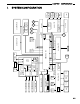
K-ID ID UP/ DOWN Fuser fan Y-ID Belt thermistor M-ID EEPROM C-ID Environment sensor High-voltage I/F, fan control, cover-open High-voltage PCB Coveropen sensor Option RAM Flash ROM CPU DCON I/F LSYNC CC1 ASIC K toner Y toner M toner C toner sensor sensor sensor sensor ID fuse-cut Toner sensor PCB Operator panel PCB C LED HEAD M LED HEAD Y LED HEAD K LED HEAD CU FAN CUPCB USB RFID 1st P.
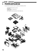
CHAPTER 1 II. CONFIGURATION PRINTER CONFIGURATION The internal part of the AR-C265P printer is composed of the following sections: • • • • • Air flow 1-2 Electrophotographic processing section Paper paths Control sections (CU sect./PU sect.) Operator panel Power supply sections (High-voltage sect./low-voltage sect.
CHAPTER 1 CONFIGURATION III. COMPOSITION OF OPTIONAL ITEMS The following optional items are available for the printer: (1) Second tray AR-C265PFU (530 sheet paper tray) (2) Duplex Unit AR-C265PADU (3) Expansion Memory AR-C265SM1 (256 MB) AR-C265SM2 (512 MB) For long printing, it is recommended to add an expansion memory.
CHAPTER 1 CONFIGURATION IV. SPECIFICATIONS Division Item AR-C265P 32/26ppm 435mm External Width dimensions Depth With duplex Without duplex Height Mass 621mm 563.5,mm 340mm With duplex Approx.29kg Without duplex Approx.26kg Print width Print width Engine speed Monochrome A4 32ppm (A4) First print Color 26ppm OHP Color 9ppm*1 OHP color/ monochrome 10ppm Monochrome 8sec time(A4) Color Warm-up time Low-noise mode Resolution LED head Max.
CHAPTER 1 Division Item CONFIGURATION AR-C265P 32/26ppm Service life Printer life 420,000 pages, 5 years Print duty Max. 50,000 pages / mo. (M=L/12, A=L/12/5) MTBF Average 4,000 pages / mo. Not applicable (2.3% duty) MPBF 40,000 pages MTTR 20 minutes Toner life Starter toner Approx. 2,000 pages (Black) (5% duty) (Attached) Standard Approx. 2,000 pages (Color) Approx. 6,000 pages (Black) Approx. 5,000 pages (Color) With 1st new drum Approx. 5,200 pages (Black) Approx.
CHAPTER 1 CONFIGURATION Division Item AR-C265P 32/26ppm Paper thickness 1st tray 64~120gsm 2nd tray 64~176gsm Manual & auto (MPT) Two-sided Operator panel LCD 64-203gsm OHP sheets available 64~105gsm 16 characters in 2 line (Roman alphabet/Japanese kana) No paper size indicated LED (Color) Two (Green x1, dark amber x1) Switch Six Status Paper out Provided switch/sensor Paper low Not provided Toner low Provided (Y,M,C,K) Cover open Provided Fuser unit temp.
CHAPTER 1 Division CONFIGURATION AR-C265P Item 32/26ppm Optional Item 256,512 MB RAM set (Detachable) Tray mechanism ! Note 2nd tray mechanism Cassette Legal/universal (530 sheets) Duplex print unit Option Other 2.5" IDE HDD User- installable (40 GB hard drive) Factory settings Japan Others USB-IF logo PCL+PS model Available Windows logo Operation with UPS Available Operation with UPS (Uninterruptible power supply) is not guaranteed.
CHAPTER 1 CONFIGURATION V. INTERFACE SPECIFICATIONS A. Parallel interface specifications (N/A) B. USB interface specifications Outline of USB interface (1) Basic specifications USB (Hi-Speed USB supported) (2) Transmission mode Full speed (Max. 12Mbps ± 0.25%) High speed (Max.480Mbps ± 0.
CHAPTER 1 C.
CHAPTER 2 EXPLANATION OF OPERATION I. ELECTROPHOTOGRAPHIC PROCESSING MECHANISM............ 2-1 II. PRINTING PROCESS.......................
CHAPTER 2 I. EXPLANATION OF OPERATION ELECTROPHOTOGRAPHIC PROCESSING MECHANISM (1) Electrophotographic process The electrophotographic process is explained briefly below: 1. Charging A voltage is applied to the CH roller to electrically charge the surface of the OPC drum. 2. Exposure The LED head radiates light onto the charged OPC drum in accordance with the image signal.
CHAPTER 2 2. EXPLANATION OF OPERATION Exposure The light emitted from the LED head is radiated onto the charged surface of the OPC drum. The charge of the radiated part of the OPC drum attenuates according to the intensity of the light, forming an electrostatic latent image on the OPC drum surface. LED head Charging roller Power Supply Unit LED head -- -- - - OPC drum Paper 3.
CHAPTER 2 4. EXPLANATION OF OPERATION Transfer A sheet of paper is placed over the OPC drum surface, and an electric charge is given to the paper from its back side by the transfer roller. When a high voltage is applied to the transfer roller from the power source, the charge induced on the transfer roller moves on to the surface of the paper through the contact part between the transfer roller and the paper, the toner being attracted to the paper surface from the OPC drum surface.
CHAPTER 2 6. EXPLANATION OF OPERATION Removal of Electricity Electrically charge on the OPC drum surface decveases by exppsing the OPC drum surface after transfer to the light. Charging roller Board for the light of the removal of electricity Light for the removal of electricity OPC drum 7. Belt Cleaning Toner remaining on the transfer belt is scraped off by the belt cleaning blade and collected into the waste toner box of the transfer belt unit.
CHAPTER 2 8. EXPLANATION OF OPERATION Fuser The toner image which was transferred to the paper is applied heat and pressure as it passes between the heat roller and the backup roller, and it is therefore fused onto the paper. For the sake of safety, a thermostat is provided; it comes on to cut off the voltage supplied to the heater if the heat roller temperature rises above a certain preset temperature.
CHAPTER 2 II. EXPLANATION OF OPERATION PRINTING PROCESS The paper fed from Tray 1 or Tray 2 is carried by the paper feed roller, register roller L and transport roller. When the paper is fed from the MPT, it is carried by the MPT paper feed roller and register roller U. Then, an unfixed toner image is created on the paper transported onto the belt sequentially through the electrophotographic process of KYMC. Thereafter, the image is fixed under heat and pressure as the paper goes through the fuser unit.
CHAPTER 2 (1) EXPLANATION OF OPERATION Paper fed from 1st Tray 1. As illustrated in Figure 2-1, when the solenoid is ON, the register motor rotates (Counterclockwise turn), transporting the paper until the IN1 sensor comes ON. (When the solenoid is ON, the paper feed roller is driven.) 2. After causing the IN1 sensor to come ON, the paper is further carried over a certain distance to finally hit register roller L. (This corrects skew of the paper.) 3.
CHAPTER 2 EXPLANATION OF OPERATION (3) Transport belt 1. As the transport belt motor rotates in the direction of the arrow, the transport belt is driven. The belt unit consists of one transport roller placed immediately underneath each color drum, with a transport belt inserted in between them. As the specified voltage is applied, the transport belt and the transport rollers send the paper located on the transport belt to the fuser unit while transferring to it the toner image present on each color drum.
CHAPTER 2 (4) EXPLANATION OF OPERATION Up/down-motions of ID units 1. The up/down-motions of the ID units take place driven by the lift-up motor. 2. Figure 2-6 shows the motions of the different ID units when the printer is operated for color print. As the lift-up motor rotates (Clockwise turn), the lift-up link slides to the left, causing the ID units to come down, as can be seen in Figure 2-6. Namely, the printer is readied for color print. 3.
CHAPTER 2 (5) EXPLANATION OF OPERATION Fuser unit and paper output 1. As illustrated in Figure 2-8, the fuser unit and delivery roller are driven by the DC motor. As the fuser motor rotates (Counterclockwise turn), the heat roller is turned. This roller fixes a toner image by heat and pressure. 2. At the same time, the delivery roller rotates to output the paper.
CHAPTER 2 EXPLANATION OF OPERATION Outline of color drift correction The color drift correction is implemented reading the correction pattern that is printed on the belt with the sensor located inside the sensor shutter under the belt unit. This sensor is used to detect and correct the pattern.
CHAPTER 2 EXPLANATION OF OPERATION Error checking methods and remedial methods The color drift correction test function among the other self-diagnostic functions is employed to check errors. (page 4-21) Remedial methods against different errors • CALIBRATION (L or R), DYNAMICRANGE (L or R) Check 1: If the above indication appears, check the connected state of the sensor cable (FFC). If the connected state is found abnormal, restore it to the normal state.
CHAPTER 2 EXPLANATION OF OPERATION Outline of density correction method The density correction is implemented reading the correction pattern that is printed on the belt with the sensor located inside the sensor shutter under the belt unit. Automatic start timing of density correction: • If the environment at power-on is greatly different from the one in which previous print was executed. • If at least one or more of the four ID count values are close to those of a new product at power-on.
CHAPTER 2 EXPLANATION OF OPERATION Error checking methods and remedial methods The density correction test function among the other self-diagnostic functions is employed to check errors. (page 4-22) Remedial methods against different errors • CALIBRATION ERR, DENS SENSOR ERR Check 1: If the above indication appears, check the connected state of the sensor cable. If the connected state is found abnormal, restore it to the normal state.
CHAPTER 2 EXPLANATION OF OPERATION Principle of toner sensor detection Toner LOW is detected by the toner sensor (Reflection sensor) installed inside the printer. The shielding plate is mounted inside the ID and rotates in synchronization with toner agitation. Moreover, the ID has a shutter fitted. The shutter is synchronized with the operation lever of the toner cartridge, and the toner sensor can detect that the toner cartridge has been loaded properly.
CHAPTER 3 INSTALLATION I. CAUTIONS, AND DO’S AND DON’TS ............................................. 3-1 II. UNPACKING METHOD..................... 3-2 III. PRINTER INSTALLATION INSTRUCTIONS................................ 3-3 IV. LISTING OF COMPONENT UNITS AND ACCESSORIES ........................ 3-4 V. ASSEMBLING METHOD................... 3-5 A. Assembly of printer main body..... 3-5 B. C. D. VI. VII. VIII. Connection of power cable......... 3-11 Installation of optional items.......
CHAPTER 3 I. INSTALLATION CAUTIONS, AND DO’S AND DON’TS • Do not install the printer at high temperature or near fire. • Do not install the printer in a location where chemical reaction can take place (laboratory, etc.). • Do not install the printer in the proximities of inflammable solvents, such as alcohol, paint thinner, etc. • Do not install the printer within reach of small children. • Do not install the printer in an unstable location (e.g., on a rickety bench or grade).
CHAPTER 3 INSTALLATION • • • • • • • Do not install the printer in a location where its vent hole is blocked. Do not install the printer directly on a shaggy carpet or rug. Do not install the printer in a sealed room or other location with poor ventilation or permeability. Install the printer away from a heavy magnetic field or noise source. Install the printer away from a video monitor or TV. To move the printer, hold it by both sides of it. This printer, which weighs Approx. 29kg (with Duplex)/Approx.
CHAPTER 3 INSTALLATION III. PRINTER INSTALLATION INSTRUCTIONS • • • Install the printer in a location where the following temperature and humidity are met: Ambient temperature: 10 - 32˚C Ambient humidity: 20 - 80 %RH(Relative humidity) Max. wet-bulb temperature: 25˚C Use caution to avoid dew condensation. If the printer is installed in a location with ambient relative humidity below 30%, use a humidifier or antistatic mat.
CHAPTER 3 INSTALLATION IV. LISTING OF COMPONENT UNITS AND ACCESSORIES • • • Check to make sure that the component units are free from damage, dirt or other irregularities in the appearance. Ensure that none of the accessories to the units is missing and that they are free from breakage or other flaw. If any irregularity is discovered, contact User Management Section for instructions. Personal injuries may occur. Make sure to lift up this printer by two or more persons, since it weighs Approx.
CHAPTER 3 V. A. INSTALLATION ASSEMBLING METHOD Assembly of printer main body Removing the protective materials 1) Peel off the protective tapes (5) and the slip of paper from the front part of the printer, and also peel off the protective tapes (2) from the back of the printer. Slip of paper Protective Tape Protective Tape 2) Draw out the paper cassette. 3) Pull out the retainer forward. 4) Open the top cover by pressing the OPEN button.
CHAPTER 3 INSTALLATION Installing the image drum cartridges 1) Take out the image drum cartridges (4) gently along with the toner cartridges attached. Note! • The image drum (Green tubular section) is extremely vulnerable. Exert good caution in handling it. • Do not expose the image drum cartridges to direct sun or intense light (1500 lux or more). Do not expose them to the room lighting for over five minutes. • In the above operation, be careful not to actuate the blue lever of the toner cartridge.
CHAPTER 3 INSTALLATION 4) Match the label colors of the image drum cartridges to those on the printer. 5) Gently put the image drum cartridges (4) back in their respective positions. Label Image drum cartridge Labels 6) Turn the blue levers (4) of the toner cartridges fully into the direction of the arrow. Note! • The starter toners (Toner cartridges supplied with the product) can print approximately 1500 A4-size sheets with 5% print density.
CHAPTER 3 INSTALLATION 1) Pull out the paper cassette. Note! Do not peel off the rubber attached to the plate. 2) Set the paper stopper securely, according to the paper size. Paper guide Paper stopper Plate 3) Loosen the paper well and line up its vertical and lateral edges. 4) Load the paper with the print face down. Note! • Place the paper aligned to the forward end of the paper cassette. • Load the paper by avoiding to exceed the ( ) mark of the paper guide. (300 sheets of 70kg ream weight paper).
CHAPTER 3 INSTALLATION Loading paper in the multi-purpose tray 1) Open the multi-purpose tray and also the paper supporter. Multi-purpose tray 2) Set the manual feed guide to the paper size. 3) Line up the vertical and lateral edges of the paper. Manual feed guide Multi-purpose tray Paper supporter Manual feed guide 4) Insert the paper, print-face up, along the manual feed guide straight as far as it will go. mark 5) Press the set button.
CHAPTER 3 INSTALLATION Storing the Quick Guide Paste the dedicated Quick Guide bag to the printer, and put the Quick Guide in it. Turning back the dedicated Quick Guide bag and peeling off the adhesive double coated tapes (2). Adhesive double coated tapes Pasting the dedicated bag to the printer. Quick Guide Vent hole Dedicated Quick Guide bag Note! When pasting the bag, avoid blocking the vent hole of the printer.
CHAPTER 3 B. INSTALLATION Connection of power cable Power requirements • Observe the following conditions: AC: 115 V ± 10% Power frequency: 60Hz ± 2Hz Approx. • If the available power is unstable, have it inspected and corrected by a qualified electrician. • The maximum power consumption of this printer is 1200W. Ensure that the power source offers an ample margin in the power capacity. It may expose you to electric shocks or cause a fire.
CHAPTER 3 INSTALLATION During holidays or a trip out of town, unplug the power cord. Connecting the power cord Note! Ensure that the power switch is in OFF (O). 1) Insert the power cord into the printer. 2) After connecting the grounding wire to the ground terminal of the power outlet, insert the power plug into the power outlet.
CHAPTER 3 INSTALLATION Turning off the power On the AR-C265P which is not equipped with the built-in type hard disk (optional) the power can be turned off as is. O I Note! Do not turn off the power while the printer is printing. On the AR-C265P equipped with the built-in type hard disk (optional), do not outright turn off the power, but follow the procedure described below. Note! • Abrupt disconnection of the power could damage the built-in hard type disk, disabling it.
CHAPTER 3 C. INSTALLATION Installation of optional items (1) Installation of expansion memory set AR-C265P expansion memory Memory volume Model name (Total memory volume) None (Standard) 256MB (256MB) AR-C265SM1 +256MB (512MB) AR-C265SM2 +512MB (768MB) Note! • Be sure to use genuine Sharp parts. If any other parts are used, the printer will not function. • Adding 64-MB memory is recommended for (600 x 600dpi x 2bit) banner-sheet printing.
CHAPTER 3 INSTALLATION Remove Side Cover 1) Loosen the screw (1). 2) Remove the side cover. To remove the side cover, slide it while holding up its upper part. Top cover 1 Screw Front cover Side cover 2 Installing the memory 1) Before taking the memory out of the bag, place the bag in contact with a metal part to fuser eliminate its static electricity. 2) Insert the memory into the idle slot. 3) Ensure that it is securely fastened by the right and left lock levers.
CHAPTER 3 INSTALLATION Attaching the side cover 1) Mount the side cover. 2) Fasten it with the screw (1). 3) Close the top cover and front cover. Top cover 3 Front cover 2 Screw 3 Side cover 1 (2) Installation of second tray unit This tray is intended to increase the amount of paper that can be loaded in the printer. It holds 530 sheets of 70kg ream weight paper, allowing to print 930 sheets continuously when combined with the standard paper cassette and multi-purpose tray.
CHAPTER 3 INSTALLATION Placing the printer on the second tray unit. Note! The printer weighs Approx. 29kg (with Duplex)/Approx. 26kg (w/o Duplex). It should be lifted up by two or more persons. 1) Align the holes in the bottom of the printer to the protrusions of the second tray unit. 2) Place the printer gently on the second tray unit. To detach the second tray unit, follow the same procedure inversely.
CHAPTER 3 INSTALLATION Peeling the protective tapes off the duplex unit Protective tapes (2) Install Duplex Unit 1) Insert the duplex unit into the lower part on the back of the printer as far as it will go. 2) Ensure that the claw on either side of the duplex unit is securely accommodated in the hole of the printer. Holes Claws Two-sided print unit (4) Installation of built-in type hard disk This is a built-in type hard disk to be added to the printer.
CHAPTER 3 INSTALLATION Turning OFF the printer power and disconnecting the power cord and printer cable Note! If an expansion memory is installed with the power switched on, the printer may be broken. O I Opening the top cover and front cover 1) Open the top cover by pressing the OPEN button. Top cover Front cover OPEN button Handle 2) Push up the handle located in the center of the front cover and pull the front cover forward.
CHAPTER 3 INSTALLATION Detaching the side cover 1) Loosen the screw (1). 2) Remove the side cover. To remove the side cover, slide it while holding up its upper part. Top cover 1 Screw Front cover Side cover 2 Memo If you have difficult detaching the side cover, check to see if the front cover is open.
CHAPTER 3 INSTALLATION Attaching the side cover 1) Mount the side cover. 2) Fasten it with the screw (1). 3) Close the top cover and front cover. Top cover 3 Front cover 2 Screw 3 Side cover 1 Connecting the power cord and printer cable to the printer, and turning on the power Executing the Menu Map print, and ensuring that the built-in type hard disk has been installed properly. 1) Execute the Menu Map print. Conduct the Menu Map print by referring to "VI. Menu Map print.
CHAPTER 3 D. INSTALLATION Confirmation of recognition of optional items To check to see whether or not the optional items have been installed properly, execute the Menu Map print by referring to "VI. Menu Map print". (1) Confirmation of recognition of expansion memory Checking the contents of the Menu Map. Check the total memory volume indicated in "Total Memory Size" of the header.
CHAPTER 3 INSTALLATION VI. MENU MAP PRINT This print is intended to ensure that the printer operates normally. 1) Load Letter paper in the tray. 2) Press the "Menu +" switch several times to cause [Information Menu] to be displayed. 3) Press the "Set" switch to cause [PRINT MENU MAP/EXECUTE] to appear. 4) Press the "Set" switch. The Menu Map print will get under way. (Two pages) When [Network] is displayed and the "Set" switch is pressed in (3) above, network information will be printed.
CHAPTER 3 INSTALLATION VII. CONNECTION METHODS Preparing a USB cable Note! • No printer cable is supplied with the printer. Provide one separately. • Prepare a USB type cable separately. • When connection is to be made in "Hi-Speed" mode of USB2.0, use a USB cable conforming to the Hi-Speed specification. Switching OFF the printer and computer Memo The USB cable can be plugged in or unplugged with the computer and printer switched ON.
CHAPTER 3 INSTALLATION Preparing a LAN cable Switching off the printer and computer 1) Plug the Ethernet cable into the Network interface connector of the printer. 2) Insert the Ethernet cable into the hub. Network interface connector VIII. CONFIRMATION OF PAPER USED BY THE USER Load the media used by the user in the printer, make Media Type/Weight settings, execute the Menu Map/Demo print, and check to make sure that the printouts are free from toner flaking.
CHAPTER 4 REPLACEMENT OF PARTS I. A. II. A. B. C. D. E. F. G. H. I. J. K. L. PRECAUTIONS ON THE REPLACEMENT OF PARTS............. 4-1 Maintenance tools ........................ 4-2 PART REPLACEMENT METHODS......................................... 4-3 Left side cover.............................. 4-3 Right side cover ........................... 4-4 Face-up tray ................................. 4-5 Rear cover.................................... 4-6 LED assy/LED assy springs ........ 4-7 Control PCB .......
CHAPTER 4 REPLACEMENT OF PARTS This section explains the field replacement procedures for parts, assemblies and component units. While those replacement procedures refer to the disassembling of parts, follow the same procedures inversely for reassembling them. The part numbers (1, 2, etc.) employed in this manual are different from those assigned in the corresponding documentation. I.
CHAPTER 4 A. REPLACEMENT OF PARTS Maintenance tools Tools necessary to replace printed-circuit boards and component units. No. Service Tools Q' ty 1 No. 2-200 Philips screwdriver, Magnetized 1 2 No. 3-100 screwdriver 1 3 No. 5-200 screwdriver 1 4 Digital multimeter 1 5 Pliers 1 6 Handy cleaner 1 7 LED Head cleaner 1 8 E-ring pliers 1 Place of use Remarks 3~5 mm screws Cleans LED head Tools necessary for using maintenance utilities. No.
CHAPTER 4 II. REPLACEMENT OF PARTS PART REPLACEMENT METHODS This subsection explains the replacement methods for the parts and assemblies illustrated in the disassembly system diagram below. A. Left side cover (1) Open the top cover. (2) Open the feeder unit. (3) Remove screw (silver) 1, and detach left side cover 2. (Tool No.
CHAPTER 4 B. REPLACEMENT OF PARTS Right side cover (1) Open the top cover. (2) Open the feeder unit. (3) Loosen screw 1, and detach right side cover 2. (Tool No.
CHAPTER 4 C. REPLACEMENT OF PARTS Face-up tray (1) Open face-up tray 1 into the direction of the arrow, free the engagement on either side of it while deflecting the tray, and remove the tray.
CHAPTER 4 D. REPLACEMENT OF PARTS Rear cover (1) Open the face-up tray. (2) Remove two screws (silver) 1. (Tool No. 1) (3) Insert the flat-tipped screwdriver (Tool No. 3) into hole A, as illustrated in Figure (2), and release two claws A. (4) Now, release two claws B, and pull the upper part of rear cover 2 in the direction of arrow A. (5) Push the lower part of rear cover 2 in the direction of arrow B, as shown in Figure (3), and detach rear cover 2 by freeing three claws C.
CHAPTER 4 E. REPLACEMENT OF PARTS LED assy/LED assy springs (1) Open the top cover. (2) After disconnecting the cable, first free hook part A by applying force in the direction of the arrow, as illustrated in Figure (2), and then, free hook part B, to finally remove LED Assy 1. (In this operation, two springs2will come out together with LED Assy 1.
CHAPTER 4 F. REPLACEMENT OF PARTS Control PCB (1) Open the top cover. (2) Detach the right side cover. (See Section "B. Right side cover".) (3) Remove eight screws (silver) 1, and detach plate shield assembly (PCL) 2 by releasing connector claws A. (Tool No. 1) (4) Remove screw 3, and disconnect head cable 4. (Tool No. 1) (5) Remove seven screws (silver) 5, disconnect all the cables, and disassemble control PCB 6 (TBH-1 PCB). (Tool No.
CHAPTER 4 G. REPLACEMENT OF PARTS Print engine controller PCB (1) Remove the plate shield Assy(PCL/GDI). (See Section "F. Control PCB" (1) through (3).) (2) Remove all the connectors and two screws (silver) 1, and disassemble the print engine controller PCB 2. (Tool No.
CHAPTER 4 REPLACEMENT OF PARTS Toner sensor Control panel RFID ID motor Controller PCB Fuser motor PE cable SSNS cable Paper feed motor Low-voltage fan Option (DUP & 2nd) Junction PCB High-voltage power supply Paper feed solenoid Option (2ND) cable Belt & IPUD motor Low-voltage power cable HSOL DCHEAT HOP FSNS PE CUIF SSNS DCID RFID OPE Cable route diagram of print engine controller PCB POWFAN BELTIDUP HVOLT RELAY OPTION POWER Connection diagram of print engine controller PCB 4-
CHAPTER 4 H. REPLACEMENT OF PARTS Top cover assembly (1) Detach the left side cover. (See Section "A. Left side cover".) (2) Detach the right side cover. (See Section "B. Right side cover".) (3) Detach the rear cover. (See Section "D. Rear cover".) (4) Remove the plate assembly shield (GDI), and then, the control PCB. (See Section "F. Control PCB".) (5) After unplugging the connector, disconnect hooked RFID cable 1.
CHAPTER 4 I. REPLACEMENT OF PARTS Top cover (1) Detach the top cover assembly. (See Section "H. Top cover assembly".) (2) Remove ten screws (black) 1, and detach cable cover 2 and top cover 3. (Tool No.
CHAPTER 4 J. REPLACEMENT OF PARTS Controller panel assy (1) Open the top cover. (2) Open the feeder unit. (3) Detach the right side cover. (See Section "C. Face up tray".) (4) Remove the plate shield assembly. [See Section "G. Print engine controller PCB" (2).] (5) After unplugging the connector of the control panel assembly, free the hook. (6) Remove four screws (silver) 1, and detach control panel Assy 2. (Tool No.
CHAPTER 4 K. REPLACEMENT OF PARTS Board PRP/Top cover handle (1) Detach the control panel assembly. (See Section "J. Controller panel assy".) (2) Release two claws A, as illustrated in Figure (2), and remove frame OP1, lever lock 2 and spring compression 3. (3) Release two claws B by forcing in the flat-tipped screwdriver (Tool No. 3), and remove the cover assembly OP4 and spring torsion 5.
CHAPTER 4 L. REPLACEMENT OF PARTS Low-voltage power supply/low-voltage fan/hopping motor/fuser motor (1) Remove the cassette assembly. (2) Disassemble the print engine controller PCB. (See Section "G. Print engine controller PCB".) (3) Disassemble the control PCB. (See Section "F. Control PCB".) (4) Disconnect all the cables from the Guide Cable PowerLow. (5) Unplug the fuser I/F connector from the low-voltage power supply, and remove Guide Cable PowerLow 1 by releasing the two claws.
CHAPTER 4 M. REPLACEMENT OF PARTS Guide eject assy/color register assy/board-PRY (1) Detach the left side cover, right side cover, rear cover, and top cover assembly. (See Sections "A", "B", "D", and "H".) (2) Remove the print engine controller PCB, control PCB, and low-voltage power supply. (See Sections "F", "G", and "L" (3).
CHAPTER 4 REPLACEMENT OF PARTS Heater thermistor & F cut (Black & white) Exit sensor Heater AC (Black & white) Belt thermistor Belt motor Belt thermistor Color registration sensor Color registration sensor Density sensor REPLAY Board-PRY Belt motor (To print engine controller PCB) Board-PRY Cable Route Diagram Left color registration sensor PCB (PRC PCB) Right color registration sensor PCB (PRC PCB) SNS SNS CN CN Density sensor RCR Fuser unit I/F connector DENS LCR FUSER EXIT Exit sen
CHAPTER 4 N. REPLACEMENT OF PARTS Fan (fuser)/belt motor/high-voltage power supply board/cover-open switch (1) Detach the left side cover. (See Section "A. Left side cover".) (2) Remove screw (silver) 1, unplug the connector, and disassemble belt motor 2. (Tool No. 1) (3) Detach rear cover 3. (See Section "D. Rear cover".) (4) Unplug the connector, and remove Fan (Fuser) 4 by turning it clockwise. (5) Free the connector and two claws A, and remove cover-open switch 5.
CHAPTER 4 O. REPLACEMENT OF PARTS MPT assy (1) Open MPT Assy 1. (2) Release the two stoppers by opening the two arms of MPT Assy 1 toward the outside, pull the assembly in the direction of the arrow to free the two fulcrums, and detach MPT Assy 1.
CHAPTER 4 P. REPLACEMENT OF PARTS Feeder unit/board-RSF/MPT hopping roller/frame assy separator/ cover front (1) Open the top cover. (2) Remove the plate shield, and unplug the connector. (See Section "F".) (3) Free the claws of Stay L 1 and Stay R 2, and remove feeder unit 3 by sliding it to the right. (4) Detach the motor cover. (See Section "L" .) (5) Disassemble cover sensor 4 by freeing the claw. (6) Unplug the connector, and disassemble Board-RSF 5. (7) Remove MPT Assy.
CHAPTER 4 Q. REPLACEMENT OF PARTS Board-PRZ lift-up motor/solenoid/paper-end sensor (1) Detach the left side cover, right side cover, rear cover, top cover unit, and feeder unit. (See Sections "A", "B", "D", "H" and "P".) (2) Disassemble the print engine controller PCB and control PCB. (See Section "F", "G" and "L" (3).) (3) Remove the guide cable Power Low, low-voltage power supply, and low-voltage fan. (See Section "L".) (4) Remove the cover driver, Board-PRY, color register Assy, and eject assembly.
CHAPTER 4 REPLACEMENT OF PARTS 9 View A G 6 E 1 2 H I A C D K O P N O D I R 3 8 6 B C 8 L M B T Q 4 U XW 1 5 4 V 5 G 6 Z Install 4 aligninig the two position cut as mark figure. Y [ Lift-up motor Install G aligninig the two position cut as mark figure. E Align the motor and connector in position to the arrow. View A ( I) Lever-Solenoid ( R) 4-( B ) Fit position arrow of B (Gear-Idle-Drum Z24-102) and the arrow of (Cover-PlateR-Assy-PX734) of each color.
CHAPTER 4 R. REPLACEMENT OF PARTS Feed roller (1) Remove the cassette. (2) Release the latch, and remove feed roller 1.
CHAPTER 4 S. REPLACEMENT OF PARTS Shaft eject assy(FU)/shaft eject assy(FD)/eject sensor (1) Remove the eject Assy. (See Section "M. Guide eject assy / color register assy / board-PRY") (2) Free the two claws, and divide the Assy between guide into lower 1 and guide eject upper 2. (3) Remove gear idle eject 3, and disassemble shaft Assy eject (FU) 4 and shaft Assy eject (FD) 5. (4) Remove lever eject sensor 6 and eject sensor 7.
CHAPTER 4 T. REPLACEMENT OF PARTS Fuser Unit (1) Open the top cover. (2) Lift up the lock levers 1 (2, blue) of the fuser unit in the direction of the arrow, and remove fuser unit 2.
CHAPTER 4 U. REPLACEMENT OF PARTS Belt Unit (1) Open the top cover. (2) Remove ID unit 1. (3) Turn the lock levers (2, blue) of belt unit 2 in the direction of the arrow , and hold belt unit 2 by the levers (Blue) to remove it.
CHAPTER 4 REPLACEMENT OF PARTS III. LUBRICATING POINTS This subsection indicates the lubricating points of the printer. Conversely, it means that any other parts than the specified lubricating points must not be lubricated. There is no need to lubricate in the midst of a disassembling job. However, if lubricating oil has been wiped off, supply the specified oil.
CHAPTER 4 REPLACEMENT OF PARTS 1 0ZZ43070301// Plate-Assy.
CHAPTER 4 REPLACEMENT OF PARTS 2 0ZZ42049701// Guide-Assy.-Cassette-L Apply a normal amount of Molycoat(EM-30L) to the hatched portions Guide-Casette-L EM-30L Class C 3 0ZZ43294901// Guide-Assy.
CHAPTER 4 REPLACEMENT OF PARTS 4 0ZZ43073201// Gear-Assy.-HP Holder-Gear-A Apply a normal amount of Molycoat(EM-30L) to the hatched areas EM-30L Class C 5-1 0ZZ43070501// Plate-Ass.
CHAPTER 4 REPLACEMENT OF PARTS 5-2 0ZZ43070501// Plate-Ass.-Side-R Gear-LiftUp-Z21Z34 Apply a normal amount of Molycoat(EM-30L) to the hatched areas EM-30L Class C Do not apply grease here Gear-LiftUp-Z21Z34 Apply a normal amount of Molycoat(EM-30L) to the hatched areas EM-30L Class C Gear-Idle-Z44 Gear-Idle-DrumZ24-102 Apply MOLYKOTE (EM-30L) in a large quantity to the gear tooth flanks at over 120 deg. EM-30L Class F Enlarged view 5-3 0ZZ43070501// Plate-Ass.
CHAPTER 4 REPLACEMENT OF PARTS 5-4 0ZZ43070501// Plate-Ass.-Side-R Apply MOLYKOTE (EM-30L) in a small quantity to the hatched parts. EM-30L ClassA Apply MOLYKOTE (EM-30L) in a normal quantity to the gear tooth tip. EM-30L ClassC Gear-LiftupR-Z56 Link-Liftup-R (5) Gear-LiftupR-Z32 Motor-Pulse-Liftup Gear-IdleLiftup-Z28 Gear-Liftup-Z121Z32 Apply MOLYKOTE (EM-30L) in a small quantity to the hatched parts.
CHAPTER 4 REPLACEMENT OF PARTS 6 0 Z Z 4 3 0 7 4 9 0 1 / / Plate-Ass.-Side-L Apply MOLYKOTE (EM-30L) in a normal quantity to the gear tooth tips. EM-30L Class C Apply MOLYKOTE (EM-30L) in a normal quantity to the post. EM-30L Class C Apply MOLYKOTE (EM-30L) in a small quantity to the hatched part.
CHAPTER 4 REPLACEMENT OF PARTS 7 0ZZ42071401// Holder Assy.-Regist-L Apply MOLYKOTE (EM-30L) in a normal quantity to the hatched parts (parts having the rotation shafts inserted). Holder-Regist-L EM-30L Class C 8 0ZZ42071901// Holder Assy.-Regist-R Holder-Regist-R Apply MOLYKOTE (EM-30L) in a normal quantity to the hatched parts (parts having the rotation shafts inserted).
CHAPTER 4 REPLACEMENT OF PARTS 9 0ZZ43122601// Fuser-Assy Cam-Release Lever-Release Plate-Side-R-Caulking(Fuser) Class C Apply HP-300(normal amount) to hatched area Gear-Fuser-(Z35) Do not apply grease to the boss. Gear-Idle-(Z21) Do not apply grease to the gears. 0 0ZZ43070401// Cassette-Assy Assemble after applying MOLYKOTE (EM-30L) to the hatched parts in the illustration below (both right and left).
CHAPTER 4 REPLACEMENT OF PARTS A 0ZZ43301501// Guide-Assy.-Eject-L Guide-Eject-Upper Apply MOLYKOTE (EM-30L) in a normal quantity to the gear tooth flanks, shaft surfaces and flanges (6 points). Grease must not stick to the paper paths. EM-30L Class C Shaft-Assy.-Eject(FD) Apply MOLYKOTE (EM-30L) in a normal quantity to the bearings (2 points). EM-30L Class D Apply MOLYKOTE (EM-30L) in a normal quantity to the shaft surfaces (6 points). Grease must not stick to the paper paths. Shaft-Assy.
CHAPTER 4 REPLACEMENT OF PARTS B 0 Z Z 4 3 0 7 0 2 0 1 / / Frame-Assy.-Base Apply PM in a small quantity to the hatched part. (1) Applying method: Wipe the part with a cloth slightly impregnated with PM. (2) After applying PM, insert and pull out the cassette several times to ensure that no noise is emitted. PM Class C Cassette-Assy.
CHAPTER 4 REPLACEMENT OF PARTS C-1 0ZZ43070101// Printer-Unit Apply MOLYKOTE (EM-30L) in a normal quantity to the tips of the terminals (4 points). Plate-Ass.-Side-L Applied range of grease (4 points) EM-30L Class C Plate-Driver-PU(Caulking) Apply MOLYKOTE (EM-30L) in a normal quantity to the post. EM-30L Class C Gear-Idle-Belt Apply MOLYKOTE (EM-30L) in a normal quantity to the gear tooth flanks. EM-30L Class C Apply MOLYKOTE (EM-30L) in a normal quantity to the end face.
CHAPTER 4 REPLACEMENT OF PARTS C-2 0ZZ43070101// Printer-Unit Apply MOLYKOTE (EM-30L) in a normal quantity to the hatched parts. EM-30L Class C Plate-Ass.-Side-R Spring-Torsion-L Apply PM to the slot parts of the solid coiling of this torsion spring using a brush.
CHAPTER 4 REPLACEMENT OF PARTS D 0 Z Z 4 3 0 7 9 6 0 1 P A / / Belt-Unit Apply MOLYKOTE (EM-30L) in a small quantity to the inside of Bearing-TR (Belt) (4 points). Apply MOLYKOTE (EM-30L) in a normal quantity to the bearings (both sides). EM-30L Class C EM-30L Class A Enlarged view Enlarged view 4-40 Apply MOLYKOTE (EM-30L) in a small quantity to the inside of Bearing-TR (Belt) (4 points). EM-30L Class C Apply MOLYKOTE (EM-30L) in a normal quantity to the bearings (both sides).
CHAPTER 4 REPLACEMENT OF PARTS E 0ZZ42626501// Sensor-Assy-Color-Regist Plate-Sensor-C.Regist Shaft-Cover-Sensor Apply MOLYKOTE (EM-30L) in a small quantity to the hatched parts (At both Sides)(8 points). EM-30L Class A MOLYKOTE must not stick to the surfaces of Cover Sensor-C. Regist. Cover-Sensor-C.
CHAPTER 4 REPLACEMENT OF PARTS F 0ZZ43081301// Roller-Assy.-Idle(FD) 1 2 Disassembled view Grease applying method: Before assembling 2 to 1, apply MOLYKOTE (EM-30L) in a very small quantity (Class S) to the sliding parts (hatched parts) between 1 and 2.
CHAPTER 4 REPLACEMENT OF PARTS G 0ZZ43301601// Roller-Assy.-BIAS(FU)C 2 3 1 Grease applying method: Range in which grease must not stick Before assembling 3 to 2, apply MOLYKOTE (EM-30L) in a very small quantity (Class S) to the sliding parts (hatched parts) of 2.
CHAPTER 5 MAINTENANCE MENUS I. SYSTEM MAINTENANCE MENU (FOR MAINTENANCE PERSONNEL) ................................... 5-1 II. MAINTENANCE UTILITY .................. 5-3 III. FUNCTIONS OF USER’S MAINTENANCE MENU..................... 5-6 A. Maintenance menu (For end users) ........................................... 5-6 B. Self-diagnostic mode.................... 5-7 IV. SETUP AFTER REPLACEMENT OF PARTS....................................... 5-40 A. Precautions on the replacement of engine control PCB ..
CHAPTER 5 MAINTENANCE MENUS The adjustment of this printer can be implemented using the maintenance utility and also by key input through the operator panel. This printer provides maintenance menus, apart from the normal menus. Select the menu that best suits the purpose of your intended adjustment. I. SYSTEM MAINTENANCE MENU (FOR MAINTENANCE PERSONNEL) This menu is activated when the power is turned with the MENU+ and MENU- keys held down.
CHAPTER 5 MAINTENANCE MENUS Maintenance menu indication table (2/2) Category Value(2nd Line) DF CONFIG MENU CODESET TYPE1 TYPE2 TEST PRINT MENU TEST PRINT MENU ENABLE DISABLE * ENABLE DISABLE * EXECUTE - PAGE CNT PRINT FUSE KEEP MODE 5-2 Item(1st Line) PAGE CNT PRINT FUSE KEEP MODE *J *E Function Function This menu is displayed on the printers for all destinations. TYPE1: Does not indicate Russian/ Greek. TYPE2: Indicates Russian/Greek.
CHAPTER 5 II. MAINTENANCE MENUS MAINTENANCE UTILITY The maintenance utility is used to perform the adjustments of "Maintenance Utility Adjustment ItemsTable" below. Details of the maintenance utility are described below. (1) Maintenance Utility Operation Manual: 0 Z Z 4 2 6 7 8 8 0 1 F U 0 2 / / Rev5 or later (English) Maintenance Utility Adjustment Items (1/3) Item Adjustment Operation on Section No. of the Operator Panel Maintenance Utility (Section No.
CHAPTER 5 MAINTENANCE MENUS Maintenance Utility Adjustment Items (2/3) Item Adjustment Operation on Section No. of the Operator Panel Maintenance Utility (Section No. corresponds to Operation the Maintenance manual) 5 Serial Number information setup Selection of the printer serial number recorded Subsect.2.4.1.1.4.3 Invalid operation on the CU, and rewrite of the output mode and device serial numbers. 6 Set information of PCB items Verification of the serial No.
CHAPTER 5 MAINTENANCE MENUS Maintenance Utility Adjustment Items (3/3) Item Adjustment Operation on Section No. of the Operator Panel Maintenance Utility (Section No. corresponds to Operation the Maintenance manual) 20 Destination/PnP data Setting Check/setting of destination of the printer (CU), device ID, USB ID Section 2.4.1.2.6 18 Display of the Consumable Counter Confirmation of the current value of the Section 2.4.1.3.
CHAPTER 5 MAINTENANCE MENUS III. FUNCTIONS OF USER’S MAINTENANCE MENU A. Maintenance menu (For end users) There is a maintenance menu category among the normal menu categories. (Different from the system maintenance menus) The items that can be set under this menu are indicated below. Maintenance Menu Values in shaded areas are initial settings. Operator Panel Display Category Maintenance Menu Item (Upper Display) Value (Lower Display) Function MENU RESET EXECUTE Initializes menu settings.
CHAPTER 5 B. MAINTENANCE MENUS Self-diagnostic mode Operator panel The explanation of the operations relating to the self-diagnosis presupposes the (1) Transition of menu items Self-diagnostic mode layout (Overall) xxxxx xxxxx Level transition is possible only when a part is displayed. Transition of is activated with [MENU-] or [MENU+]. POWER ON Not pressed Hold down [MENU+] and [MENU-], until the system maintenance menu is displayed. Then, select ENGINE DIAG MODE and press [ENTER].
CHAPTER 5 MAINTENANCE MENUS (1) Switchover of menu items LEVEL0 The transition of xxxxx is activated when [BACK] or [ONLINE] is pressed and held down, or [MENU+] or [MENU-] is pressed briefly. The transition of xxxxx is activated with [MENU+] or [MENU-]. The item selection screen is restored when [BACK] is pressed and held down.
A ENGINE DIAG LEVEL1 LEVEL1 [MENU+] B [MENU-] K-ID UNIT Y-ID UNIT M-ID UNIT C-ID UNIT FUSER UNIT TR BELT UNIT K-TONER (FULL) Y-TONER (FULL) M-TONER (FULL) C-TONER (FULL) M-WASTE TNR CNT C-WASTE TNR CNT K-STC MODE CNT Y-STC MODE CNT M-STC MODE CNT C-STC MODE CNT K REFILL CNT Y REFILL CNT M REFILL CNT C REFILL CNT K OVER RIDE CNT Y OVER RIDE CNT M OVER RIDE CNT C OVER RIDE CNT CONSUMABLE STATUS F-RL SL BL DT-DC T1 PE_PNE_CVO T1 CASETTE SIZE T2 PE_PNE_CVO_CA T2 HOP_LF_FED T2 CASETTE SIZE DUP IN_RA_FNT
CHAPTER 5 MAINTENANCE MENUS Normal self-diagnostic mode (Level 1) The menus of the normal self-diagnostic mode are indicated below.
CHAPTER 5 MAINTENANCE MENUS Activation method for self-diagnostic mode (Level 1) 1. The system maintenance menu mode is activated when the power is turned on with the MENU+ and MENU- keys held down simultaneously 2. Press the MENU+ or MENU- key several times, until "ENGINE DIAG MODE" is displayed. Pressing the ENTER key causes "DIAGNOSTIC MODE" to appear. DIAGNOSTIC MODE XX.XX.XX FACTORY/SHIPPING 3. XX.XX.XX of "DIAGNOSTIC MODE XX.XX.
CHAPTER 5 MAINTENANCE MENUS RFID antenna M RFID antenna K RFID antenna C Toner sensor C Toner sensor M Toner sensor Y Toner sensor K RFID antenna Y Fuser unit thermistor Upper Cover-open SW Write sensor Fuser unit thermistor Upper, compensation Inlet sensor 2 Exit sensor Duplex print inlet sensor Inlet sensor 1 Temperature & humidity sensor Duplex print cover-open sensor Tray 1 paper-end sensor Tray 2 inlet sensor Tray 2 paper-end sensor Duplex print bottom sensor Duplex print rear sensor Belt
Detail Display AD value: ***H Upper-Center-Thermister Hum Sns HT THERMISTER HUM_TEMP_DEN BELT_T ID UP/DOWN RFID COLOR L*2 F-RL SL BL DT-DC*1 T1 PE_PNE_CVO T1 CASETTE SIZE*1 T2 PE_PNE_CVO_CA 2nd-Paper-End Sns T2 HOP_LF_FED T2 CASETTE SIZE*1 DUP IN_RA_FNT DUP SK_CVO 5 6 7 8 9 10 11 12 13 14 15 16 17 Dup-Stack Sns(In2) Dup-In Sns 1st-Paper-End Sns TAG-K present/absent Belt-Thermister Lower-Center-Thermister AD value: ***H Aligment-Left-Sns REG L/R_OHP_WG 4 H:Paper out L:
CHAPTER 5 MAINTENANCE MENUS Motor clutch test This self-diagnosis is practiced to test motors and clutches. 1. Activate the self-diagnostic mode (Level 1), press and hold down the MENU+ or MENU- key, until "MOTOR & CLUTCH TEST" appears in the upper line of the display section, and then, press the ENTER key. (The MENU+ key increments a test item, and the MENU- key decrements a test item.) 2.
CHAPTER 5 MAINTENANCE MENUS Fuser motor (Registration shutter) ID motor Duplex print solenoid ID Up/Down motor Duplex print clutch Tray 1 Hopping motor (Registration motor, front motor) Duplex print motor Hopping solenoid Tray 2 clutch Belt motor Tray 2 motor Description of Control for Unit Driving Unit Name ID motor To be driven with all the IDs (Black/yellow/magenta/cyan) removed. Belt motor To be driven with all the IDs (Black/yellow/magenta/cyan) removed.
CHAPTER 5 MAINTENANCE MENUS Test print This self-diagnosis is practiced to print test patterns built in PU. Other test patterns are stored in the controller. This print cannot be used to check the print quality. To diagnose abnormal images, follow Chapter 7 "Troubleshoot Procedures". 1. Activate the self-diagnostic mode (Level 1), press and hold down the MENU+ or MENU- key, until "TEST PRINT" appears in the upper line of the display section, and then, press the ENTER key.
CHAPTER 5 MAINTENANCE MENUS Notes! PAGE setup ----------------- After shifting the digit of the set value with the MENU+ key or MENUkey, press the ONLINE key. The set value will be incremented. Pressing the CANCEL key decrements it. COLOR setup --------------- Pressing the ENTER key after selecting ON causes the data indicated below to appear on the panel. Print setup for each color --- Pressing the MENU+ key or MENU- key activates shifting.
CHAPTER 5 MAINTENANCE MENUS Pattern 3 Pattern 4 Pattern 5 Pattern 6 Note! If the solid print (Pattern 7) available among the local print functions is conducted with 100% of each color, offset will take place. To prevent this offset, it will be necessary to make the print setup of each color as specified in step 3 on previous page and to limit the colors to be printed simultaneously to two or less when conducting the solid print No. 7.
CHAPTER 5 MAINTENANCE MENUS • When print is executed, the following message is displayed: P=*** W=*** P: Number of test-print pages (Unit: sheets) W: Print wait time (Unit: seconds) • Pressing the MENU+ key switches over the indication.
CHAPTER 5 • MAINTENANCE MENUS Pressing the MENU+ key switches over the indication. KID=**** YID=**** MID=**** CID=**** KID, YID, MID and CID denote the constant-speed timer values of the respective ID motors (I/O set values) [Unit: HEX]. • Pressing the MENU+ key switches over the indication.
CHAPTER 5 MAINTENANCE MENUS Color registration adjustment test This self-diagnosis is practiced to conduct testing on the color registration function of the printer and to locate the cause of color drift. Restore the normal operation of the printer by following the troubleshooting procedure if any error is issued during the color registration test. 1.
CHAPTER 5 MAINTENANCE MENUS <> The same as the key operation of Item2. in the execution of BLT REFLECT TEST. 4. Repeat Items 2 and 3, as needed. 5. Press the [BACK] key to terminate the test.
CHAPTER 5 MAINTENANCE MENUS <> The same as the key operation of Item 2 in the execution of DENS ADJ EXECUTE. <> Indication only, without functionality. <> 1 Automatic setting of a density sensor sensitivity correction value is made. ([READY] light blinking) 2 When the test ends, the test result (OK or error name) appears in the upper line of the display section, and **** RESULT, in the lower line.
CHAPTER 5 MAINTENANCE MENUS Indication of consumable part counters This self-diagnosis is practiced to indicate the consumed states of consumable parts. 1. Activate the normal self-diagnostic mode, and press and hold down the [MENU+] key or [MENU] key, until "CONSUMABLE STATUS" appears in the display section, and then, press the ENTER key. (The MENU+ key increments a test item, and the MENU- key decrements a test item.) 2.
CHAPTER 5 MAINTENANCE MENUS Indication of printed page counters This self-diagnosis is practiced to indicate the current number of printed pages of the printer. 1. Activate the normal self-diagnostic mode, and press and hold down the [MENU+] key or [MENU] key, until "PRINTER STATUS" appears in the display section, and then, press the ENTER key. (The MENU+ key increments a test item, and the MENU- key decrements a test item.) 2.
CHAPTER 5 MAINTENANCE MENUS 6. Press the [BACK] key to terminate the test. (The status of Item 1 is restored.) Indication FACTORY MODE Set value Function FACTORY MODE For setting the Factory Work mode (Fuse-cut disabled mode). SHIPPING MODE For canceling the Factory Work mode and enabling the fuse-cut function. FUSE INTACT BELT UNIT ****** For checking the FUSE status of the transfer belt unit. Note: ****** is FUSE UNIT ****** For checking the FUSE status of the fuser unit.
CHAPTER 5 MAINTENANCE MENUS 6. Press the [BACK] key (except for the status of Item 4.) to terminate the setup. (Status of Item 1 restored) Indication TONER SENSOR BELT UNIT CHECK ID UNIT CHECK UP/DOWN SENSOR REG ADJUST ERROR DRUM OVER LIFE Set value ENABLE DISABLE ENABLE DISABLE ENABLE DISABLE ENABLE DISABLE ENABLE DISABLE STOP CONTINUANCE Function Operation of set value Detects. For enabling/disabling toner sensor operation. Does not detect.
CHAPTER 5 MAINTENANCE MENUS Details of panel indications Display LCD (English) (■ ■ means no display in upper line) 5-28 Ready Attention LED LED Description Level INITIALIZING Off Off It displays, while not having determined the system display language immediately after turning on a power supply. If a display language is determined, it will change to the display of Priority 2. Initializing INITIALIZING Off Off The controller side is initializing.
CHAPTER 5 LCD (English) ■ means no display in upper line) (■ Ready Attention LED LED MAINTENANCE MENUS Description Level Initializing CHECKING FILE SYSTEM Off Off Displays that HDD file system is being checked. Process Check of File System is valid to start from "FILE SYS MAINTE2"-"CHECK FILE SYS" of Admin Menu. ERASING DISK nnn% Off Off Initializing Indicates that the hard disk is being erased. Erase process of the hard disk is valid to start from "FILE SYS MAINTE2"-"HDD ERASE" of ADMIN MENU.
CHAPTER 5 MAINTENANCE MENUS LCD (English) (■ ■ means no display in upper line) 5-30 Ready Attention Description Level LED LED PU FLASH ERROR Off Off It is shown that PU firmware has booted in Loader mode. Initializing It displays, when PU firmware returns "00.00.00" as a response of Leisus command"VERSIONR 01 H" (version of PU firmware main part program) which CU firmware transmits at the time of initialization. If initialization is completed, it will change to the status of Priority 251.
CHAPTER 5 LCD (English) ■ means no display in upper line) (■ Ready Attention LED LED MAINTENANCE MENUS Description Level PRINT NETWORK CONFIG Varies Varies It is shown that a network setup is printing. If "Print Summary", "Print Information" of each slot are chosen by menu "Print Information"-"Network", printing of a network setup will be started. Normal ■ COLLATE COPY iii/jjj Varies Varies Collate printing. iii: The number of copy in printing. jjj: the total number of printing.
CHAPTER 5 MAINTENANCE MENUS LCD (English) ■ means no display in upper line) (■ 5-32 Ready Attention LED LED Description Level ■ ADJUSTING DENSITY Varies Varies Executing Auto Density Adjustment. Status code 10988 corresponds to density reading (Leisus - STSDEN #1), thereto 10994 corresponds to density adjusting (Leisus - STSDEN #0). Normal PU DOWNLOADING Varies Varies Downloading PU F/W (This is not user-level error) This function is secret to users.
CHAPTER 5 LCD (English) (■ ■ means no display in upper line) Ready Attention LED LED MAINTENANCE MENUS Description Level ■ %COLOR% TONER REGIONAL MISMATCH Varies On The Region ID of toner cartridge is not proper to the distribution channel. %COLOR% Y M C K Warning ■ NON GENUINE %COLOR% TONER Varies On The chip of RFID is not compatible. %COLOR% Y M C K Warning ■ PS3 EMUL ERROR Blink Varies Interpreter detects an error due to the following reason.
CHAPTER 5 MAINTENANCE MENUS LCD (English) (■ ■ means no display in upper line) 5-34 Ready Attention LED LED Description Level ■ BELT LIFE Varies On Notifies the life of the belt unit (warning). Displayed in a combination of other message in the first line. Warning only (No Life error). This appears when the cover was opened and closed just after the belt life error occurred. Also this occurred instead of the belt life error, if the "BELT LIFE PRINT CONTINUE" setting was 'ON'.
CHAPTER 5 LCD (English) ■ means no display in upper line) (■ Ready Attention LED LED MAINTENANCE MENUS Description Level ■ DENSITY COLOR CALIBRATION ERROR Warning Varies Varies Density Adjustment Color Calibration Error.Error that does not occur at user level.Displayed only in FactoryMode. PU firmware does not notify this warning to CU firmware at the time of Shipping Mode. Therefore, this status does not occur in a user environment.
CHAPTER 5 MAINTENANCE MENUS LCD (English) (■ ■ means no display in upper line) 5-36 Ready Attention LED LED Description Level ■ REGISTRATION ERROR n Varies On Warning When a color registration error is detected with coarse adjustment, or with the main-scan line adjustment. PU firmware does not notify this warning to CU firmware at the time of Shipping Mode. Therefore, this status does not occur in a user environment.
CHAPTER 5 LCD (English) (■ ■ means no display in upper line) Ready Attention MAINTENANCE MENUS Description Level On Indicates that the free space of the storage device is too small to execute PRINT STATISTICS SYSTEM. Warning Varies On Notifies users that jobs have been cancelled because they are not permitted for printing. (Related to JobAccount). Stays displayed until the ON LINE key is pressed. Warning ■ LOG BUFFER FULL.
CHAPTER 5 MAINTENANCE MENUS LCD (English) ■ means no display in upper line) (■ Description Level ■ PU FLASH ERROR Varies Varies PU flush error (Error occurs during the alteration of PU farm or it failed in the alteration in PU flush of such as LED Head information.
CHAPTER 5 MAINTENANCE MENUS Various types of print on the individual printer equipped with controller Menu Map Printing Information on the program versions, controller configuration, network settings, etc., is printed. Operation: 1 Press the MENU+ key several times to cause “INFORMATION MENU” to be displayed. 2 Press the ENTER key to cause “PRINT MENUMAP/EXECUTE” to be displayed. 3 Press the ENTER key.
CHAPTER 5 MAINTENANCE MENUS IV. SETUP AFTER REPLACEMENT OF PARTS This section describes the necessary adjustments to be made when parts have been replaced. Replaced Part A. Adjustment LED Head Not necessary Image Drum Cartridge (Y, M, C, K) Not necessary Fuser Unit Not necessary Belt Unit Not necessary PU (PRX PCB) Necessary to copy EEPROM information. Utility required. CU(SP1 PCB/TBH PCB) Necessary to copy EEPROM information. Utility required.
CHAPTER 5 MAINTENANCE MENUS • To specify a PU Serial Number, enter a 11-digit number prefixed with "0" (single-byte zero). (Notice that, when the PU Serial Number is read, it is a 10-digit number.) On the "PU Serial Number setup" screen, enter the 11-digit number resulting from prefixing a single-byte zero to the 10-digit number which is obtained by excluding the two digits for Revision, shown in the image diagram below, from the serial number on the "PU Serial Number setup" screen.
CHAPTER 5 Note! MAINTENANCE MENUS When the EEPROM (engine control PCB) has been replaced, the service life information of the belt, toner, IDs, etc., is necessarily cleared. Therefore, be aware that the service life management is likely to suffer errors until the next time units are replaced. The counts that are cleared when the EEPROM is replaced are those indicated below.
CHAPTER 5 MAINTENANCE MENUS Replacement of EEPROM after replacement of TBH PCB The EEPROM of the TBH PCB is installed in the IC socket. Replace the EEPROM in the following manner: 1. Remove the EEPROM and MAC address sticker label attached to the new PCB. 2. Insert a flat-tipped screwdriver in between the EEPROM of the old PCB and the IC socket, and take out the EEPROM, seeing to it that the leads of the EEPROM are not bent. 3. Install the EEPROM in the new PCB.
CHAPTER 5 MAINTENANCE MENUS • The CU Serial Number is output in the Printer Serial Number field of the Menu Map header section. Therefore, after the CU Serial Number has been rewritten, it can be checked by conducting the Menu Map print. (2) For OEL destination • For CU Serial Number, a unique Serial Number within 12 digits is assigned at the UK Plant. • Notice that, when the CU Serial Number is set, the menu settings inside the CU are reset (restored to the default settings).
CHAPTER 5 2. MAINTENANCE MENUS Explanation PX734/735 are ROMs used in common for domestic and overseas markets. This setting is stored on the EEPROM of the SP1/TBH PCB. When the version number of the program ROM is changed, the setting will be reset to the default value. Make this setup when there is no destination set up or the version number of the program has been changed. V.
CHAPTER 6 PERIODICAL MAINTENANCE I. II. III. RECOMMENDED REPLACEMENT PARTS............................................... 6-1 CLEANING ........................................ 6-1 CLEANING OF LED LENS ARRAY .............................................. 6-1 IV. V. CLEANING OF PICKUP ROLLERS.......................................... 6-3 INTERNAL CLEANING OF PRINTER...........................................
CHAPTER 6 I. PERIODICAL MAINTENANCE RECOMMENDED REPLACEMENT PARTS Sharp recommends that heavy users only replace the following parts. (If those parts are not replaced, the print quality is not guaranteed, and malfunctions may even result.) Part Name Number Friction Pad Assy 0ZZ42088801// Roller Assy. Hopping 0ZZ43334901// Note! 1. 2. Consumable parts (Image drums, toner cartridge, fuser unit, belt unit) are not included. Power supply, PU PCB, CU PCB and other PCBs are not included.
CHAPTER 6 PERIODICAL MAINTENANCE CLEANING THE LED HEAD Execute this cleaning if an output shows a light fuzzy print or white stripes, or characters are blurred. (1) Turn OFF the power of the printer. O I (2) Open the top cover by pressing the OPEN button. Personal injuries may occur. The fuser unit is extremely hot. Do not touch it. OPEN button (3) Wipe lightly the four lens surfaces of the LED head with the LED lens cleaner or a soft tissue paper.
CHAPTER 6 PERIODICAL MAINTENANCE IV. CLEANING OF PICKUP ROLLERS If vertical stripes are observed in the print face, clean the pickup rollers. Note! For cleaning, use a soft piece of cloth to avoid scratching the roller surface. CLEANING THE FEED ROLLERS AND PAD Execute this cleaning if [391 Paper Jam] is issued frequently. (1) Draw out the paper cassette. (2) Wipe the feed rollers (large) and feed rollers (small) using a piece of cloth impregnated with water and squeezed hard, or the LED lens cleaner.
CHAPTER 6 V. PERIODICAL MAINTENANCE INTERNAL CLEANING OF PRINTER Cleaning the interior of the printer. Depending on the print pattern, toner may adhere to the metal shaft located between the fuser unit and the cyan image drum cartridge. Execute this cleaning if the metal shaft has an adherence of toner. (1) Turn OFF the power of the printer. O I (2) Open the top cover by pressing the OPEN button. Personal injuries may occur. The fuser unit is extremely hot. Do not touch it.
CHAPTER 6 PERIODICAL MAINTENANCE (4) Take out the fuser unit. Personal injuries may occur. The fuser unit is extremely hot. Be careful not to touch it. If the fuser unit is hot, do not try yourself to clear paper but wait until the fuser unit becomes cool. 1. Raise the fuser unit lock levers (2, blue) in the direction of the arrow. 2. Take out the fuser unit holding it by the handle.
CHAPTER 7 TROUBLESHOOTING PROCEDURES I. II. III. IV. PRECAUTIONS PRIOR TO REPAIR ............................................. 7-1 ITEMS TO BE CHECKED PRIOR TO TAKING ACTION ON ABNORMAL IMAGES ....................... 7-1 PRECAUTIONS WHEN TAKING ACTION ON ABNORMAL IMAGES............................................. 7-1 PREPARATIONS FOR TROUBLESHOOTING ...................... 7-1 V. A. B. C. D. E. VI. TROUBLESHOOTING METHOD...... 7-1 LCD message list .........................
CHAPTER 7 I. II. TROUBLESHOOTING PROCEDURES PRECAUTIONS PRIOR TO REPAIR (1) Confirm the basic check items indicated in the User's Manual. (2) Through hearing from the user, obtain information, as far in detail as possible, on the situation concerning the fault. (3) Inspect the printer in a condition close to the actual situation in which the fault occurred. ITEMS TO BE CHECKED PRIOR TO TAKING ACTION ON ABNORMAL IMAGES (1) Check to see if the printer is operated in an adequate environment.
CHAPTER 7 A. TROUBLESHOOTING PROCEDURES LCD message list When the printer detects an irrecoverable error, it displays a service call error in the LCD like the one given below: Service call nnn: error Note! "nnn" is an error code. When a service call error is issued, an error code is displayed in the lower line of the LCD, accompanied by the relevant error information. Be sure to make a note of this error information (numeric values representing an address, etc.
CHAPTER 7 TROUBLESHOOTING PROCEDURES Operator Alarm (2/9) Display on Operator Panel Ready Attention LED LED Description Code nnn LOAD %MEDIA_SIZE%/ %MEDIA_TYPE% AND PRESS ONLINE SWITCH %ERRCODE%:%TRAY% SIZE MISMATCH Off Blink The size of paper or media type in the tray does not match the print data. Load paper in tray (It takes a while until the status disappears after you have closed the tray and the lever lifted.
CHAPTER 7 TROUBLESHOOTING PROCEDURES Operator Alarm (3/9) Display on Operator Panel 7-4 Ready Attention LED LED Description Code nnn LOAD %MEDIA_SIZE% %ERRCODE%:%TRAY% EMPTY Off Blink Printing request is issued to an empty tray. Load paper. (It takes a while until the status disappears after you have closed the tray and the lever lifted.) Error 491 : Tray1 Error 492 : Tray2 The paper size displaying form of the custom mode is the same as above.
CHAPTER 7 TROUBLESHOOTING PROCEDURES Operator Alarm (4/9) Display on Operator Panel Ready Attention LED LED Description Code nnn PROTEC PAPER %ERRCODE%:ERROR Off Blink Density of the destination image for a woven pattern is greater than that of the woven pattern. A user must take measures such as increasing density of the woven pattern or decreasing density of the input image. Displays a warning on the operation panel as waiting for key press. Does not print the job that is being processed.
CHAPTER 7 TROUBLESHOOTING PROCEDURES Operator Alarm (5/9) Display on Operator Panel 7-6 Ready Attention LED LED Description Code nnn REPLACE TONER %ERRCODE%:%COLOR% TONER REGIONAL MISMATCH Off Blink The signature ID of toner cartridge is not proper to the distribution channel, but the group of signature ID is proper (Sharp regional mismatch). As probable missing to measure the amount of toner, the printer notifies error status and stop printing.
CHAPTER 7 TROUBLESHOOTING PROCEDURES Operator Alarm (6/9) Display on Operator Panel Ready Attention LED LED Description Code nnn INSTALL TONER %ERRCODE%:%COLOR% TONER MISSING Off Blink The toner cartridge is not installed. Error 610 : Y Error 611 : M Error 612 : C Error 613 : K Four following behavior is carried out by mode of operation. 1.Only warning display .(This error is not displayed). 2.Warning status takes effect at Cover Open/Close. 3.With no automatic concentration compensation . 4.
CHAPTER 7 TROUBLESHOOTING PROCEDURES Operator Alarm (7/9) Display on Operator Panel 7-8 Ready Attention LED LED Description Code nnn INSTALL DUPLEX UNIT %ERRCODE%:DUPLEX UNIT OPEN Off Blink Duplex unit is open (removed). When this error is detected, printing stops. Error 360 REPLACE IMAGE DRUM %ERRCODE%:%COLOR% DRUM LIFE Off Blink The life of the image drum (Alarm) Error 350 : Y Error 351 : M Error 352 : C Error 353 : K Warning status takes effect at Cover Open/Close.
CHAPTER 7 TROUBLESHOOTING PROCEDURES Operator Alarm (8/9) Display on Operator Panel Ready Attention LED LED Description Code nnn CHECK BELT %ERRCODE%:BELT MISSING Off Blink The belt unit is not correctly installed. Error 330 POWER OFF AND WAIT FOR A WHILE %ERRCODE%:MOTOR OVERHEAT Off Blink Motor Driver IC overheat is detected. Error 321 CLOSE COVER %ERRCODE%:COVER OPEN Off Blink The cover is open.
CHAPTER 7 TROUBLESHOOTING PROCEDURES Operator Alarm (9/9) Display on Operator Panel 7-10 Ready Attention LED LED Description Code nnn SHUTTING DOWN Off Off It is shown that a printer is shutting down. Shutdown processing is started with which press SHUTDOWN/RESTART button 4 seconds or more after the completion of initialization processing of a printer. Error SHUTDOWN Off Off Indicates that the printer has completed shutting down.
CHAPTER 7 TROUBLESHOOTING PROCEDURES Service Call Error (1/7) Message Cause Service call 001:Error Machine Check Exception Hardware fault detected. (Board defectiveness or Shortage of power supply volume) Power off/on 002:Error CPU Exception Error Description Solution Replace TBH PCB.
CHAPTER 7 TROUBLESHOOTING PROCEDURES Service Call Error (2/7) Message Cause Error Description Solution Service call 042:Error ~ 043:Error 045:Error Flash File System Error Access to the Flash ROM directly mounted on the CU PCB failed. Flash File System Error Access to the Flash ROM directly mounted on the CU PCB failed. Conduct forced initialization of the Flash (Notice that NIC-F/W will also be erased. It needs to be written with the Maintenance Utility after the initialization.
CHAPTER 7 TROUBLESHOOTING PROCEDURES Service Call Error (3/7) Message Cause Service call 104:Error Engine EEPROM setting check is OK when power ON. Then detect read/ write error. Service call 105:Error An error detected by checking, at printer's power-om, EEPROM installation. Service call 106:Error Abnormal engine control logic.
CHAPTER 7 TROUBLESHOOTING PROCEDURES Service Call Error (4/7) Message Cause Error Description Service call 140:Error ~ 142:Error Error detected at ID position of Up/ Down(140= Y, 141 = M, 142 = C) Is ID unit set properly? Service call 150:Error ~ 153:Error ID unit fuse cannot be disconnected. (150 = Y, 151 = M, 152 = C, 153 = K) Is ID unit setting proper? Does error reoccur? Does error reoccur? Solution Yes No Yes Reset ID unit. Turn power ON again. Replace ID Up/Down sensor.
CHAPTER 7 TROUBLESHOOTING PROCEDURES Service Call Error (5/7) Message Cause Service call 170:Error 171:Error Short circuit in fuser thermistor or open detected. Service call 172:Error 173:Error Abnormal temperature detected by fuser thermistor (high-temp or low temp.) Service call 174:Error Short circuit in back up roller thermistor detected (at high temperature). Service call 175:Error Open of back up roller thermistor detected (at low temperature).
CHAPTER 7 TROUBLESHOOTING PROCEDURES Service Call Error (6/7) Message Cause Error Description Service call 220:Error False setting of a record medium detected by a print statistics. Take off the HDD or replaced? Yes Reset original HDD. Service call 230:Error RFID Reader not Installed RFID read device error Yes Is the error issued again? Yes Check the connection of the RFID R/W board. Replace the RFID R/W board. Replace the S2V PCB.
CHAPTER 7 TROUBLESHOOTING PROCEDURES Service Call Error (7/7) Message Cause Duplex FANO Alarm Detection Service call 918:Error Error Description Solution FAN error inside the Duplex. Is the error issued again when the power is turned on again? Yes Check to see if the Duplex is properly installed. Check to see if the FAN is properly connected. Replace the FAN. Yes Yes Check to see if the K-ID is properly installed. Replace the K-ID. Replace the K-ID motor.
CHAPTER 7 B. TROUBLESHOOTING PROCEDURES Preparing for troubleshooting (1)LCD Display Malfunction .......................................................................................... (1-1)Nothing is displayed in LCD ............................................................................ (1-2)The first line is black display in LCD ............................................................... (1-3)PLEASE WAIT (The display changes to “COMMUNICATION ERROR” if you leave them as they are) .
CHAPTER 7 TROUBLESHOOTING PROCEDURES (14)LED head is not recognized(Error 131,132,133,134) ............................................. (14-1)Service Call 131-134(LED HEAD Missing) ................................................... (15)Toner cartridge is not recognized(Error 540,541,542,543) .................................... (15-1)Errors caused by consumables ..................................................................... (15-2)Errors caused by toner sensor .....................................
CHAPTER 7 (1) TROUBLESHOOTING PROCEDURES LCD Display Malfunction (1-1)Nothing is displayed in LCD Confirmation Items Confirmation Tasks Action at NG (1-1-1)Confirm fuse F5 (fuse) of PU PCB(PRX PCB) Check to see if F5 is blown out. Replace F5 or PRX PCB. Connection between lowCheck to see if the cord from the low-voltage power supply is voltage power supply unit and connected properly to the POWER connector of the PU PU PCB (PRX PCB) PCB(PRX PCB).
CHAPTER 7 TROUBLESHOOTING PROCEDURES (1-2)The first line is black display in LCD Confirmation Items Confirmation Tasks Action at NG (1-2-1) Check of connections Check to see if the cord from the lower-voltage power supply is Redo the insertion of Connection between lowthe cord properly. voltage power supply unit and connected properly to the POWER connector of the PU PCB (PRX PCB). PU PCB (PRX PCB) Check for any incomplete connection or skew insertion.
CHAPTER 7 TROUBLESHOOTING PROCEDURES (1-3)PLEASE WAIT (The display changes to “COMMUNICATION ERROR” if you leave them as they are) Confirmation Items Confirmation Tasks Action at NG (1-3-1) Check of installed state of PCB Connected state between PU Check the engagement between the CUIF connector of the PU PCB and CU PCB PCB and the FFC connector of the CU PCB. (Engagement between PU and CU PCBs) Connect the FFC properly. Check to see if the option RAM DIMM/HDD is used in the CU PCB.
CHAPTER 7 TROUBLESHOOTING PROCEDURES (1-5)“RAM CHECK” or “INITIALIZING” are displayed Confirmation Items Confirmation Tasks Action at NG (1-5-1) Indications on the operator panel freeze. (2) Operator panel indications The indication of "RAM CHECK" or "INITIALIZING" remains on permanently. Replace the ROM DIMM of the CU PCB or the CU PCB. Check to see if the option RAM DIMM/HDD is used in the CU PCB.
CHAPTER 7 TROUBLESHOOTING PROCEDURES (2-2)Abnormal sound Confirmation Items Confirmation Tasks Action at NG (2-2-1) Check for motor step-out (Abnormal driver) Operating state of motors Use the self-diagnostic mode to check to see if the motors are operating normally. Check in the presence and absence of a load. If abnormal, the motors will emit a "boo." State of motor cords Check the laying of motor cords.
CHAPTER 7 TROUBLESHOOTING PROCEDURES (2-3)Abnormal odor Confirmation Items Confirmation Tasks Action at NG (2-3-1) Location of source of foul smell Fuser unit Take out the fuser unit, and check for the smell. Conduct (2-3-2). Low voltage power supply unit Take out the lower-voltage power supply unit, and check for the Replace the lowsmell. voltage power supply unit. (2-3-2) Check of state of Fuser unit Life count of fuser unit Check the life count of the fuser unit in the self-diagnostic mode.
CHAPTER 7 TROUBLESHOOTING PROCEDURES Error number and jam location at paper jam Name Error No.
CHAPTER 7 TROUBLESHOOTING PROCEDURES JAM RELEASE METHOD 1 REMOVING THE JAMMED PAPER FRONT COVER SECTION (CODES: 372, 380, 390, 391, 400) Open the front cover, and if the leading end or trailing end of the jammed paper is visible, pull out the paper slowly. If code 400 is issued, the paper may be unloaded automatically. If that is the case, opening and closing of the cover will clear the error.
CHAPTER 7 TROUBLESHOOTING PROCEDURES JAM RELEASE METHOD 2 FUSER UNIT SECTION (CODES: 381, 382, 383,385) Possible to get burned. The fuser unit can be very hot. Be careful not to touch it. If the unit remains hot, do not hasten to work, but wait, until after the unit has cooled down a little, and then remove the paper. (1) Raise the lock levers (2, blue) of the fuser unit in the direction of the arrows. (2) Take out the fuser unit holding it by the handle, and place it on a flat table.
CHAPTER 7 TROUBLESHOOTING PROCEDURES (4) Hold the fuser unit again by the handle and put it gently back in the printer. (5) Push the lock levers (2, blue) of the fuser unit toward the rear, and fasten the unit Fuser unit locking lever (blue) Handle Note! After a jammed paper has been removed from the fuser unit section, unfixed toner may still remain inside the fuser unit. Therefore, execute the Menu Map print (page 3-23), or print blank paper several times.
CHAPTER 7 TROUBLESHOOTING PROCEDURES (2) Take out the image drum cartridges (4), and place them on a flat table. (3) Cover the image drum cartridges thus taken out with a black sheet of paper. Note! • The image drums (green tubular parts) are extremely vulnerable. Use good caution in handling them. • Do not expose the image drum cartridges to direct sun or intense light (over approximately 1500 luxes). Even under the room lighting, do not leave them exposed for five minutes or longer.
CHAPTER 7 TROUBLESHOOTING PROCEDURES WHEN NEITHER THE LEADING END NOR THE TRAILING END IS VISIBLE First slide the jammed paper into the direction of the arrow, and then, pull it out slowly. Fuser unit Paper WHEN THE TRAILING END OF THE PAPER IS VISIBLE While pushing the lever of the fuser unit into the direction of the arrow, pull out the jammed paper slowly. Fuser unit lever Fuser unit (5) Put the image drum cartridges back in place.
CHAPTER 7 TROUBLESHOOTING PROCEDURES JAM RELEASE METHOD 3 TWO-SIDED PRINT UNIT SECTION (OPTIONAL)(CODES: 370, 371, 373) (1) Open the two-sided print unit cover by pushing the jam releasing lever of the two-sided print unit section. Duplex unit cover Jam release lever (2) Take out the jammed paper. If the paper is not visible, close the two-sided print unit cover briefly, and the paper will be unloaded automatically.
CHAPTER 7 (3) TROUBLESHOOTING PROCEDURES Paper Feed Jam(Error 391:1st Tray) (3-1)Paper feed jam occurs right after turning on the power (1st Tray) Confirmation Items Confirmation Tasks Action at NG (3-1-1) Check of state of running route Paper running route in front unit Open the front cover, and check to see if there is paper jammed Remove the jammed on the running route. paper (3-1-2) Check of state of mechanical parts Check to see if the sensor levers demonstrate any abnormal shape or motion.
CHAPTER 7 TROUBLESHOOTING PROCEDURES Confirmation Items Confirmation Tasks Action at NG (3-2-3) Check of operating state of motors Feed motor Conduct the Motor and Clutch Test of the self-diagnostic mode, Replace the PU PCB and check to see if the feed motor operates normally. (PRX PCB) or feed motor.
CHAPTER 7 (4) TROUBLESHOOTING PROCEDURES Paper Feed Jam (Error 390:Multi-purpose Tray) (4-1)Paper feed jam occurs right after turning on the power (Multi-purpose Tray) Confirmation Items Confirmation Tasks Action at NG (4-1-1) Check of state of running route Paper running route in front unit Check to see if there is paper jammed on the running route. Remove the jammed paper.
CHAPTER 7 TROUBLESHOOTING PROCEDURES (4-2)Paper feed jam occurs right after paper feeding starts (Multi-purpose Tray) Confirmation Items Confirmation Tasks Action at NG (4-2-1) Check of state of running route Paper running route in multipurpose tray Check to see if there is paper jammed on the running route. Remove the jammed paper. Sheet receive (reed) of multipurpose tray Check to see if the sheet receive is always located in the upper Modify the tray, so that position.
CHAPTER 7 (5) TROUBLESHOOTING PROCEDURES Paper Path Jam(Error 381) (5-1)Paper path jam occurs right after turning on the power Confirmation Items Confirmation Tasks Action at NG (5-1-1) Check of state of running route Paper running route in front unit Check to see if there is paper jammed on the running route. Remove the jammed paper.
CHAPTER 7 TROUBLESHOOTING PROCEDURES (5-2)Paper path jam occurs right after feeding paper Confirmation Items Confirmation Tasks Action at NG (5-2-1) Check of state of running route Paper running route on the belt Remove the ID unit, and check to see if there is paper jammed on the running route. Remove the jammed paper. (5-2-2) Check of state of mechanical parts Check the sensor lever of the Check to see if the sensor lever demonstrates any abnormal WR sensor shape or motion.
CHAPTER 7 Confirmation Items TROUBLESHOOTING PROCEDURES Confirmation Tasks Action at NG Feed motor drive cord, ID motor drive cord, belt motor, ID-up motor drive cord, fuser drive cord Check the connected states of the cords. Check for any incomplete connection or skew insertion of the HOP connector, DCID connector, DCHEAT connector, BELTIDUP connector and RELAY connector of the PU PCB (PRX PCB).
CHAPTER 7 TROUBLESHOOTING PROCEDURES (5-3)Paper path jam occurs in a path route Confirmation Items Confirmation Tasks Action at NG Feed motor, belt motor, ID motor, ID up/down-motor Conduct the Motor and Clutch Test of the self-diagnostic mode, and check to see if the feed motor, belt motor and ID motor operate normally. Make this checking in the presence and absence of a load.
CHAPTER 7 TROUBLESHOOTING PROCEDURES (5-4)Paper path jam occurs right after reaching the fuser unit Confirmation Items Confirmation Tasks Action at NG (5-4-1) Check of operating state of motors Fuser motor Conduct the Motor and Clutch Test of the self-diagnostic mode, Replace the PU PCB and check to see if the fuser motor operates normally. (PRX PCB). Replace Make this checking in the presence and absence of a load. the fuser motor. Replace the fuser unit.
CHAPTER 7 (6) TROUBLESHOOTING PROCEDURES Paper Exit Jam(Error 382) (6-1)Paper exit jam occurs right after turning on the power Confirmation Items Confirmation Tasks Action at NG (6-1-1) Check of state of running route Paper running route in delivery section Check to see if there is paper jammed on the running route. Remove the jammed paper.
CHAPTER 7 TROUBLESHOOTING PROCEDURES (6-2)Paper exit jam occurs right after feeding paper Confirmation Items Confirmation Tasks Action at NG (6-2-1) Check of state of running route Face-up stacker cover Check to see if the cover is completely open or closed. Eliminate imperfect opening or closing of the cover. Duplex pull-in gate Conduct the Motor and Clutch Test of the self-diagnostic mode, Replace the duplex and check to see if the Duplex pull-in gate operates normally.
CHAPTER 7 TROUBLESHOOTING PROCEDURES Confirmation Items Confirmation Tasks Action at NG (6-2-4) Check of connections Fuser motor drive cord Check the connected state of the cord. Check visually for any incomplete connection or skew insertion of the DCHEAT connector of the PU PCB (PRX PCB) or any assembling problem of the cord. Fuser motor Correct the connection properly. Replace the cord with a normal one. Replace the fuser motor.
CHAPTER 7 (7) TROUBLESHOOTING PROCEDURES Duplex Print Jam(Error 370,371,372,373,383) (7-1)Duplex print jam occurs right after turning on the power Confirmation Items Confirmation Tasks Action at NG (7-1-1) Check of state of running route Paper running route in duplex Check to see if there is paper jammed on the running route. Remove the jammed unit Open the front cover and see if there is paper jammed in the paper. middle of feeding through the Duplex.
CHAPTER 7 TROUBLESHOOTING PROCEDURES Confirmation Items Confirmation Tasks Action at NG (7-2-4) Check of operating state of motor Duplex motor Conduct the Motor and Clutch Test of the self-diagnostic mode, Replace the V7Y PCB and check the operation of the duplex motor. or the motor. Make this checking by the rotation of the rollers, which are visible as the rear cover is opened.
CHAPTER 7 TROUBLESHOOTING PROCEDURES (7-5)Paper is not fed to a Regist roller from Duplex section Confirmation Items Confirmation Tasks Action at NG (7-5-1)Check the operational condition of the clutch Duplex clutch (8) Conduct the Motor and Clutch Test of the self-diagnostic mode, Replace the V7Y PCB and check the operation of the duplex clutch. or the clutch. Paper Size Error (Error 400) (8-1)Paper jam occurs when the end of paper is near IN1 sensor.
CHAPTER 7 (9) TROUBLESHOOTING PROCEDURES ID Unit Up-Down Error(Service Call 140-143) (9-1)An error occurs in the operation of ID Unit Up Confirmation Items Confirmation Tasks Action at NG (9-1-1) Check for load in the ascent Load in installing/removing of Check to see if any abnormal load is felt in installing or removing Replace the ID unit or ID unit the ID unit. right and left side plates. To use a new ID unit on a trial basis, use FUSE KEEP MODE of the System Maintenance Menu.
CHAPTER 7 TROUBLESHOOTING PROCEDURES (9-2) An error occurs in the operation of ID Unit Down Confirmation Items Confirmation Tasks Action at NG (9-2-1) Check of load in the descent Load in installing/removing of ID unit Check to see if any abnormal load is felt in installing or removing Replace the ID unit or the ID unit. modify the right and left side plates. Greasing of right and left updown link levers Check to see if the slant parts of the link levers are properly greased. Apply grease.
CHAPTER 7 (10) TROUBLESHOOTING PROCEDURES Fuser Unit Error(Error 170-177) (10-1)An error occurs right after turning on the power Confirmation Items Confirmation Tasks Action at NG (10-1-1) Malfunction of thermistors Upper thermistor, lower thermistor, frame thermistor Check to see if the thermistors are short-circuited or open. Check the resistance value through the connector pins below the fuser unit. (See Subsection 8.1 Check of resistance values (Fuser unit.) Replace the fuser unit.
CHAPTER 7 (11) TROUBLESHOOTING PROCEDURES Motor Fan Error(Error 120,127,051) (11-1)Low voltage power unit fan or CU fan does not rotate right after turning on the power Confirmation Items Confirmation Tasks Action at NG (11-1-1) Connections and laying of cords Connections and laying of cords of low-voltage power supply fan, fuser fan and CU fan Check to see if the connectors are properly connected.
CHAPTER 7 (12) TROUBLESHOOTING PROCEDURES Print Speed is Slow (Low Performance) (12-1)Print speed decreases up to 2ppm Confirmation Items Confirmation Tasks Action at NG (12-1-1) Environmental temperature Environmental temperature of Check to see if the printer is located in such a small room that the location where the printer the environmental temperature gets unusually high, or the is installed cooling effect of the fans cannot be obtained.
CHAPTER 7 TROUBLESHOOTING PROCEDURES (13-2)2nd Tray unit is not recognized Confirmation Items Confirmation Tasks Action at NG (13-2-1) 2nd tray PCB Check to see if the 2nd tray unit in use conforms to the AR-C265P specification Replace the 2nd tray unit. Connections from PU PCB (PRX PCB) to 2nd tray PCB (V7Y PCB) Check to make sure that the cord is properly connected from the 2nd connector of the PU PCB (PRX PCB) to the 2nd tray PCB. Correct the connections. Correct the connections.
CHAPTER 7 (15) TROUBLESHOOTING PROCEDURES Toner cartridge is not recognized(Error 540,541,542,543) (15-1)Errors caused by consumables Confirmation Items Confirmation Tasks Action at NG (15-1-1) Installed state of consumables ID units and toner cartridges Are the ID units installed in the right positions? Check to see if the lock levers of the toner cartridges are locked. Redo the installation properly.
CHAPTER 7 TROUBLESHOOTING PROCEDURES (15-3)Errors caused by machine defects Confirmation Items Confirmation Tasks Action at NG (15-3-1) Loading on ID unit ID Unit Is a heavy load imposed on the ID unit, for example, because the waste toner belt was ruptured? Replace the ID unit. To use a new ID unit on a trial basis, use FUSE KEEP MODE of the System Maintenance Menu.
CHAPTER 7 (17) TROUBLESHOOTING PROCEDURES Dew Condensation Errors (Error 123) (17-1)Dew Condensation Confirmation Items Confirmation Tasks Action at NG (17-1-1) Check of connections Connection between PU PCB Check to see if the 13-pin FFC is properly plugged into the (PRX PCB) and high-voltage HVOLT connector of the PU PCB (PRX PCB). PCB Also check to see if the 9-pin FFC is properly plugged into the CN connector of the high-voltage PCB. Search for an imperfect connection or skew insertion.
CHAPTER 7 C. TROUBLESHOOTING PROCEDURES Image problem troubleshooting (1) Color is totally pale (Fig. A below) ......................................................................... 7-58 (1-1)Color is pale .................................................................................................... 7-58 (2) Background is dirty (Fig. B below) ......................................................................... 7-59 (2-1)Background is dirty (partly) ..........................................
CHAPTER 7 (1) TROUBLESHOOTING PROCEDURES Color is totally pale (Fig. A on page 7-57) (1-1)Color is pale Confirmation Items Confirmation Tasks Action at NG (1-1-1) Toner Remaining quantity of toner Check to see if "ORDER TONER" or "REPLACE TONER" appears on the operator panel. Replace the toner cartridge with a new one. Tape at the opening of toner cartridge Check to see if the tape placed at the opening of the toner cartridge has been removed or not.
CHAPTER 7 (2) TROUBLESHOOTING PROCEDURES Background is dirty (Fig. B on page 7-57) (2-1)Background is dirty (partly) Confirmation Items Confirmation Tasks Action at NG (2-1-1) ID unit Drum exposed to light Check to see if the ID unit has been left in an environment where its surface was exposed to light for a long time. Leak of toner Check to see if toner is leaking from the ID unit or toner cartridge. Replace the ID unit.
CHAPTER 7 (3) TROUBLESHOOTING PROCEDURES Blank Print (Fig. C on page 7-57) (3-1)Blank on the whole page Confirmation Items Confirmation Tasks Action at NG (3-1-1) State of toner Remaining quantity of toner Check to see if a sufficient quantity of toner remains in the toner Replace the toner cartridge. cartridge. (3-1-2) State of exposure LED head Check to see if the LED head faces the drum properly in the Correct the installed prescribed position when the cover is closed.
CHAPTER 7 (4) TROUBLESHOOTING PROCEDURES Vertical lines are printed (4-1)Thin vertical lines (with color) (See Fig. D on page 7-57) Confirmation Items Confirmation Tasks Action at NG (4-1-1) State of ID unit Filming of ID unit Check to see if the print was conducted in the absence of toner. Replace the toner cartridge with a new one. If still the error is issued, replace the ID unit. To use a new ID unit on a trial basis, use FUSE KEEP MODE of the System Maintenance Menu.
CHAPTER 7 (5) TROUBLESHOOTING PROCEDURES Cyclic Print Trouble (Refer to Fig. E on page 7-57) (5-1)Vertical cyclic print trouble Confirmation Items Confirmation Tasks Action at NG (5-1-1) Periodicity Image drum Check to see if the periodicity is 94.25 mm or not. Replace the ID unit. Development roller Check to see if the periodicity is 39.68 mm or not. Replace the ID unit. Toner supply roller Check to see if the periodicity is 58.36 mm or not. Replace the ID unit.
CHAPTER 7 (6) TROUBLESHOOTING PROCEDURES Color registration is wide. (6-1)"IN ADJUSTING COLOR REGISTRATION" is shown only a short time Confirmation Items Confirmation Tasks Action at NG (6-1-1) Color registration result Color registration time (Approx. 50 sec if normal) Execute REG ADJ UST TEST in the self-diagnostic mode, and Replace the sensor check the result. that originated NG. Any error issued is not displayed if the ONLINE indication is on. Clean the sensor. Replace the shutter.
CHAPTER 7 (7) TROUBLESHOOTING PROCEDURES Solid Black Print (7-1) Solid black on a full page Confirmation Items Confirmation Tasks Action at NG (7-1-1) High-voltage contact state CH terminal Check visually from above to see if the terminal extending from Replace the terminal of the printer is properly in contact with the high-voltage terminal the printer side. on the left side of the ID unit.
CHAPTER 7 D. TROUBLESHOOTING PROCEDURES Actions after forced initialization of HDD/Flash This subsection explains the actions to be taken after a troubled HDD or Flash has been subjected to forced initialization. 1) Action after forced initialization of HDD If the HDD is forcibly initialized, the following data is deleted. There is no way to recover it.
CHAPTER 7 E. TROUBLESHOOTING PROCEDURES Network Troubleshooting (1)Cannot print from Utility. Confirmation Items Confirmation Tasks Action at NG ((1) Check of LINK light (1) Check of LINK light Check to see if the LINK light (green) is on. Check to see if the HUB and the printer are properly linked. (Check to see if the network cable is properly connected.) Redo the connection of the network cable. Check to see if a straight cable is in use. Replace the cable with a straight cable.
CHAPTER 7 TROUBLESHOOTING PROCEDURES VI. CHECK OF FUSES If any of the following errors is issued, check the corresponding fuse on the CU control PCB (TBH PCB/SP1 PCB), PU control PCB (PRX PCB) or high-voltage power supply PCB. (See Table below.) Fuse Error Fuse Name Error Description F1 PU PCB F2 (PRY PCB) F3 Insert Point Hopping error Feed motor, IP up/down motor, 24V ID up/down error High voltage, fan, update Ver.
CHAPTER 8 CONNECTION DIAGRAMS I. CHECK OF RESISTANCE VALUES ............................................ 8-1 II. COMPONENT LAYOUT....................
ID motor Transport belt motor 4 3 2 1 IP1 Blue Yellow Brown Red M Circuit diagram & configuration Part schematic Both ends of IP1: 1Ω or less Between pin 1 and pin 2: 3.4Ω Between pin 3 and pin 4: 3.4Ω or Between pin 1 and pin 2: 5Ω Between pin 3 and pin 4: 5Ω Resistance value I.
8-2 Fuser unit motor ID up/down motor Unit 4 3 2 1 IP1 M Circuit diagram & configuration Part schematic Both ends of IP1: 1‰ or less Between pin 1 and pin 2:6.1‰ Between pin 3 and pin 4:6.1‰ or Between pin 1 and pin 2: 8.5‰ Between pin 3 and pin 4: 8.
Second tray feed motor Duplex motor Feed motor Unit 4 3 2 1 4 3 2 1 4 3 2 1 M M M Circuit diagram & configuration Part schematic Between pin 1 and pin 2: 3.4‰ Between pin 3 and pin 4: 3.4‰ Between pin 1 and pin 2: 2.4‰ Between pin 3 and pin 4: 2.4‰ Between pin 1 and pin 2: 3.4‰ Between pin 3 and pin 4: 3.
8-4 Fuser unit Unit A -5 A -4 B -3 B -2 A -3 A -2 B -5 B -4 A -1 B -1 A -6 B -6 Fuse Frame thermistor Lower thermistor Upper thermistor Thermostat Upper roller heater #2 Upper roller heater #1 Circuit diagram & configuration A 1 6 2345 B 1 6 2345 Part schematic Between pin A -1 and pin A -6: Several ohms to several tens of ohms Between pin B -1 and pin B -6: Several ohms to several tens of ohms Between pin B -4 and pin B -5: Approx.
CHAPTER 8 II.
8-6 R584 C546 C554 R593 R530 C545 R533 C541 R567 D503 FET506 C535 R560 R559 C540 C539 C538 RM503 R581 D507 Q505 RM504 C506 C504 R616 R615 R614 R613 R536 C555 R599 C523 R591 R582 C525 C524 R592 C526 C519 C516 C514 IC501 C564 C563 C562 C561 R513 C537 R590 R580 R579 C553 R577 R578 R565 R556 C544 R576 R564 C543 R575 R563 C552 R574 R573 R562 R554 R589 R572 R571 C536 R552 R600 C548 C549 C547 C507 R543 R542 R541 R528 R540 R527 R539 Q506 C531 R529 C530 R526 R558 FET504 R505 D506 R569 R586
CHAPTER 8 CONNECTION DIAGRAMS (2)-1 Main controller (TBH PCB) Component side C57RM32 RM48 RM31 C56 C55 RM47 C54 RM30 R89 C53 RM46 C52 C51 RM45 C50 C12 C49 C48 C47 RM29RM44 C46 C45 RM28 C44 RM43 C43 C42 RM27 C41 RM42 RM80 C40 C39 C38 C37 RM26 RM41 C36 C35 RM25 C34 RM40 C33 C32 RM24 C31 C11 C30 RM39 C29 C28 RM23 C27 RM38 C26 C25 RM22 C24 RM37 C23 RM21 R44 C22 RM36 C21 C20 C19 RM20 C10 C18 RM35 C17 C16 RM19RM34 C15 C14 C13 RM18 RM33 R55 R56 R57 R58 2 IDE PU735 50 RM79 16 1 49 C9 1 C66 39 1 42 40
C839 C838 R752 R751 FUSE F504 C858 R769 DBF532 DBF531 DBF530 DBF529 F505 DBF528 DBF527 DBF526 DBF525 C667 C697 C687 C708 R665 R664 R654 C713 C765 RR505 R668 R667 DBF524 DBF523 DBF522 DBF521 DBF520 DBF519 DBF518 DBF517 RR506 R696 RR507 R697 R637 C684 C690 C686 73 C752 C701 R661 C718 C753 C764 C774 72 C744 C736 C726 BF505 R704 R701 R768 C724 C723 C742 C771 R683 C770 C785 C784 C763 C796 C795 C801 C712 C711 C705 C704 C725 C717 C743 C735 C734 C773 C762 C694 C710 C709
CHAPTER 8 (3) CONNECTION DIAGRAMS Junction PCB (PRY PCB) J1 C1 EXIT 3 24 1 PUIF 1 Component side C2 FUSER 1 8 S1 DENS RCR 4 4 1 1 5 1 LCR CP1 Solder side BFUSE BFUCUT 8-9
CHAPTER 8 CONNECTION DIAGRAMS (4) Duplex print control PCB (V7Y PCB) J23 Component side J25 J24 7 1 CL1 3 1 J32 J19 J31 J6 CP2 1 J33 J22 J18 FLASH CL2 J21 J20 1 2 J34 SNS4 6 J30 1 J7 J10 6 SNS12 J35 SNS03 1 J17 MAIN1 J12 J13 CP1 OSC J29 D6 J15 J16 D5 D4 J5 J1 3 D2 J26 J2 FAN R566 R567 R568 R569 R561 R565 R564 R560 R562 C523 R545 C520 D509 J512 R549 C521 C502 CPU 33 48 C501 49 J501 R501 R511 J503 R506 F501 J520 64 R504 TR501 R505 R50
J524 J523 R580 R579 C534 C533 R577 R575 J521 R571 R516 R519 J519 Q502 48 TR502 F501 CPU 33 64 C502 16 J504 R510 R509 R527 J507 D509 R551 C522 49 J518 R534 IC501 R508 R545 C520 R547 J510 J511 R565 R564 R520 R507 D505 D506 R526 D504 J502 R514 R515 17 J512 R549 C521 C1 C2 R562 4 OSC CP1 J7 J10 J30 J31 J27 MOTOR J28 J6 1 J21 CL1 2 J35 J34 1 1 J15 J16 J5 J1 J17 C503 J506 R518 D507 32 J19 R522 R521 J509 IC502 IC503 R533 R532 J513 R568 C509 R578 C51
CHAPTER 8 CONNECTION DIAGRAMS (6)-1 Control panel PCB (PRP PCB) 1 CN J14 S24 J13 SW5 J7 S7 SW4 SW3 SW6 SW1 CP1 IC1 J2 D2 SW2 9 S8 J11 J8 S6 S5 J4 D1 J5 J6 S10 S11 S3 S2 J15 S1 S19 S20 Component side R510 Toner-Low sensor PCB (PRZ PCB) KTNR YTNR MTNR CTNR R1 R2 R3 A 1 SSNS 11 (7) 8-12 R514 R515 R501 R502 R506 R505 R504 C501 C502 C503 C504 R508 Solder side
CHAPTER 8 (8) CONNECTION DIAGRAMS Inlet sensor PCB (RSF PCB) IN1 IN2 R1 R2 WR 5 1 CN Color adjustment sensor PCB (PRC PCB) CN C E SNS A K (9) CN2 CN4 (10) High-voltage power supply PCB TR-Y TR-M TR-C CN5 CN3 TR-K CN1 (11) Low-voltage power supply PCB Short-circuit plug for CN6 To PRN PCB POWER connector To fuser unit I/F connector CN6 CN2 CN3 CN1 Notes! CN6: Connector for switching AC input voltage setting Short-circuit plug installed for 120-V system/Short-circuit plug not i
CHAPTER 8 CONNECTION DIAGRAMS (12) ID unit ID unit (For consumables) Contacts Fuse Toner-Low sensor PCB (PRZ PCB) Contacts ID unit (13) Transfer belt unit Transfer belt unit (For consumables) Contacts Fuse Driver junction PCB (PRY PCB) Contacts Transfer belt unit Fuse 8-14
CAUTION FOR BATTERY REPLACEMENT Caution ! Danger of explosion if battery is incorrectly replaced. Replace only with the same or equivalent type recommended by the manufacturer. Dispose of used batteries according to manufacturer’s instructions. CAUTION FOR BATTERY DISPOSAL (For USA, CANADA) “BATTERY DISPOSAL” THIS PRODUCT CONTAINS A LITHIUM PRIMARY (MANGANESS DIOXIDE) MEMORY BACK-UP BATTERY THAT MUST BE DISPOSED OF PROPERLY.
COPYRIGHT 2006 BY SHARP CORPORATION All rights reserved. Printed in U.S.A. No part of this publication may be reproduced, stored in a retrieval system, or transmitted. In any form or by any means, electronic, mechanical, photocopying, recording, or otherwise, without prior written permission of the publisher.