Copyright Information Copyright © 2005 Sharp Electronics Corporation and its suppliers. Document Information Sharp AR-C360P User’s Guide P/N 59379701, Revision 1.0 September, 2005 Disclaimer Every effort has been made to ensure that the information in this document is complete, accurate, and up-to-date. The manufacturer assumes no responsibility for the results of errors beyond its control.
Contents Copyright Information . . . . . . . . . . . . . . . . . . . . . . 2 Document Information . . . . . . . . . . . . . . . . . . . . . 2 Disclaimer . . . . . . . . . . . . . . . . . . . . . . . . . . . . . . 2 Trademark Information . . . . . . . . . . . . . . . . . . . . . 2 Regulatory Information . . . . . . . . . . . . . . . . . . . . . 2 Notes, cautions and warnings! . . . . . . . . . . . . . . . . 6 Introduction . . . . . . . . . . . . . . . . . . . . . . . . . . . . . Features . . . . . . . . . .
Checking current settings . . . . . . . . Interfaces and connection . . . . . . . . Connecting the USB interface . . . Connecting the network interface . Using the Drivers CD. . . . . . . . . . . . . . . . . . . . . . . . . . . . . . . . . . . . . . . . . . . . . . . . . . . . . . . . . . . . . . 40 40 41 41 43 Operation . . . . . . . . . . . . . . . . . . . . . . . . . . . . . . . 44 Using the printer . . . . . . . . . . . . . . . . . . . . . . . . 44 Consumables and maintenance . . . . . . . .
Specifications . . . . . . . . . . . . . . . . . . . . . . . . . . . . 98 Appendix A – Display Panel Messages . . . . . . . . 100 Appendix B – Menu system . . . . . . . . . . . . . . . . . 102 Configuration . . . . . . . . . . . . . . . . . . . . . . . . . . 103 Print Page Count . . . . . . . . . . . . . . . . . . . . . 103 Finisher Count . . . . . . . . . . . . . . . . . . . . . . . 103 Supplies Life . . . . . . . . . . . . . . . . . . . . . . . . 104 Network . . . . . . . . . . . . . . . . . . . . . . . .
Notes, cautions and warnings! NOTE A note provides additional information to supplement the main text. CAUTION! A caution provides additional information which, if ignored, may result in equipment malfunction or damage. WARNING! A warning provides additional information which, if ignored, may result in a risk of personal injury.
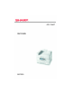
Introduction Congratulations on buying an Sharp color printer. Your new printer is designed with advanced features to give you clear, vibrant color prints and crisp black and white pages at high speed on a range of print media for the office.
> USB 2.
Additionally, the following optional features are available: > High Capacity Feeder (HCF) (1590 sheets) for loading a further sheets at a time to minimize operator intervention, or different paper stocks for letterhead stationery, alternative paper sizes or other print media: > Memory Expansion DIMM > Finisher for stapling or saddle stitching printer output > Punch unit (to extend Finisher functionality) > EFI Color Profiler Kit Sharp AR-C360P User’s Guide Introduction > 9
About this guide NOTE Images used in this manual may include optional features that your printer does not have installed. Also, they may omit features not essential to the description of a particular function. This manual is your user’s guide (check the web site, www.sharpusa.
These are paper documents that are packaged with the consumables and optional accessories. > Online Help: online information accessible from the printer driver and utility software Online usage This guide is intended to be read on screen using an Adobe Acrobat Reader. Use the navigation and viewing tools provided in Acrobat. You can access specific information in two ways: > In the list of bookmarks down the left hand side of your screen, click on the topic of interest to jump to the required topic.
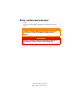
2. Choose which pages you wish to print: (a) [All pages], (1), for the entire manual. (b) [Current page], (2), for the page at which you are looking. 1 2 3 (c) 3. [Pages from] and [to], (3), for the range of pages you specify by entering their page numbers. Click on [OK].
Printer and paper overview Opening and closing the top cover To open the top cover, squeeze the top cover handle (1) to release the catch and raise the cover. 1 To close the top cover, push gently (1) until the cover stops midway and then push harder (2) to close the cover completely. Ensure that the cover is securely closed.
Identifying major components The major components of your printer are identified in the graphics below. 1. Paper holding arm 2. Top cover (face-down stacker) 3. MP Tray (multi-purpose tray) 4. Tray 1 side cover 5. Paper size label 6. Paper gauge 7. Tray 1 (paper tray) 8. Control panel 9.
10. Face-down stacker 11. Power (on/off) switch 12. Face-up stacker 13.
14. Interface unit 15. Network interface connector 16. Parallel interface connector 17. USB interface connector 18. Power connector 19.
20. Image drum cartridge and toner cartridge (Cyan) 21. Image drum cartridge and toner cartridge (Magenta) 22. Image drum cartridge and toner cartridge (Yellow) 23. Image drum cartridge and toner cartridge (Black) 24. Toner cartridge 25. Image drum cartridge 26. Fuser unit 27.
28. Belt unit 29. Drum basket handle 30.
31. High capacity Feeder (HCF) 3 trays 31 Software supplied CDs: > Printer Drivers Contains PCL and PS drivers, utilities and productivity software for the PCL driver. > Documentation Contains documentation in electronic form to describe how to use the printer for day-to-day tasks.
Paper recommendations Your printer will handle a variety of print media, including a range of paper weights and sizes, transparencies and envelopes. This section provides general advice on choice of media, and explains how to use each type. The best performance will be obtained when using standard weight 20 – 24 lb (75 – 90 g/m²) paper designed for use in copiers and laser printers.
Paper input and output information The following table relates paper parameters to input trays (Tray 1 to Tray 4 (numbering from the top) and MP Tray) and to output areas (Face-down stacker and Face-up stacker). TYPE SIZE WEIGHT Plain paper A3, A3 Nobi, A3 Wide, A4, A5, A6, B4, B5, Letter, Legal 13, Legal 13.5, Legal 14, Executive, Tabloid, Tabloid Extra 17 – 57 lb Custom W: 3.94 – 12.
TYPE SIZE WEIGHT Transparencies A4, Letter 0.
Trays and stackers Trays 1 to 4 Tray 1 is the standard blank paper input tray and can hold up to 530 sheets of 20 lb (75 g/m²) paper. Additional trays (via the High Capacity Feeder), to give a total of 4, can be added as an option to give a total tray capacity of 2120 sheets of 20 lb (75 g/m²) paper. If you have identical paper stock loaded in another tray (for example Tray 2 or the MP Tray), you can have the printer automatically switch to that other tray when the current tray runs out of paper.
stocks from 17 – 57 lb (64 – 216 g/m²). Pages printed in reading order (page 1 first) will be sorted in reading order (last page on top, facing down). Face-up stacker The face-up stacker should be opened and the tray extension pulled out when required for use. (With the face-up stacker either open or closed, the driver setting of Face Down will successfully direct prints to the Face-Down stacker.
Tray and stacker examples Loading Trays 1 to 4 Tray 1 is used in the following example. 1. Pull out the tray. 2. Press the paper rear stopper tab (1) and adjust the tab to the required paper size. 1 3. Fan the paper to be loaded then tap the edges of the stack on a flat surface to make it flush. 4. Load the paper (face down and top edge towards the right for letterhead paper), press the tab (2) on the paper guide and adjust the guides (3) for a snug fit to the paper.
To avoid paper jams: > Do not leave space between the paper and the guides and rear stopper. > Do not overfill the paper tray. Capacity depends on the paper type. > Do not load damaged paper. > Do not load paper of different sizes or types at the same time. 3 2 5. Gently push the tray back into the printer.
Using the MP Tray 1. Squeeze the handle (1) and open the multi-purpose tray. 1 2. Fold out the paper support section and swivel out the extension supports (2). 3 2 3. Adjust the paper guides (3) to the size of the paper being used.
4. Fan the paper to be loaded then tap the edges of the stack on a flat surface to make it flush. 5. Load the paper. > For single-sided printing on letterhead, load the paper into the multi-purpose tray with pre-printed side up and top edge into the printer. > For two-sided (duplex) printing on letterhead, load the paper with pre-printed side down and top edge away from the printer. > Envelopes should be loaded face-up with long edge into the printer. Do not select duplex printing on envelopes.
Using the stackers Face-down stacker When the face-up stacker (1) on the left side of the printer is closed (its normal position), paper is ejected to the face-down stacker on the top of the printer. 1 Face-up stacker The face-up exit path is used for heavy paper (cardstock etc.), envelopes, transparencies, and labels. 1. Open the stacker (1).
2. Flip out the paper support (2). 2 3. Swivel out the paper support extension (3).
Control panel The control panel can be swivelled to 90° (maximum) upwards from its base position (1) as required for ease of use.
Buttons and lights The parts of the control panel are identified and briefly explained below: 1. Shutdown/Restart button Hold down for more than 2 seconds for a soft shutdown. You can then press this button again for a restart or use the Power switch to turn off the printer completely. 2. Ready light On: indicates ready to print Flashing: indicates processing print data Off: indicates unable to receive data (offline) 3.
5. Up-arrow button Enters menu mode and enables upward movement through the displayed list of menu items 6. Down-arrow button Enters menu mode and enables downward movement through the displayed list of menu items 7. Back button Returns to the previous higher level menu item 8. Enter button Enters menu mode and selects the menu item highlighted in the display panel 9. Online button Switches between online (printer ready to receive data) and offline (printer not ready to receive data) 10.
Display Panel messages There are four types of display panel message: > Help information > Status information > Menu (functions) information > Configuration information The display panel messages, supplemented by the Help messages where appropriate, are intended to be self-explanatory. More information on typical messages is provided in “Appendix A – Display Panel Messages” on page 100 Help mode When an error has occurred, press the Help button. Information displays that will help you correct the error.
menus are available to the general user to make various settings that are used in the running of the printer. Administrator menu: accessed by pressing the Enter button for more than 2 seconds while turning on the printer power supply (including Restart). Available to administrator level users. Restricts the changes that general users can make via the user menus.
Using the menus NOTE Menu details are given in “Appendix B – Menu system” on page 102 for reference. The Enter, Up-arrow, Down-arrow and Back buttons are used to move through the printer menus. You can adjust settings (e.g. set the paper size for Tray 1) or view information (e.g. how much is left of a selected consumable). Many of these menu settings can be, and often are, overridden by settings in the Windows printer drivers.
Getting started This section provides information to help you get started with using your printer.
> above your printer: 70cm 28in Turning Off/On Turning Off 1. Hold down the Shutdown/Restart button (1) on the control panel for more than 2 seconds to start the shutdown process.
2. When the display panel shows that you can either turn off or restart the printer, use the On/Off switch to turn off the printer. Please wait as this may take a short time. Turning On NOTE If the display panel shows that you can either turn off or restart the printer, press Shutdown/Restart to turn on the printer. 1. If the printer is turned off (no power), use the On/Off switch to turn on the printer. Please wait as this may take a short time.
Checking current settings Carry out the following steps to generate a Configuration report (Menu Map) to confirm that your printer is correctly configured. 1. Ensure that there is Letter paper in Tray 1 (to be used in this operation). 2. Ensure that the display panel indicates that the printer is ready to print. 3. Press the Up-arrow or Down-arrow buttons repeatedly until Print Pages is highlighted. 4. Press the Enter button to select Print Pages. 5.
> Ethernet – For network cable connection. NOTE Interface cables are not supplied with your printer. Connecting the parallel interface 1. Turn off the printer and the computer. 2. Connect a parallel cable between the printer and computer. 3. Turn on the printer and then the computer. Connecting the USB interface Do not connect the USB cable at this time. You will be instructed when to connect the USB cable when you run the Drivers CD.
2. Remove the protective cover from the network connector on the printer. 3. Connect an Ethernet cable between the printer and an Ethernet hub.
4. Turn on the printer and then the computer. If your printer is to be installed as a network printer, please refer to the relevant section in the Software Installation Guide and Configuration Guide for further details on how to configure the network connection before installing the printer drivers. NOTE Administrator’s authority is required when installing a network connection. Using the Drivers CD For instructions on installing the drivers and other software, refer to the Software Installation booklet.
Operation Using the printer For full details of how to use the printer and any optional accessories to print jobs efficiently and effectively, please refer to the Printing Guide.
Consumables and maintenance This section explains how to replace consumable and maintenance items when due. As a guide, the life expectancy of these items is: > Toner — 15,000 Letter pages at 5% coverage. The printer is shipped with sufficient toner for 7,500 Letter pages in the print cartridges of which 1 – 2,000 Letter pages of toner are used to charge the image drum.
Consumable item order information ITEM LIFE ORDER NUMBER Toner, Black 15,000 Letter pages @ 5% AR-C36TBU Toner, Cyan 15,000 Letter pages @ 5% AR-C36TCU Toner, Magenta 15,000 Letter pages @ 5% AR-C36TMU Toner, Yellow 15,000 Letter pages @ 5% AR-C36TYU Image drum, Black 42,000 Letter pages continuous print AR-C36BDR Image drum, Cyan 42,000 Letter pages continuous print AR-C36CDR Image drum, Magenta 42,000 Letter pages continuous print AR-C36MDR Image drum, Yellow 42,000 Letter pages c
Replacing consumables/maintenance items Each consumable or maintenance item comes complete with its own installation details which give full instructions on replacement. You are advised to follow these instructions carefully. CAUTION! Only use genuine Sharp consumables to ensure the best quality and performance from your hardware. Non-Sharp products may damage your printer’s performance and invalidate your warranty.
2. With an LED lens cleaner or soft cloth, gently wipe each of the four heads (1). Move the cleaner as shown, using a clean section of the cleaner with each pass. Be careful not to damage the guards (2). 1 3. Close the top cover.
Cleaning the paper feed rollers Clean the paper feed rollers if paper jams frequently occur. 1. Remove items like a wrist watch or bracelet then use the Shutdown/Restart button followed by the On/Off switch to turn the printer off. 2. Open Tray 1 side cover and pull out the paper guide plate (1).
3. Remove Tray 1 completely from the printer. 4. Gaining access through the gap left by Tray 1, wipe the 3 paper feed rollers (2) with a soft cloth lightly moistened with water. 2 5. Replace Tray 1.
6. Return the paper guide plate to its original position and close Tray 1 side cover. 7. Turn on the printer.
Cleaning the printer casing 1. Turn the printer off by using the Shutdown/Restart button followed by the On/Off switch. 2. Wipe the printer surface with a soft cloth moistened sparingly with water or neutral detergent. 3. Use a soft dry cloth to dry the printer surface.
4. Turn on the printer.
Emptying the punch chip box (Punch unit optional accessory) When the display panel indicates that the punch chip box is full, empty the box as follows: 1. Operate the Finisher lever and move the Finisher away from the printer. 2. Pull out the punch chip box, being careful to keep it level so as not to spill any chips.
3. Discard the chips in an appropriate place. 4. Replace the punch chip box carefully into the Finisher.
5. Check that the punch chip box has been replaced correctly then move the Finisher back into position, being careful not to trap your fingers.
Optional accessories This section describes optional accessory equipment for your printer.
Installing accessories Each accessory (apart from the Finisher and MFP Upgrade Kit) comes complete with its own documentation which gives full instructions on installation. You are advised to follow these instructions carefully. After installation, print out a Menu Map (Configuration document) to check that the installation has been successful. For the following accessories, you have to make the appropriate setting in your printer driver(s): > Finisher Refer to the Printing Guide for driver setting details.
Troubleshooting This section provides information to help you deal with problems that may arise when using the printer. The following paragraphs describe actions to take in the event of a paper jam and how to deal with unsatisfactory print results. Display panel messages about paper jams and relevant actions are given in this section while a list of other typical messages and suggested responses is given in “Appendix A – Display Panel Messages” on page 100.
2. Holding it by the tab (2), turn the paper guide outward. 2 3. Carefully remove the jammed paper. 4. Put the paper guide back into position and close Tray 1 side cover.
Open cover, paper jam, side cover 1. If the MP Tray is open, close it so that the side cover (1) is visible. 1 2. Pull the release lever (2) and pull open the side cover.
3. Carefully remove the jammed paper. 4. Close the side cover.
Open cover, paper jam, top cover 1. Squeeze the top cover handle (1) and open the top cover. 1 WARNING! Be careful not to touch the fuser unit which is hot after printing. 2. Squeeze the basket handle (2) and raise the drum basket.
3. Carefully remove any paper on the belt. 4. If paper is jammed in the fuser unit, push the lock lever (3) in the direction shown to release the unit. WARNING! Be careful not to touch the fuser unit which may be hot after printing. If the fuser unit is hot, wait until it cools before attempting to remove any jammed paper. Holding the fuser unit (4) by the handle, lift it out of the printer and place it on a flat surface.
5. Pull up the jam release levers (5) and remove the jammed paper. 5 6. Carefully replace the fuser unit into the printer and turn the lock lever (6) in the direction shown to lock the fuser unit.
7. If paper is jammed near the paper exit, open the face-up stacker (7). 7 8. Open the side cover (paper exit) (8) and remove the jammed paper.
9. 10. Close the side cover (paper exit) and then the face-up stacker. Return the image drum basket (9) into position and check it is locked.
11. Close the top cover and ensure it is latched. Paper jams – duplex unit Check duplex unit, paper jam 1. If a Finisher unit is attached to your printer, operate the lever (1) of the Inverter unit to separate the Inverter from the printer.
2. Operate the duplex cover release button (2) and open the cover. 2 3. Carefully remove any jammed paper.
4. Operate the levers (3) and pull out the duplex unit. 3 3 5. Holding the front top cover by the grip (4), push it gently inwards and raise it.
6. Remove any jammed paper. 7. In similar manner, check for and clear any paper jammed under the rear top cover.
8. Replace the two top covers. 9. Raise the front cover of the duplex unit.
10. Push the duplex unit back into position. 11. If you detached a Finisher unit to gain access to the duplex unit, replace the Finisher unit.
Paper jams – Finisher (optional accessory) Check Finisher, paper jam/paper remains Use the Help button on the printer control panel to check the number displayed. You will need this to be able to clear the paper jam. The following paragraphs explain what to do for each of the indicated numeric codes. 591, 592, 593, 599/ 643, 645 (paper jam around Finisher) 1. Remove any paper at the Finisher paper exit.
2. Operate the Finisher lever (1) and move the Finisher away from the Inverter. 1 3. Open the Finisher top cover.
4. Carefully remove any jammed paper. 5. Close the Finisher top cover.
6. Move the Finisher back into position and connect it to the Inverter. 594, 597, 598/ 644, 646 (paper jam in Finisher) 1. Operate the Finisher lever (1) and move the Finisher away from the Inverter.
2. Open the Finisher front cover (2). 2 3. Continue to turn the lower knob (3) clockwise until any jammed paper is completely ejected.
4. Remove the ejected paper. 5. Close the Finisher front cover.
6. Open the Finisher right side cover. 7. Carefully remove any jammed paper.
8. Close the Finisher right side cover. 9. Move the Finisher back into position and connect it to the Inverter.
590 (paper jam in Finisher/Punch unit) 1. Operate the Finisher lever (1) and move the Finisher away from the Inverter. 1 2. Move the tab (2) on the right side of the Finisher to align it with the mark (3).
3. Open the Finisher top cover. 4. Carefully remove any jammed paper. 5. Close the Finisher top cover.
6. Move the Finisher back into position and connect it to the Inverter. Check Inverter, paper jam 1. Operate the Finisher lever (1) and move the Finisher away from the Inverter.
2. Squeeze the recessed handle (2) and open the left side cover of the Inverter. 2 3. Carefully remove any jammed paper.
4. Close the Inverter left side cover. 5. Move the Finisher back into position and connect it to the Inverter.
6. Operate the Inverter lever (3) and separate the Inverter from the printer. 3 7. Open the right side door (4) of the Inverter.
8. Remove any jammed paper. 9. Close the right side door.
10. Move the Finisher and Inverter back into position and connect to the printer. Avoiding paper jams The following table summarizes possible causes of paper jams and suggests ways of avoiding them. POSSIBLE CAUSE SUGGESTED REMEDY The printer is not level. Place the printer on a steady, level surface. Your print media is too light or too heavy. Use appropriate media. Your print media is damp or charged with static electricity.
POSSIBLE CAUSE SUGGESTED REMEDY Your printer feed roller is dirty. Wipe the roller with a cloth moistened with water. Your printer feed rollers are wearing out. Replace the feed rollers. The media weight or type have been wrongly set. Select the correct printer menu settings for [Media Weight] and [Media Type].
Dealing with unsatisfactory printing SYMPTOMS POSSIBLE CAUSES STEPS TO TAKE Vertical white lines can be seen on the printed page. The LED head is dirty. Wipe the LED head with a LED lens cleaner or with a soft cloth. The toner is low. Replace the toner cartridge. Foreign materials may be present in the image drum. Replace the image drum cartridge. Light-shielding film of the image drum cartridge is dirty. Wipe the film with a LED lens cleaner or with a soft cloth. The LED head is dirty.
SYMPTOMS POSSIBLE CAUSES STEPS TO TAKE Vertical lines appear. The image drum cartridge is damaged. Replace the image drum cartridge. The toner is low. Replace the toner cartridge. When the interval is about 94mm (4in), the image drum (the green tube) is damaged or dirty. Wipe it lightly with a soft cloth. Replace the image drum cartridge when it is damaged. When the interval is about 42mm (1.5in), there may be foreign particles in the image drum cartridge.
Staple jams – Finisher (optional accessory) Check Finisher, Staple Jam When the display indicates a staple jam has occurred, clear the jam as follows: 1. Open the Finisher front cover. 2. Turn the knob in the direction indicated until the colored indicator appears.
3. Remove any paper that awaits stapling in the paper ejection area. 4. Pull out the staple unit.
5. Turn the knob in the direction indicated to move the stapler to the front. 6. Grip both sides of the staple cartridge, pull it up and remove it. 7. Raise the staple cartridge gate.
8. Remove all staples that are emerging from the staple case. 9. Return the staple cartridge gate to its original position. 10. Replace the staple cartridge.
11. Ensure that the staple cartridge is securely installed back into the staple unit then push the staple unit fully home. 12. Close the Finisher front cover, being careful not to trap your fingers.
Specifications ITEM SPECIFICATION Dimensions 25.8x24.4x18.2 in (WxDxH) 655x620x462 mm (WxDxH) Weight Without options, 152 lb (68 kg) Print speeds 36 ppm color; 40 ppm monochrome 20 – 28 lb paper Resolution 1200 x 1200 dpi Emulations PCL 5c, PCL XL 2.1, PS Memory 1 GB (max.
ITEM Noise level SPECIFICATION Operating: 53dBA maximum Standby: 40dBA maximum Power save: 40dBA maximum after 30 mins background level Sharp AR-C360P User’s Guide Specifications > 99
Appendix A – Display Panel Messages The display panel messages are intended to be self-explanatory. Representative messages are given as examples below. MESSAGE COMMENT Ready to Print Your printer is online and ready to print. Printing tttttt Your printer is printing and paper is currently being fed from tttttt, where tttttt identifies a tray. tttttt Near End The paper supply in the tray identified by tttttt will run out soon. cccccc Toner Low The remaining toner of color cccccc is running low.
MESSAGE COMMENT Open Cover Paper Remains tttttt Please see HELP for details Additional paper has been detected after a paper jam has been cleared. Open tttttt side cover to check for additional paper. Check Image Drum cccccc Please see HELP for details Check that the image drum of color cccccc is correctly installed. You can access help details by pressing the HELP button. You can access help details by pressing the HELP button.
Appendix B – Menu system The top-level Functions menus are: > Configuration > Print Pages > Suspend Printing > Resume Printing > Print Secure Job > Menus > Shutdown > Admin Setup > Calibration > Print Statistics The other special top-level menu is: > System Maintenance The following tables summarise the Configuration, Print Pages, Print Secure Job and Menus menu trees and provide some usage examples. The menu trees are given to the lowest menu item level.
Configuration Print Page Count ITEM VALUE DESCRIPTION Color Page nnnnnn Displays number of color printed pages converted to Letter equivalent. Monochrome Page nnnnnn Displays number of monochrome printed pages converted to Letter equivalent. Traym nnnnnn Displays total printed pages from Traym, where m is in range 1 to 4. MP Tray nnnnnn Displays total printed pages from MP tray. ITEM VALUE DESCRIPTION Staple nnnnnn Displays total pages stapled.
Supplies Life ITEM VALUE DESCRIPTION xxxx Drum Remaining nnn% Displays the remaining life span of the xxxx drum as a percentage where xxxx can be Cyan, Magenta, Yellow, Black. Belt Remaining nnn% Displays the remaining life span of the belt unit as a percentage. Fuser Remaining nnn% Displays the remaining life span of the fuser unit as a percentage. xxxx Toner (n.nK) Remaining nnn% Displays the remaining life span of xxxx toner as a percentage, where xxxx can be Cyan, Magenta, Yellow, Black.
Paper Size in Tray ITEM VALUE DESCRIPTION Traym where m is in range 1 to 4 Executive Letter Short Edge Letter Long Edge Legal 14 Legal 13.5 Tabloid Tabloid Extra Legal 13 A6 A5 A4 Short Edge A4 Long Edge A3 A3 Nobi A3 Wide B5 Short Edge B5 Long Edge B4 Postcard Double Postcard Custom Displays detected paper size of Traym. Similar to values for Traym Displays detected paper size of the MP Tray. ITEM VALUE DESCRIPTION Serial Number xxxxxxxxxxxxxxx Displays serial no. of the printer.
ITEM VALUE DESCRIPTION Total Memory xx MB Displays total RAM memory installed in the printer. Same as Total Memory of Menu Map. HDD xx.xx GB [Fxx] Displays size of hard disk and file system version. Same as HDD of Menu Map. Configuration example – monochrome pages printed To display the total monochrome pages printed so far (remembering that a duplex page counts as two pages): 1. Ensure that the display panel indicates that the printer is ready to print. 2.
Print Pages ITEM VALUE DESCRIPTION PS Test Page Execute Prints the PostScript sample page. Configuration Execute Prints printer configuration details. Job Log Execute Prints EFI job log details. Color Charts (disk only) Execute Prints colour charts. PS Font List Execute Prints PostScript font list. PCL Font List Execute Prints PCL emulation font list. Demo Page Execute Prints a demo page. Usage Report Execute Prints usage report. Statistics Log Execute Prints job log details.
Print Information example – demonstration page To print a printer demo page to demonstrate how your printer prints: 1. Ensure that the display panel indicates that the printer is ready to print. 2. Enter menu mode by pressing either the Up-arrow or Down-arrow button and press them repeatedly until the Print Pages menu is highlighted. 3. Press the Enter button to select this menu. 4. Press the Up-arrow or Down-arrow buttons repeatedly until Demo page is highlighted. 5.
Print Secure Job ITEM VALUE DESCRIPTION Enter Password nnnn Enter a password to use secure printing. Not Found Secure Job Print Delete Use a secure printing job (Secure Job) or a job Stored to HDD when printing. When you print a Secure document, it is deleted from the HDD. When you print a document Stored to HDD, it prints and remains stored on the HDD until you manually delete it. Not Found: (no jobs) is indicated when there is no output file.
ITEM VALUE DESCRIPTION Traym Config, where m is in range 1 to 4 Paper Size Tray Size Custom Sets paper in Traym. (similar arrangement for all trays) X Dimension 3.9 – 8.3 (A) – 8.5 (L) – 12.9 inch 100 – 210 (A) – 216 (L) – 328 mm Sets Custom paper width for Traym. Sets for the direction perpendicular to the direction of paper movement. Y Dimension 5.8 – 11 (L) – 11.7 (A) – 18 inch 148 – 279 (L) – 297 (A) – 457 mm Sets Custom paper length for Traym. Sets for the same direction as paper movement.
ITEM VALUE Traym Config, where m is in range 1 to 4 Media Weight Auto Light Medium Light Medium Medium Heavy Heavy Ultra Heavy 1 Ultra Heavy 2 Ultra Heavy 3 Sets media weight for Traym. A3 Nobi Paper A3 Nobi A3 Wide Tabloid Extra The printer detects A3 Nobi, A3 Wide and Tabloid Extra sizes as the same. Use this setting to tell the printer which of the three sizes is loaded in Traym. Legal 14 Paper Legal 14 Legal 13.5 Sets the length of the legal paper in Traym. Change this to Legal 13.
ITEM VALUE DESCRIPTION MP Tray Config Paper Size A3 Nobi A3 Wide A3 A4 Sht Edge A4 Long Edge (A) A5 A6 B4 B5 Short Edge B5 Long Edge Legal 14 Legal 13.5 Tabloid Extra Tabloid Letter Sht Edge Letter Long Edge (L) Executive Custom Com-9 Envelope Com-10 Envelope Monarch Envelope DL Envelope Landscape Postcard Double postcard C5 C4 Envelope Index Card Sets paper size for MP Tray. X Dimension 3 – 8.3 (A) – 8.5 (L) – 12.9 inch 76 – 210 (A) – 216 (L) – 328 mm Sets Custom paper width for the MP Tray.
ITEM VALUE DESCRIPTION MP Tray Config Media Type Plain Letterhead Transparency Labels Bond Recycled Card stock Rough Glossy Envelope User Type1 User Type2 User Type3 User Type4 User Type5 Sets the media type for MP Tray. Media Weight Auto Light Medium Light Medium Medium Heavy Heavy Ultra Heavy 1 Ultra Heavy 2 Ultra Heavy 3 Sets the media weight for MP Tray. Tray Usage Normal Tray Tray selection/switching uses this tray as the normal tray.
System Adjust ITEM VALUE DESCRIPTION Power Save Time 5 min 15 min 30 min 60 min 240 min Sets the period after which power save mode starts. Clearable Warning Online Job When Online is selected, you must manually clear the warning by pressing the Online button. Change to Job if you wish the message to automatically clear when a new print job is received. Auto Continue ON OFF Sets whether the printer is automatically recovered when Memory Overflow or Tray Request occurs.
ITEM VALUE DESCRIPTION Low Toner Continue Stop Sets the printing operation when insufficient toner is detected. Continue: the printer can continue printing while remaining online. Stop: the printer stops printing and goes offline. Jam Recovery ON OFF ON: continues printing the job, including any jammed pages, once the jam has been cleared. OFF: Cancels a job including the page currently jammed. Print Position Adjust X Adjust 0.00 +0.25 – +2.00 -2.00 – -0.25 mm 0.00 +0.01 – +0.08 -0.08 – -0.
ITEM VALUE Print Position Adjust Duplex X Adjust DESCRIPTION 0.00 +0.25 – +2.00 -2.00 – -0.25 mm 0.00 +0.01 – +0.08 -0.08 – -0.01in Duplex Y Adjust 0.00 +0.25 – +2.00 -2.00 – -0.25 mm 0.00 +0.01 – +0.08 -0.08 – -0.01 in During the flip-side printing of duplex printing, adjusts the location of the whole printing image (0.25 mm, 0.01in interval) perpendicular to the direction of paper movement (i.e. horizontally).
ITEM VALUE DESCRIPTION Paper Black Setting 0 +1 – +2 -2 – -1 Used for micro adjustment when very visible faded print results or light specks (or streaks) result when printing in Plain Paper/Black setting. Decrease the value if light specks (or streaks) or snow flake like printing results in high density print areas. Paper Color Setting 0 +1 – +2 -2 – -1 Used for micro adjustment when very visible faded print results or light specks (or streaks) result when printing in Plain Paper/Color setting.
Menus example 1 – Tray 1 transparencies To print on transparencies (accommodated in Tray1): 1. Ensure that the display panel indicates that the printer is ready to print. 2. Enter menu mode by pressing either the Up-arrow or Down-arrow button and press them repeatedly until the Menus menu is highlighted. 3. Press the Enter button to select this menu. 4. Press the Up-arrow or Down-arrow buttons repeatedly until Tray Configuration is highlighted. 5. Press the Enter button to select this Item. 6.
Menus example 2 – MP Tray paper size To set paper size in the MP Tray: 1. Ensure that the display panel indicates that the printer is ready to print. 2. Enter menu mode by pressing either the Up-arrow or Down-arrow button and press them repeatedly until the Menus menu is highlighted. 3. Press the Enter button to select this menu. 4. Press the Up-arrow or Down-arrow buttons repeatedly until Tray Configuration is highlighted. 5. Press the Enter button to select this Item. 6.
INDEX A USB40, 41 M accessories57 installing58 order details57 arrow buttons33 maintenance items order details46 replacing45 menu Admin Setup102 Calibration102 Configuration102, 103 Menus102, 109 Print Information107 Print Pages102 Print Secure Job102, 109 Print Statistics102 Resume Printing102 Shutdown102 Suspend Printing102 System Maintenance102 using36 B back button33 C cancel button33 cleaning feed rollers49 LED heads47 printer casing52 clearing paper jams59 staple jams93 consumables order details
software19 specifications98 T troubleshooting59 turning off38 on39 U unsatisfactory printing91 user’s guide printing11 Sharp AR-C360P User’s Guide Index > 121