[00]COVER.fm 1 ページ 2004年4月27日 火曜日 午後6時32分 CODE : 00ZARF14//A1E AR-F14 DIGITAL COPIER MULTIFUNCTIONAL SYSTEM OPTIONS FINISHER PUNCH UNIT MODEL AR-F14 AR-PN1 CONTENTS [1] INTRODUCTION . . . . . . . . . . . . . . . . . . . . . . . . . . . . . . . . . . . . 1 - 1 [2] EXTERNAL VIEWS AND INTERNAL STRUCTURES . . . . . . . 2 - 1 [3] UNPACKING AND INSTALLATION . . . . . . . . . . . . . . . . . . . . . . 3 - 1 [4] OPERATIONAL DESCRIPTION . . . . . . . . . . . . . . . . . . . . . . . .
[co]CONTENTS.fm 1 ページ 2004年4月19日 月曜日 午後1時43分 CONTENTS [1] INTRODUCTION [6] MAINTENANCE 1. Product outline . . . . . . . . . . . . . . . . . . . . . . . . . . . . . . . 1-1 1. Maintenance System Table . . . . . . . . . . . . . . . . . . . . . . 6-1 2. Configuration . . . . . . . . . . . . . . . . . . . . . . . . . . . . . . . . 1-1 2. Discarding punch waste (when a punch unit is installed) . . 6-1 3. Specifications . . . . . . . . . . . . . . . . . . . . . . . . . . . . . . . . 1-1 4.
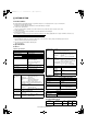
[01]INTRODUCTION.fm 1 ページ 2004年4月28日 水曜日 午後4時59分 [1] INTRODUCTION 1. Product outline This unit is installed to the following machines to perform the after-process of output paper from a copier, or a fax machine. 1) Employment of the through-type stapler Employment of the through-type stapler allows to make saddle stitch by one stapler. 2) 3 kinds of auto staple functions There are 3 staple positions available.
[02]EXTERNALVIEWS.fm 1 ページ 2004年4月19日 月曜日 午後1時36分 [2] EXTERNAL VIEWS AND INTERNAL STRUCTURES 1. External view [1] [2] [3] [4] [5] [6] B. Saddle section Stapler compiler Top cover Stapler section Front cover Saddle stitch tray Offset tray [1] [1] [2] [3] [4] [5] [6] A. Finisher section [3] [2] [3] [4] [5] Fig. F01-301-02 2.
[02]EXTERNALVIEWS.fm 2 ページ 2004年4月19日 月曜日 午後1時36分 3. Finisher and saddle section Code A.
[02]EXTERNALVIEWS.fm 3 ページ 2004年4月19日 月曜日 午後1時36分 4. Interface transport section B. Motor FPNM FJOS FJM FJES FPSM FJCS A. Sensor Code / Brevity Code Name Active condition Remark FJOS Interface transport unit paper exit sensor Paper detection: [L] FJES Interface transport unit paper entry sensor Paper detection: [L] FJCS Interface transport unit cover sensor Cover open: [L] Fig. F05-202-02 Code B.
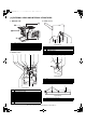
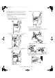
[03]UNPACKINGANDINSTALLATION.fm 1 ページ 2004年4月27日 火曜日 午後7時4分 [3] UNPACKING AND INSTALLATION 1.AR-F14 1) Remove the exit tray cover. •If the copier is equipped with an exit tray cover: Remove the screw and then remove the exit tray cover as shown in the illustration. •For installation of AR-F14, an optional stand (small stand or large stand) must have been installed. •When adjusting the height of the finisher, be sure to perform step15) with the finisher placed on the packing box.
[03]UNPACKINGANDINSTALLATION.fm 2 ページ 2004年4月27日 火曜日 午後7時4分 4) Remove the right cabinet. <1>Open the bypass tray. <2>Open the right door. <3>Remove the two screws and then remove the right cabinet. 5) Remove the copier second exit unit. <1>Remove the connector of the copier second exit unit from the copier. <2>Remove the four screws and then remove the copier second exit unit. 6) Attach the supplied F14 second exit unit.
[03]UNPACKINGANDINSTALLATION.fm 3 ページ 2004年4月27日 火曜日 午後7時4分 10) Attach the docking unit. Insert docking mounting angel F and docking mounting angel R that have been attached to the copier, into the holes of the docking unit. 11) Secure the docking unit. <1>Use two screws A (M4 x 10) to secure the unit to the copier. <2>Then use the screw that has been remove in step2) to secure the docking unit. 12) Attach the paper holder arm to the transport unit.
[03]UNPACKINGANDINSTALLATION.fm 4 ページ 2004年4月27日 火曜日 午後7時4分 •If the copier is equipped with a small stand and three paper drawers, proceed to step16). •If the copier is equipped with a large stand and two paper drawers or a small stand and four paper drawers, you must change the height of the finisher. In this case, be sure to perform step15) with the finisher placed on the packing box. <4>Reattach the cover and secure it with the screw.
[03]UNPACKINGANDINSTALLATION.fm 5 ページ 2004年4月27日 火曜日 午後7時4分 18) Install the stapler unit into the finisher. <1>Remove the packing the tape (two pieces) from the locations shown in the illustration. 20) Check and adjust the height of the finisher. Bring the finisher close to the copier and check that the guide pin is inserted smoothly into the connecting hole of the finisher. If the guide pin should not be inserted smoothly, adjust as follows.
[03]UNPACKINGANDINSTALLATION.fm 6 ページ 2004年4月27日 火曜日 午後7時4分 <2>If the gap between the copier and the finisher is not uniform at the upper and lower parts, remove the caps from the front side and the rear side of the finisher stand with a flat-blade screwdriver or the like. Then, remove the screws of the front and rear subcovers (one screw for each) and then remove the subcovers.
[03]UNPACKINGANDINSTALLATION.fm 7 ページ 2004年4月27日 火曜日 午後7時4分 2. AR-PN1 <1> Then remove the power plug of the main unit from the outlet. <2> Remove the connector of the finisher. For installation of AR-PN1A/PN1B/PN1C/PN1D, a saddle stitch finisher (AR-F14) must have been installed. 2) Remove the front cabinet and the rear cabinet from the finisher. <1> Open the front door of the finisher and remove the jam handling dial. Parts included Jam handling dial Harness A (purple): 1 pc.
[03]UNPACKINGANDINSTALLATION.fm 8 ページ 2004年4月27日 火曜日 午後7時4分 3) Remove the top cover. <1> Remove the four top cover securing screws and remove the top cover. <3> Remove the boss on the upper side of the paper entry PG. Screw Top cover <4> Remove the boss on the lower side of the paper entry PG with a straight-slot screwdriver. <2> Remove the four pawls from the top cover and separate the cover into the upper and lower portions. Reuse the upper portion.
[03]UNPACKINGANDINSTALLATION.fm 9 ページ 2004年4月27日 火曜日 午後7時4分 5) Attach the punch module. <1>Insert the two bosses of the punch unit into the boss holes of the finisher and fix the punch module using three screws. Note: For the screws, use a supplied screw and the two screws that have been removed in step 4). 7) Reattach the covers that have been removed. <1>Hang the two pawls of the top cover and secure them using the two screws.
[03]UNPACKINGANDINSTALLATION.fm 10 ページ 2004年4月27日 火曜日 午後7時15分 <4>Reattach the jam handling dial and close the front cover. 9) Connect the connector to the stand/paper drawer and connect the AC cord of the power supply unit to the main unit of the printer. <1>Connect the connector of the relay harness of the finisher to the stand/paper drawer and tighten the screws of the connector.10) Paste the label. (Paste it only if the scanner module is installed.
[04]OPERATIONALDESCRIPTION.fm 1 ページ 2004年4月19日 月曜日 午後1時37分 [4] OPERATIONAL DESCRIPTION 1. Basic Operations A. Specifications The finisher serves to deliver sheets coming from its host machine. The mode of delivery may be non-sort stack, job offset*, or staple delivery. The saddle unit built into the finisher is used to fold a stack of sheets coming from the finisher unit in half for delivery.
[04]OPERATIONALDESCRIPTION.fm 2 ページ 2004年4月19日 月曜日 午後1時37分 C. Inputs to and Outputs from the Finisher Controller PCB •Outputs from the Finisher Controller PCB (1/2) Finisher controller PCB •Inputs to the Finisher Controller PCB (1/2) Finisher controller PCB CN44-3 -1 -2 Inlet sensor CN43-1 -3 -2 +24 V Binding clutch -1 CN42-3 CN16-10 +5 V -1 -12 ENT_S -11 -2 When the sensor detects paper, ‘1’ .
[04]OPERATIONALDESCRIPTION.fm 3 ページ 2004年4月19日 月曜日 午後1時37分 •Inputs to and Outputs from the Finisher Controller (1/2) Stapler unit Finisher controller PCB Slide home position sensor +5 V SHPS •Inputs to and Outputs from the Punch Controller PCB CN72-5 CN72A-5 Punch controller PCB When the stapler is at home position, ‘1’. CN72A-5 CN11-3 SLID_HP XXXX J2008-3 -1 -2 Punch home position sensor Staple home position sensor +5 V STHPS CN72-4 Staple empty sensor SPS D.
[04]OPERATIONALDESCRIPTION.fm 4 ページ 2004年4月19日 月曜日 午後1時37分 2. Feed/Drive System b.Job Offset A. Outline The machine performs the following in response to the commands coming from its host machine on the sheets arriving from the host machine for delivery: simple stacking, job offset, and stapling or folding (in two). If a punch unit (option) is installed, the sheets are pouched and delivered to the delivery tray.
[04]OPERATIONALDESCRIPTION.fm 5 ページ 2004年4月19日 月曜日 午後1時37分 d.Saddle Delivery The machine deposits a stack of sheets on the processing tray, staples it (middle 2-point), and then moves it to the saddle unit. The saddle unit folds the stack in two, and delivers it to the bind tray.
[04]OPERATIONALDESCRIPTION.fm 6 ページ 2004年4月19日 月曜日 午後1時37分 Aligning plate (rear) home position sensor (RJHPS) Aligning plate (rear) Inlet paper detect signal ENT_P Fold position paper detect signal BIND_P Finisher controller PCB Light-shielding plate Alignment plate (front) motor (FFJM) Alignment plate (rear) motor (FRJM) Aligning plate (front) ES (Front) Light-shielding plate Paper Aligning plate (front) home position sensor (FJHPS) Fig.
[04]OPERATIONALDESCRIPTION.fm 7 ページ 2004年4月19日 月曜日 午後1時37分 3. Stapling Operation Offsetting in the backward direction Aligning plate (rear) A.Outline Sheet to be offset Tray Aligning plate (front) Staple operation is performed to staple a specified sheets of paper using a stapler unit. The stapling position depends on the staple mode and paper size.
[04]OPERATIONALDESCRIPTION.fm 8 ページ 2004年4月19日 月曜日 午後1時37分 B.Stapling Operation C.Delivery Operation after Stapling When stacking and alignment of paper on the processing tray are complete, the finisher controller PCB drives the paddle motor (FPM) in the reverse direction and lowers the swing guide. When the swing guide descends, the paper stack is sandwiched between the upper and lower stack delivery rollers.
[04]OPERATIONALDESCRIPTION.fm 9 ページ 2004年4月19日 月曜日 午後1時37分 D.Stapler Unit (1)Stapler Movement Controller The staple/fold motor (FFSM) is used to perform stapling operation. This motor rotates the cam one turn for stapling. The home position of this cam is detected by the staple home position sensor (STHPS). The staple/fold motor is rotated in the forward or reverse direction under the control of the macro computer (IC13) on the finisher controller PCB.
[04]OPERATIONALDESCRIPTION.fm 10 ページ 2004年4月19日 月曜日 午後1時37分 4. Delivery Tray Operation d.Middle 2-point stapling (bind mode) The stapler waits at the back. The stapler moves to and returns from the stapling position for each stapling operation. The stapler first staples a paper stack at the rear stapling position and then staples it at the front stapling position. Standby position Stapler Stapling position Stopper Feed direction Stapling position Fig.
[04]OPERATIONALDESCRIPTION.fm 11 ページ 2004年4月19日 月曜日 午後1時37分 5. Saddle Unit b.Stitching A.Basic Operations (1)Outline The machine stitches a stack of sheets (middle 2-point), then folds the stack in two in the finisher. These operations are controlled by the finisher controller PCB. The finisher controller PCB is controlled by the commands from the host machine. When the center of the paper stack (stitching position) reaches the stapler's staple position, the stapler stitches the paper stack.
[04]OPERATIONALDESCRIPTION.fm 12 ページ 2004年4月19日 月曜日 午後1時37分 d.Folding/delivery D.Stack Feed System The paper pushing plate pushes in the center of the paper stack to feed it toward the paper fold rollers. Then, the paper fold rollers and bind delivery rollers deliver the paper stack to the bind tray. (1)Outline The stack feed system feeds the stitched paper stack to the folding position. When stitching is complete, the feed motor (FFM) rotates, causing the stack feed roller (upper) to descend.
[04]OPERATIONALDESCRIPTION.fm 13 ページ 2004年4月19日 月曜日 午後1時37分 (2)Paper Folding Paper is folded using paper fold rollers and a paper pushing plate. Almost concurrently with the start of roller rotation, the paper pushing plate starts operating to push the paper stack into the gap between the paper fold rollers. When the paper stack is fed about 10 mm with the rotation of the paper fold rollers, the paper pushing plate returns to the home position.
午後1時37分 (1)Outline The puncher unit is an option, and is designed for installation to the pickup assembly of the finisher. The puncher unit is not equipped with a paper feeding mechanism, and the sheets from the host machine move through the puncher unit and then the feed system of the finisher. When the trailing edge of a sheet from the host machine reaches the puncher unit, the sheet is stopped once, and the punch shaft is rotated to punch a hole along the trailing edge.
[04]OPERATIONALDESCRIPTION.fm 15 ページ 2004年4月19日 月曜日 午後1時37分 (2)Punching Operation 1) A hole is made along the trailing edge of the 1st sheet. The hole puncher is driven by the punch motor (FPNM). The home position for the hole puncher is detected by the punch home position sensor (XXXX). The punch unit comes in four types, selected to suit the country of installation: 2-hole (Puncher Unit-J1), 2- and 3-hole (Puncher Unit-K1), or two types of 4-hole (Puncher Unit-G1, Puncher Unit-H1).
[04]OPERATIONALDESCRIPTION.fm 16 ページ 2004年4月19日 月曜日 午後1時37分 (3)Horizontal Registration Operation The horizontal registration drive for the punch slide unit is provided by the horizontal registration motor (FPSM). The home position of the punch slide unit is detected by the horizontal registration home position sensor (PSHPS).
[04]OPERATIONALDESCRIPTION.fm 17 ページ 2004年4月19日 月曜日 午後1時37分 (1)Inlet Sensor Delay Jam (1011) The inlet sensor does not detect paper approximately 1.5 sec after the host machine generates the delivery signal. Host machine delivery signal Host machine delivery signal approx. 1.5sec. approx. 1.5sec. Jam check Jam check Normal Inlet sensor (ES) Jam Inlet sensor (ES) Feed motor (FFM) Feed motor (FFM) Fig.
[04]OPERATIONALDESCRIPTION.fm 18 ページ 2004年4月19日 月曜日 午後1時37分 8. Power Supply System A.Finisher/Saddle Assembly (1)Outline When the host machine is turned on, it supplies the finisher controller PCB with two channels of 24 VDC; one is for the motors and clutches, and the other is turned into 5 VDC by the regulator IC (IC1) of the finisher controller PCB for use by the sensors and ICs on PCBs. If a punch unit (option) is installed, power is also supplied to the punch controller PCB.
[05]DISASSEMBLYANDASSEMBLY.fm 1 ページ 2004年4月19日 月曜日 午後1時38分 [5] DISASSEMBLY AND ASSEMBLY 4) Remove the three screws [5], and detach the front cover [6]. [6] 1. Finisher Saddle Unit A. Externals and Controls [1] [5] [6] [2] [5] [7] [5] [4] Fig.F03-101-04 (3)Removing the Rear Cover [3] 1) Remove the two screws [1] on the pickup side, and remove the screw [2] on the delivery side; then, detach the rear cover [3]. Fig.
[05]DISASSEMBLYANDASSEMBLY.fm 2 ページ 2004年4月19日 月曜日 午後1時38分 3) Remove the screw [4], and detach the processing tray rear cover [5]; then, detach the upper. [6] (6)Removing the Upper Right Cover Assembly 1) Remove the front cover. (See 1.A.(2).) 2) Remove the rear cover. (See 1.A.(3).) 3) Remove the two screws [1] at the front and the two screws [2] at the rear; then, detach the upper right cover assembly [3]. [3] [1] [5] Fig.F03-101-11 [4] Fig.
[05]DISASSEMBLYANDASSEMBLY.fm 3 ページ 2004年4月19日 月曜日 午後1時38分 NOTE: Be sure to mount the side guide after securely fitting the paper surface detecting lever (rear) [5] in the groove of the paper surface detecting lever (middle) [6]. After completion of mounting, push the paper surface detecting lever several times to make sure that side guide is mounted securely.
[05]DISASSEMBLYANDASSEMBLY.fm 4 ページ 2004年4月19日 月曜日 午後1時38分 5) Remove the timing belt [13]. 6) Remove the E-ring [14] to remove the staple position check gear [15]. 9) Turn the gear [19] to align the round hole in the staple clincher cam with the round hole [20] at the back. [19] [15] [14] [13] Fig.F03-102-06 7) Turn the gear [16] to align the round hole in the staple driver gear with the round hole [17] at the back. [20] Fig.
[05]DISASSEMBLYANDASSEMBLY.fm 5 ページ 2004年4月19日 月曜日 午後1時38分 12) Mount the staple position check gear [27] so that the blue mark [25] on the staple position check gear is aligned with the round hole [26] in the frame. [26] (3)Adjusting the Phase of the Gear in the Saddle Unit If the gears at the front of the saddle unit or the paper fold rollers in the sale unit are replaced or removed for some reason, adjust the gear phase following the procedure described below.
[05]DISASSEMBLYANDASSEMBLY.fm 6 ページ 2004年4月19日 月曜日 午後1時38分 (4)Removing the Saddle Unit (5) Removing the Processing Tray Assembly 1) Remove the front cover. (See 1.A.(2).) 2) Remove the rear cover. (See 1.A.(3).) 3) Open the jam removal cover [1]; then, remove the two screws [2] and the right stay [3]. 1) Remove the processing tray upper cover. (See 1.A.(5).) 2) Remove the side guide. (See 1.A.(7).) 3) Remove the two screws [1], and disconnect the five connectors [2].
[05]DISASSEMBLYANDASSEMBLY.fm 7 ページ 2004年4月19日 月曜日 午後1時38分 7) Remove the stop ring [10], and detach the timing belt [11]. 8) Disconnect the connector [12], and free the harness [14] from the edge saddle [13]. (6) Removing the Paddle Assembly 1) Remove the processing tray assembly. (See 1.B.(3).) 2) Place the processing tray assembly [1] as shown. NOTE: Be sure to take care not to damage the aligning plate [2]. [1] [2] [12] [11] [14] [10] Fig.
[05]DISASSEMBLYANDASSEMBLY.fm 8 ページ 2004年4月19日 月曜日 午後1時38分 (7)Removing the Staple/Fold Drive Unit 1) Open the front door [1], and slide out the stapler unit [2] slightly to the front. 9) Remove the screw [15], and free the claw [17] of the harness guide from the long angle [16] of the base plate. [15] [2] [1] [16] [17] Fig.F03-102-31 10) Disconnect the two connectors [18], and free the harness [20] from the edge saddle [19]. Fig.
[05]DISASSEMBLYANDASSEMBLY.fm 9 ページ 2004年4月19日 月曜日 午後1時38分 (8)Removing the Feed Motor Unit 1) 2) 3) 4) Remove the rear cover. (See 1.A.(3).) Open the harness retainer [1], and disconnect the two connectors [2]. Remove the screw [3], and detach the harness guide [4]. Remove the three screws [5], and detach the feed motor unit [6]. 7) 8) 9) 10) Remove the gear [5], and detach the gear [6] while spreading the claw. Remove the stop ring [7], and detach the bushing [8].
[05]DISASSEMBLYANDASSEMBLY.fm 10 ページ 2004年4月19日 月曜日 午後1時38分 4) Push up the stack delivery roller (upper) [4] from below to free the stack deliver roller (upper) [4] from the shaft [5]. 4) Push up the safety guide [4] from below to free one side of the safety guide [4] from the shaft [5]. [4] [5] [5] [4] Fig.F03-102-42 5) Shift up the stack delivery roller (upper) [4], and then push it down to detach the stack deliver roller (upper) [4].
[05]DISASSEMBLYANDASSEMBLY.fm 11 ページ 2004年4月19日 月曜日 午後1時38分 (12)Removing the Stack delivery roller (lower)/Delivery Belt 1) Remove paddle assembly, and separate it from the processing tray assembly. (See 1.B.(4).) 2) Slide the aligning plate (front) [2] and the aligning plate (rear) [3] of the processing tray assembly [1] by sliding them to the outside. [1] 6) Remove the two stop rings [11]; then, move the two bushings [12] to the inside. [12] [11] [3] [11] [12] Fig.
[05]DISASSEMBLYANDASSEMBLY.fm 12 ページ 2004年4月19日 月曜日 午後1時38分 C. PCBs (1)Removing the Finisher Controller PCB 1) Remove the rear cover. (See 1.A.(3).) 2) Disconnect the 17 connectors [1], and remove the screw [2]. 3) Free the PCB retainer [3], and detach the finisher controller PCB [4]. [2] 5) Turn the tab [2] on the stapler side in the direction of the arrow so that that the fixing screw [7] of the slide home position PCB [6] is in view through the round hole. 6) Remove the fixing screw [7].
[05]DISASSEMBLYANDASSEMBLY.fm 13 ページ 2004年4月19日 月曜日 午後1時38分 D. Interface transport section d. No. 2 paper exit sensor (1) Decolor unit 1) Remove the No. 2 paper exit sensor, and remove the connector. a. Rear cabinet 1) Remove the screw (1 pc), and remove the maintenance cover. 2) Remove the four screws, and remove the rear cabinet. Maintenance cover e. Tray detection switch Rear cabinet 1) Remove the tray detection switch, and remove the connector. b. Right cabinet 1) Open the manual feed tray.
[05]DISASSEMBLYANDASSEMBLY.fm 14 ページ 2004年4月19日 月曜日 午後1時38分 g. Decolor roller 1) Remove the frame unit. 2) Remove the E-ring, the gear, and the bearing. Remove the decolor roller. 7) Pull out the transport unit to the copier unit guide. 8) Remove the docking unit connector, and pull it out. copier unit guide 8 7 * When removing or attaching the roller, be careful of the actuator. b. Paper entry sensor 1 1) Remove the paper entry sensor 1, and remove the connector. (2) Interface transport unit a.
[05]DISASSEMBLYANDASSEMBLY.fm 15 ページ 2004年4月19日 月曜日 午後1時38分 e. Interface transport motor 3) Remove the interface transport lower unit. 1) Remove the connector and the screw, and remove the interface transport motor. f. Interface transport drive motor 1) Remove the jam release spring. 4) Remove the interface transport earth wire. 2) Pull the notch and release the lock, and raise the interface transport upper unit. 5) Remove the E-ring, the belt, and the pulley.
[05]DISASSEMBLYANDASSEMBLY.fm 16 ページ 2004年4月19日 月曜日 午後1時38分 7) Remove the E-ring, and remove the interface transport drive roller unit. Remove the bearing from the interface transport drive roller. h. Interface transport medium roller 3 1) Remove the interface transport lower unit. 2) Remove the interface transport earth wire. 3) Remove each part. Remove the manual feed auxiliary roller unit. g. Interface transport medium roller 1, 2 1) Remove the interface transport lower unit.
[05]DISASSEMBLYANDASSEMBLY.fm 17 ページ 2004年4月19日 月曜日 午後1時38分 2. Puncher Unit (option) 3) Disconnect the connector [3] 4) Remove the harness [5] from the harness guide [4]. A.Puncher Driving System (1)Removing the Punch Motor [3] 1) Remove the two screws [1]. 2) Disconnect the connector [2] to remove the punch motor [3]. [2] [5] [4] Fig.F03-201-04 [1] 5) Disconnect the connector [6]. 6) Remove the screw [7] and sensor support plate [8]. [3] [6] Fig.
[05]DISASSEMBLYANDASSEMBLY.fm 18 ページ 2004年4月19日 月曜日 午後1時38分 10)Remove the four screws [14] to remove the upper transmission sensor unit [15] and lower transmission sensor [16]. [15] B. PCBs (1)Removing the Punch Controller PCB 1) Remove the two screws [1]. 2) Disconnect the five connectors [2] to remove the punch controller PCB [3]. [2] [14] [14] [16] [3] [2] [14] Fig.F03-201-07 11) Remove the punch unit [18] from the horizontal registration motor assembly [17]. [17] [18] [2] [1] Fig.
[05]DISASSEMBLYANDASSEMBLY.fm 19 ページ 2004年4月19日 月曜日 午後1時38分 (3)Removing the LED PCB (4)Removing the Waste-Full Photosensor PCB 1) Remove the waste case. 2) Disconnect connector [1]. 3) Remove the harness [3] from the harness guide [2]. 1) Remove the punch controller PCB. (See 2.B.(1).) 2) Remove the two screws [1] to remove the PCB film [2]. [1] [2] [3] [1] [2] Fig.F03-202-07 Fig.F03-202-04 4) Remove the screw [4] and washer [5]. 5) Disconnect the connector [6].
[06]MAINTENANCE.fm 1 ページ 2004年4月19日 月曜日 午後1時40分 [6] MAINTENANCE 1. Maintenance System Table Check (Clean, replace, or adjust as necessary.) Unit name Transport section Part name When calling Clean 75K Replace Adjust Lubricate 150K 225K 300K 375K 450K Move position Remark Transport rollers Transport paper guides Drive section Gears (Specified position) Belts Other Sensors Discharge brush Staple un Replace UN at 100K staple. Staple cartridge User replacement for every 3000pcs. 2.
[07]MACHINEOPERATION.fm 1 ページ 2004年4月19日 月曜日 午後1時41分 [7] MACHINE OPERATION 1. Staple sort mode Collated sets of printouts are stapled and delivered to the offset tray (upper tray). Alternatively, printed paper is stapled at the center and delivered to the saddle stitch tray (lower tray). The relation among stapling positions, orientation, paper size for stapling, and stapling capacity is shown below.
[07]MACHINEOPERATION.fm 2 ページ 2004年4月19日 月曜日 午後1時41分 2. Setup by the printer driver A. Setup procedures when the staple function is used 1) Select "PROPERTY" in the setup menu of the printer driver. 2) Click the "MAIN" tab. 3) In the "FINISH" item, select "Stapling position" and "Staple." B. Setup procedures when the saddle stitch function is used 1) Select "PROPERTY" in the setup menu of the printer driver. 2) Click the "MAIN" tab.
[08]ADJUSTMENTS.fm 1 ページ 2004年4月19日 月曜日 午後1時41分 [8] ADJUSTMENTS 1. Finisher/saddle unit A. Adjusting the Folding Position The folding position is adjusted by matching it with the stapling position. If you have replaced the finisher controller PCB, you must transfer the existing settings to the new PCB. Perform the following if the folding position must be adjusted for some reason. 2) Adjust the stapling position by pressing the PSW1 or PSW2 on the finisher controller PCB a required number of times.
[08]ADJUSTMENTS.fm 2 ページ 2004年4月27日 火曜日 午後7時5分 C. Registering the Number of Punch Hole E. Setup by the diag simulation of the copier Perform the following to register the type of puncher unit (number of holes) used to the IC on the punch controller PCB for identification by the finisher. Be sure to register the type whenever you have replaced the punch controller PCB. 1) Select "SADDLE FINISHER SETTING" in SIM 3-10.
[09]TROUBLESHOOTING.fm 1 ページ 2004年4月19日 月曜日 午後1時42分 [9] TROUBLE SHOOTING F1 20 1. Outline The CPU on the machine's finisher controller PCB is equipped with a mechanism to check the machine condition as needed; when it detects a fault, the machine communicates the fact to the host machine in the form of a code and a detail code. The host machine indicates the code on its control panel. (The detail code may be checked in the host machine's service mode.
[09]TROUBLESHOOTING.fm F1 34 2 ページ 2004年4月19日 月曜日 午後1時42分 Content Console finisher (AR-F14) punch (AR-PN1) motor trouble Detail Punch motor operation abnormality Cause Motor lock Motor rpm abnormality Overcurrent to the motor Console finisher control PWB trouble F1 38 Check and Use DIAG (SIM3-3) to check the motor remedy operation.
[09]TROUBLESHOOTING.fm 3 ページ 2004年4月19日 月曜日 午後1時42分 (3) F1-10, Staple/Fold Motor Fault Cause/Trouble section Procedure Check Result Remedy Staple/fold clock sensor (FE) 1 Check the staple/fold clock sensor. Is the sensor normal? NO Replace the sensor. Finisher controller PCB, Stapler unit 2 Does the staple/fold motor operate at the appropriate timing? YES Replace the finisher controller PCB. NO Check the stapler unit drive mechanism: if faulty, correct it; if normal, go to step 3).
[09]TROUBLESHOOTING.fm 4 ページ 2004年4月19日 月曜日 午後1時42分 (8) F1-15, Shift Motor Fault Cause/Trouble section Procedure Check Result Remedy Paper surface sensor (SLS) 1 Check the paper surface sensor. Is the sensor normal? NO Replace the sensor. Tray up/down mechanism 2 Check the tray up/down mechanism. Is the mechanism normal? NO Correct the mechanism.
[09]TROUBLESHOOTING.fm 5 ページ 2004年4月19日 月曜日 午後1時42分 (13) F1-30, Communication error Procedure Check Result Finisher controller PCB, Host machine DC controller PCB Cause/Trouble section 1 Turn off and then on the host machine. Is the problem corrected? YES End. Remedy Wiring 2 Is the wiring between the finisher controller PCB and the DC controller PCB of the host machine normal? NO Correct the wring.
[09]TROUBLESHOOTING.fm 6 ページ 2004年4月19日 月曜日 午後1時42分 (3) F1-34, Punch Motor Fault Cause/Trouble section Punch motor home position sensor (XXXX) Procedure 1 Check Result Check the punch home position sensor. Is the sensor normal? NO Remedy Replace the sensor. Punch motor clock sensor (PE) 2 Check the punch motor clock sensor. Is the sensor normal? NO Replace the sensor. Wiring 3 Is the wiring between the finisher controller PCB and the sensor normal? NO Correct the wiring.
[10]SIMULATIONS.fm 1 ページ 2004年4月19日 月曜日 午後1時42分 [10] SIMULATIONS 1. Finisher/Saddle unit Error Condition Timing of detection Operation Resetting Staple absent The stapler is not set. Monitoring at all times The staple/fold motor (FFSM) and the slide motor (FSM) will stop. Set the stapler. Staple absent The staple cartridge has run out of staples. Monitoring at all times Normal operation will continue; however, operation is subject to instructions from the host machine.
[11]ELECTRICALSECTION.fm 1 ページ 2004年4月19日 月曜日 午後1時42分 [11] ELECTRICAL SECTION 1. LEDs and Check Pins by PCB Of the LEDs and check pins used in the machine, those needed during servicing in the field are discussed. NOTE: Do not touch the check pins not found in the list herein. They are exclusively for factory use, and require special tools and a high degree of accuracy.
FJHPS TCS FDS AS OBHPS BES SLS RJHPS FPS FHPS FRHPS ES FES LE LLLS ULS PHPS ARHPS MS FE Upper cover Aligning plate sensor home position sensor (front) Front door sensor Processing tray sensor Tray paper Delivery belt sensor home position sensor Aligning plate Paper surface home position sensor sensor (rear) Folding position sensor 12 Stack feed Folding roller (upper) home position home position sensor sensor Inlet sensor Bind tray sensor Shift motor clock sensor Shift lower li
FPS FHPS ES FJOS FJCS FJES MS ARHPS FE PHPS ULS LLLS LE FES FRHPS Folding position sensor Stack feed Folding roller (upper) home position home position sensor sensor Inlet sensor Bind tray sensor Shift motor clock sensor Shift lower limit sensor Shift upper limit sensor Paddle home position sensor Staple/fold clock sensor Swing guide home position sensor Full stack sensor Interface transport paper entry sensor AR-F14/PN1 ELECTRICAL SECTION 11-3 Interface transport paper exit sens
[11]ELECTRICALSECTION.fm 4 ページ 2004年4月19日 月曜日 午後1時42分 3.
[11]ELECTRICALSECTION.
[00]COVER.fm 2 ページ 2004年4月19日 月曜日 午後1時36分 CAUTION FOR BATTERY DISPOSAL (For USA,CANADA) Contains lithium-ion battery. Must be disposed of properly. Remove the battery from the product and contact federal or state environmental agencies for information on recycling and disposal options.
[00]COVER.fm 3 ページ 2004年4月19日 月曜日 午後1時36分 COPYRIGHT c 2004 BY SHARP CORPORATION All rights reserved. Printed in Japan. No part of this publication may be reproduced, stored in a retrieval system, or transmitted, in any form or by any means, electronic, mechanical, photocopying, recording, or otherwise, without prior written permission of the publisher. Trademark acknowledgments Windows and Windows NT are trademarks of Microsoft Corporation in the U.S.A. and other countries.