SERVICE MANUAL CODE: 00ZARM208/A1E DIGITAL LASER COPIER/ PRINTER (For U.S.A) MODEL AR-M208 CONTENTS This Service Manual describes only the differences from 00ZAR275//A1E. The items which are not described in this Manual are common with the 00ZAR275//A1E. [1] NOTE FOR SERVICING. . . . . . . . . . . . . . . . . . . . . . . . . . . . . . . . . 1-1 [2] SYSTEM CONFIGURATION . . . . . . . . . . . . . . . . . . . . . . . . . . . . . 2-1 [3] SPECIFICATIONS . . . . . . . . . . . . . . . . . . . . . . . . . . .
CAUTION This product is a class 1 laser product that complies with 21CFR 1040.10 and 1040.11 of the CDRH standard and IEC825. This means that this machine does not produce hazardous laser radiation. The use of controls, adjustments or performance of procedures other than those specified herein may result in hazardous radiation exposure.
The AR-M208 is a modified version of the AR-235/275, and is provided with the RSPF and the GDI printer function. (For contents of the RSPF, refer to the AR-RP3 Service Manual.) The different points of the AR-M208 from the AR-235/275 are shown in the table below. Item [1] [2] [3] AR-235/275 Page Content NOTE FOR SERVICING SYSTEM CONFIGURATION 2-1 1. Structure Block diagram 2-2 2. System outline (Options) SPECIFICATIONS 3-1 2. - B. - (2) Picture quality mode 2. - B.
Item [8] Page 8 - 14 AR-235/275 Content Sim9-5 Sim21-1 8 - 15 Sim22-3 Sim22-5 8 - 16 Sim22-10 8 - 18 Sim22-12 Sim24-15 Sim25-1 8 - 20 8 - 21 Sim26-6 Sim26-12, Sim26-14 Sim26-22 8 - 22 8 - 23 8 - 26 8 - 27 Sim26-41 Sim26-57 Sim43-1 Sim44-34 Sim46-2 8 - 29 Sim46-7 Sim46-18 Sim46-19 8 - 31 8 - 32 8 - 33 [9] [10] [11] Sim46-20 Sim50-1 Sim50-5 Sim50-6 Sim50-10 Sim51-1 Sim51-2 Sim51-9, Sim53-8 8 - 34 Sim64-1 8 - 39 Sim67-11, Sim67-14, Sim67-17, Sim67-18 8 - 40 Sim67-20 TROUBLE CODE LIST DISAS
AR-M208 SYSTEM CONFIGURATION 2 - 1 TRCL; Vertical transport roller clutch 2 PPD1 ; Paper Pass Detector PAP1 ; Paper Empty LUD1 ; Lift Up Detector CSS1 ; Casette Detector DRS1 ; Door Detector PCL1 ; Pick Up Clutch LUM1 ; Lift Up Motor OP-UP cassette Paper Feed Motor OP interface PWB Pout Gate Solenoid CN140 CN129 CN103 CN104 CN131 CN28 Pout 2 Ssensor HPSIZE2: Handpaper Size Sensor 2 HPWS: Handpaper Width Sensor HPSOL: Handpaper PickUp Solenoid LUD2 ; Lift Up Detector CSS2 ; Casette Detector F
2. System outline (Options) Option Item 500-sheet paper feed unit 2X500-sheet paper feed unit Job separator tray kit Finisher Facsimile expansion kit Fax memory 2MB 4MB 8MB Printer expansion kit Print server card Network scanner expansion kit Bar code font kit PS3 expansion kit Model AR-D11N AR-D12N AR-TR3 AR-FN5N AR-FX4 AR-MM5 AR-MM6 AR-MM7 AR-P11 NOTE When the printer board is set up on the machine, the function of duplex can be automatically detected on printer mode.
[3] SPECIFICATIONS 3. Engine specifications This model is designed as an SPLC printer, and can be extended for use as a PCL6/PS3/NC/scanner by options. For details, refer to the Service Manual of the AR-P11/AR-PK1/AR-NC5J/AR-NS2. B.
C. Printer driver specification (3) System requrement (1) System Machine IBM PC/AT (Include compatible machine) OS GDI Paper IBM PC/AT (Include compatible machine) Operating system Windows 95/98/Me Windows NT 4.0 Workstation (SP5 or later) Windows 2000 Professional Windows XP Home/Professional Edition Windows 95/98/Me Windows NT 4.
(5) Paper handling specifications a. Paper feed direction Limitations on tray/functions for support paper Paper feed tray Paper name A3 A4 A5 A6 B4 B5 B6 Ledger Letter Legal Executive Folio Invoice Foolscap 8K 16K DL C5 Com10 Custom Paper size 297 x 420 mm 210 x 297 mm 148 x 210 mm 105 x 148 mm 257 x 364 mm 182 x 257 mm 128 x 182 mm 11 x 17 inch 8.5 x 11 inch 8.5 x 14 inch 7.25 x 10.5 inch 8.3 x 13 inch 5.5 x 8.5 inch 8.5 x 13 inch 270 x 390 mm 195 x 270 mm 110 x 220 mm 162 x 229 mm 4.125 x 9.
(7) Print reference Logic paper size HP/GL picture frame Paper Size A3 B4 A4 B5 A5 Ledger Legal Letter Invoice Foolscap Folio Executive COM-10 C5 DL A B C D E F G H 9920 8597 7014 6070 4960 8400 8400 6600 5100 7800 7800 6300 5700 5408 5196 7014 6070 4960 4298 3508 5100 5100 5100 3300 5100 4980 4350 2474 3826 2598 9684 8361 6778 5830 4720 8160 8160 6360 2860 7560 7560 6060 3460 5172 4960 118 118 118 118 118 120 120 120 120 120 120 120 120 118 118 100 100 100 100 100 100 100 100 100 100 100 100
[4] CONSUMABLE PARTS 1. List A. SEC/LAG No.
[6] EXTERNAL VIEW AND INTERNAL STRUCTURE 1. External view 1 10 9 2 3 8 11 7 12 13 14 6 5 No. 1 15 4 Name Function/Operation Duplex documents are automatically reversed to perform continuous copying of the front and the back. Finished copies are deposited in the paper output tray. Open to remove misfeeds and for copier servicing. Each tray holds 500 sheets of copy paper. Press to turn on the heater to prevent dew condensation inside the copier and moisture absorption of paper.
5. Sensor No.
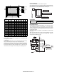
[7] ADJUSTMENTS, SETTING 2. Copier adjustment B. Mechanism section (16) SPF scan position auto adjustment [Function] Used to adjust the SPF scan position automatically. [Operation] 1) With the SPF or the OC cover open, place a chart of black background on the OC glass. (In the SPF standard model, the SPF glass surface is included.) ∗ Use a black chart (UKOG-0011QSZZ) or prepare a chart as shown below. Chart size: 310 x 470, prepared with cutting sheet No. 791 (Black) or an equivalent one.
[8] SIMULATION Code Main Sub 50 1 5 2. Simulation code list Code Main Sub 3 3 8 1 2 3 10 11 12 9 1 5 21 22 1 3 5 10 12 24 25 26 15 1 6 12 14 22 41 43 44 46 57 1 34 2 18 19 20 Function 6 Used to check the operation of the load in the finisher and the control circuit. Used to check and adjust the operation of the developing bias voltage in each copy mode and the control circuit.
(Initial screen) When reading a value from the EEPROM, the value of (EEP value *2) + 200 is used as the set value. Therefore, the set value entered must be an even number. If an odd number is entered the entered odd number + 1 is displayed after pressing [OK] key. (Executing screen) Sim3-3 OUTPUT CHECK 1:JGM1 4:FM-1200 2:JGM2 5:EVM 3:FM-600 6:OFM 1/3 EXEC Sim3-3 OUTPUT CHECK 7:STM 10:JGSL1 8:OGSLR 11:JGSL2 9:OGSLL 12:SHTSL 2/3 EXEC 8 During execution, [EXEC] is highlighted.
The input value is in the increment of –25V.
NO. 1 2 3 4 5 6 7 8 Set value 480 505 530 555 580 605 630 655 Grid High –480V –505V –530V –555V –580V –605V –630V –655V 9 Grid Low –350V –375V –400V –425V –450V –475V –500V –525V 9-1 Purpose Function (Purpose) Section Item *1. The negative value of the set value corresponds to the grid high output voltage. *2. The set values can be selected from the above 8 patterns only. *3. The selected pattern determines the grid high voltage and the grid low voltage.
22 Error code Name Sensor name 22-3 Purpose Adjustment/setting/operation data output/check (display/print) Function Used to check the misfeed positions and the number of (Purpose) misfeed at each position. (When the number of misfeed is considerably great, it can be judged as necessary for repair.) Item Trouble Mis-feed Operation/procedure The misfeed history is displayed in the sequence of recentness by the name of sensors and detectors. Max. 40 items of information can be stored in memory.
The display of the protocol monitor and the soft SW follows this display. Machine serial number Main Control Unit IMC Panel + Panel label code *1 S/N MCU IMC OPE PRINTER NIC FINISHER FAX PRINTER NIC FINISHER FAX When not installed, “- - - - - - - - - -” is displayed. *1: The LCD backlight PWB attachment label code is displayed in three ASCII characters after the version display of 10PE (panel). (Display, XXX section) * Execution is inhibited until GDI or PCL board is securely installed.
Error code PI_TOP PI_END JAM_REV Name Sensor name SPF paper-in SPF P-IN sensor lead edge jam SPF paper-in rear SPF P-IN sensor edge jam SPF duplex SPF P-IN sensor reversion jam PO_TOP SPF paper-out lead edge jam SPF P-IN sensor PO_END SPF paper-out rear edge jam SPF long size error SPF P-OUT sensor SPF P-OUT sensor SPF P-IN sensor SPF P-IN sensor ORG_LONG ORG_SHORT SPF short size error Paper Reached/ Not reached to Sensor Not reached Reached Not reached (paper after reversion) Reached, POUT not
26-14 Function Used to input the Software Key for the PS extension (Purpose) kit. Operation/procedure Display items 0:OFF 1:ON Content AMS is not set automatically. AMS is set automatically. Setting range 0-1 Default 0 The current setup is displayed with ON or OFF. Enter an input (20 digits) of the PS expansion kit soft key and press the [OK] key, and the collating result is displayed with OK or NG.
44 (Auto adjustment) 44-34 1:AE 2:TEXT 3:TEXT/PHOTO 4:PHOTO 5:SUPER PHOTO * 6:AE(TS) 7:TEXT(TS) 8:TEXT/PHOTO(TS) Display items Purpose Function (Purpose) Adjustment Used to adjust the transfer current value. Operation/procedure To support an individual necessity in paper and the environment, it is variable in the range of 5 to 30uA in the increment of 1uA in each mode. When changing +V2, check with +V1 unchanged.
• If the auto exposure mode setup value is changed, the setup value of SIM 46-30 (AE limit setup) is reset to the default value.
Display items 1:TRAY1 Content 1st cassette Setting range 0-99 Remark Default 53 Tray selection: 1st cassette is specified. 2:OPTION Option cassette 1-99 Tray selection: 2nd cassette is specified. 3:MANUAL Manual feed Tray selection: Manual feed cassette is specified. 4:DUPLEX Back print Tray selection: Made by user. Setup of various copy conditions: Similar to the normal copy mode. Use of [SPECIAL FUNCTION] key, [JOB STATUS] key, and [INTERRUPT] key is inhibited.
Operation/procedure Select the mode with the arrow keys, enter the adjustment value with the 10-key, and press the [OK] key. When the [START] key is pressed, a print is made and the display returns to the mode selection menu. (Initial screen) (Input screen) (Executing screen) Sim51-2 RESIST ADJ.
[7-seg LED display] 1: Self print (2-by-4) mode 2: Grid print mode Pressing the [START] key makes a print by 2 by 4 mode. After completion of printing, the menu returns to the initial menu. Pressing the [CA] key cancels the simulation mode. (Input screen) (Executing screen) (Flash Device) (Processing state) PROGRAM RECEIVE BOOTROM ERASE PS KANJI FONT WRITE ESC/P KANJI FONT VERIFY OPTION FONT Press the [CA] key to cancel the simulation and reset.
67-20 Function (Purpose) Used to check the network connection when the scan option is installed. Operation/procedure The network scanner is checked. When [OK] key is pressed, "Please Send Data" and "READY" are displayed, and then ftp is booted from MS-DOS. Put the file name, and data are transmitted from the PC. The process is displayed. Check the display. After completion, the result is displayed. (It takes a little time to display READY.
[10] DISASSEMBLY, ASSEMBLY AND MAINTENANCE 1. Maintenance table N: Check (Check, clean, replace or adjust according to necessity.
All rights reserved. Printed. No part of this publication may be reproduced, stored in a retrieval system, or transmitted, in any form or by any means, electronic; mechanical; photocopying; recording or otherwise without prior written permission of the publisher. Trademark Acknowledgments Microsoft Windows, MS-DOS, Windows NT, Windows 2000 are trademarks of Microsoft Corporation in the U. S. A. and other countries.