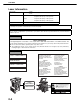
MODEL AR-M355N AR-M455N LASER PRINTER OPERATION MANUAL (for general information and copier operation) Page PART 1: GENERAL INFORMATION • BEFORE USING THE PRODUCT • MANAGING THE MACHINE • PERIPHERAL DEVICES 1-1 2-1 3-1 PART 2: COPIER OPERATION • MAKING COPIES • CONVENIENT COPY FUNCTIONS • MACHINE MAINTENANCE (FOR COPYING) • DOCUMENT FILING FUNCTION • SPECIFICATIONS 4-1 5-1 6-1 7-1 8-1 Be sure to become thoroughly familiar with this manual to gain the maximum benefit from the product.
The power switch positions are marked " I " to indicate power "ON" and " Caution: " to indicate stand-by. For complete electrical disconnection, pull out the main plug. The socket-outlet should be installed near the equipment and should be easily accessible. FOR YOUR RECORDS ... To protect against loss or theft, record and retain for reference the machine's serial number located on the back of the unit.
Part 1: General Information
NOTES ● Considerable care has been taken in preparing this manual. If you have any comments or concerns about the manual, please contact your nearest SHARP Service Department. ● This product has undergone strict quality control and inspection procedures. In the unlikely event that a defect or other problem is discovered, please contact your dealer or nearest SHARP Service Department.
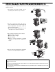
INSTALLATION REQUIREMENTS Improper installation may damage this product. Please note the following during initial installation and whenever the machine is moved. 1.The machine should be installed near an accessible power outlet for easy connection. 2.Be sure to connect the power cord only to a power outlet that meets the specified voltage and current requirements. Also make certain the outlet is properly grounded. ●For the power supply requirements, see the name plate on the back of the main unit. 3.
CAUTIONS 1.Do not touch the photoconductive drum. Scratches or smudges on the drum will cause dirty prints. 2.The fusing unit is extremely hot. Exercise care in this area. 3.Do not look directly at the light source. Doing so may damage your eyes. Fusing unit 4.Five adjusters are provided on all optional stand/paper drawer units. These adjusters should be lowered until they contact the floor. When moving the machine with the optional stand/paper drawer, be sure to raise the adjusters.
CAUTIONS Laser Information Wave length Pulse times Output power 785 nm +10 nm -15 nm North America: 35 cpm model: (4.1 µs ± 4.1 ns)/7 mm 45 cpm model: (5.7 µs ± 5.7 ns)/7 mm Europe: 35 cpm model: (3.8 µs ± 3.8 ns)/7 mm 45 cpm model: (4.4 µs ± 4.4 ns)/7 mm 0.2 mW - 0.4 mW At the production line, the output power of the scanner unit is adjusted to 0.4 MILLIWATT PLUS 8 % and is maintained constant by the operation of the Automatic Power Control (APC).
CONTENTS Page PRODUCT CONFIGURATIONS.................................. 0-1 OPERATION MANUALS.............................................. 0-1 INSTALLATION REQUIREMENTS.............................. 0-2 CAUTIONS................................................................... 0-3 ● Laser Information ................................................. 0-4 CONTENTS ................................................................. 0-5 CHAPTER 1 BEFORE USING THE PRODUCT INTRODUCTION............................
CONTENTS CHAPTER 5 CONVENIENT COPY FUNCTIONS CHAPTER 8 SPECIFICATIONS SPECIAL MODES ........................................................5-2 ● General procedure for using special functions .....5-2 ● Margin shift ...........................................................5-3 ● Erase ....................................................................5-4 ● Dual page copy.....................................................5-5 ● Pamphlet copy......................................................
CHAPTER 1 BEFORE USING THE PRODUCT This chapter contains basic information that should be read before using the product. Page INTRODUCTION .................................................................................... 1-2 MAIN FEATURES ................................................................................... 1-3 PART NAMES AND FUNCTIONS .......................................................... 1-9 ● Exterior...................................................................................
INTRODUCTION Thank you for purchasing a SHARP digital multifunction copier. Please read this manual before using the machine. In particular, be sure to read "INSTALLATION REQUIREMENTS" before using the machine. Please keep this manual close at hand for reference whenever necessary. This manual provides general information on using the machine, such as routine maintenance and how to load paper and remove misfeeds. It also explains how to use the copier and document filing functions.
MAIN FEATURES The digital multifunction copier is capable of performing a variety of functions. This page shows features related to the copy function. ● Job programs See page 1-6 ● Sort mode See page 1-3 ● Mirror Image See page 1-6 ● Group mode See page 1-3 ● B/W Reverse See page 1-6 ● 2-sided Copy See page 1-3 ● Date See page 1-6 (When the duplex module is installed.
MAIN FEATURES Reduction / Enlargement See page 4-15 Copies can be enlarged or reduced to the desired size. Erase See page 5-4 Shadows that appear around the edges of copies of books or thick originals can be erased. Original Original Copy Copy Edge erase Center erase Enlargement Reduction Edge+Center erase XY Zoom See page 4-18 Separate ratio settings can be selected for the length and width of a copy. Original Dual Page Copy Copy Margin Shift See page 5-3 Margins can be added to copies.
MAIN FEATURES Job Build See page 5-8 When you have a very large number of originals, the pages can be scanned in sets. Transparency Insert See page 5-22 Inserts can be automatically inserted between transparencies. Originals (1-sided) Copy 1 Originals (2-sided) 100 sheets 50 sheets Tandem Copy 50 sheets See page 5-9 Two machines can be used to run a large copy job in parallel.
MAIN FEATURES Card Shot See page 5-26 The front and back of a card can be copied onto one sheet of paper. This function is convenient for making copies for certification purposes and helps save paper. Original B/W Reverse White and black can be inverted on a copy to produce a negative image.
MAIN FEATURES Page numbering See page 5-34 Page numbers can be added to copies. Offset mode See page 3-8 Each set of output can be offset slightly from other sets for easy separation. Offset mode 1 Non-Offset mode *When the Finisher or Saddle stitch finisher is installed. Text See page 5-38 Entered text can be added to copies. Staple sort mode See page 3-8, 3-16 Sets of copies can be automatically stapled.
MAIN FEATURES Hole punching See page 3-17 Copies can be punched to add holes. Original Document filing function See CHAPTER 7 A document image can be stored on the hard disk. A stored file can easily be called up and printed or transmitted. Punch positions Printed Document Image HDD Save to machine's hard disk Call up a saved file to reuse Transmitted * When the saddle stitch finisher and punch module are installed.
PART NAMES AND FUNCTIONS Exterior (1) (2) (3) (4) (5) (6) (7) (8) (9) (10) (12) 1 (11) (1) Bypass tray* (7) Operation panel (2) Exit tray* (8) Front cover (13) Open to add toner. (3) Automatic document feeder (See page 4-2.) This automatically feeds and scans multiple sheet originals. Both sides of two-sided originals can be scanned at once. (9) Power switch Press to turn power on and off.
PART NAMES AND FUNCTIONS Interior (14) (15) (16) (18) (14) Duplex module side cover Open when a misfeed has occurred in the duplex module. (15) Side cover latch Push up to open the side cover when a misfeed has occurred in the main unit. (16) Fusing unit Lift up to open the side cover when a misfeed has occurred in the main unit. (17) (19) (17) Toner cartridge (drum/toner cartridge) The toner cartridge must be replaced when indicated on the operation panel.
PART NAMES AND FUNCTIONS Part names and functions of peripheral devices (1) (2) (11) (10) 1 (3) (9) (4) (8) (5) (7) (6) (1) Upper exit tray extension (AR-TE4) Mount this unit to the upper paper exit tray. This extension is needed to support large size paper. (2) Finisher (AR-FN6) Output sheets can either be sorted in page order or grouped by page. Sorted sets or groups are offset stacked for easy separation when removed. Sorted sets can be delivered either stapled or unstapled.
PART NAMES AND FUNCTIONS ■ Other optional equipment ● Barcode font kit (AR-PF1) This kit adds bar code fonts to the machine. ● Facsimile expansion kit (AR-FX12) This kit is required to add fax function. ● Data security kit (AR-FR21, AR-FR21U) This kit is used to erase electronic data from the hard disk and memory immediately after a document is printed or transmitted. ● Additional fax memory (8MB) (AR-MM9) ● Network scanner expansion kit (AR-NS3) This kit is required to add the network scanning feature.
PART NAMES AND FUNCTIONS Operation panel (1) (2) (3) 1 (4) (1) Touch panel The machine status, messages and touch keys are displayed on the panel. The document filing, copy, network scanner*1, and fax*2 functions are used by switching to the screen for the desired function. See the following page. (2) Mode select keys and indicators Use to change modes and the corresponding display on the touch panel. [DOCUMENT FILING] key Press to select the document filing mode. (See page 7-5.
PART NAMES AND FUNCTIONS Touch panel The touch panel screens shown in this manual are printed images, and may appear different from the actual screens. ■ Selecting a function [Example 1] PER. 0 ■ Using the touch panel OK [Example 1] CANCEL Items on the touch panel are easily selectable by 003 / 000 COPY touching the key associ003 / 000 ated with the item with a Suzuki 010 / 000 finger. Selection of an 0666211221 item will be Beep accompanied with a tone beep tone* to confirm the item was selected.
PART NAMES AND FUNCTIONS ■ Job status screen (common to print, copy, fax, network scan and Internet fax) This screen is displayed when the [JOB STATUS] key on the operation panel is pressed. This screen can be used to display the "JOB QUEUE" (showing stored jobs and the current job) or the "COMPLETE" job list (showing finished jobs). This screen can be used to check jobs, interrupt a job in progress to perform another job, and cancel a job.
PART NAMES AND FUNCTIONS (3) [PRINT JOB] key This displays the print job list of print mode (copying, printing, fax reception, Internet fax reception, and self printing). (4) [E-MAIL/FTP] key This displays the transmission status and finished jobs of scan mode (Scan to e-mail, Scan to FTP, and Scan to Desktop) when the network scanner option is installed. (5) [FAX JOB] key This displays the transmission/reception status and finished jobs of fax mode (fax and PC-Fax) when the fax option is installed.
TURNING THE POWER ON AND OFF Use the power switch on the front of the machine to turn the power on or off. "ON" position "OFF" position Power switch CAUTION Before turning off the main power switch, make sure that the communication and data indicators are not blinking on the operation panel. Turning off the main power switch or unplugging the power cord while the lights are blinking may damage the hard disk and cause the data being stored or received to be lost.
AUDITING MODE Auditing mode can be enabled to keep track of the number of pages printed and transmitted (scanned) by each account (up to 500 accounts can be established). The page counts can be viewed and totaled as needed.
CHAPTER 2 MANAGING THE MACHINE This chapter explains how to load paper, replace the toner cartridge, and remove paper misfeeds. It also contains information about supplies. Page LOADING PAPER................................................................................... 2-2 ● Loading paper in paper tray 1 ......................................................... 2-2 ● Changing the paper size in paper tray 1 ......................................... 2-2 ● Specifications of paper trays ..................
LOADING PAPER If the paper runs out during printing, a message will appear in the display. Follow the procedure below to load paper. NOTES ● Do not use curled or folded paper. Doing so may cause a misfeed. ● For best results use paper supplied by SHARP. (See page 2-4.) ● When you change the paper type and size in paper tray 1, set the paper type and size referring to "Setting the paper type and paper size" (page 2-5). ● Do not place heavy objects or press hard on any tray which is pulled out.
LOADING PAPER Specifications of paper trays The specifications for types and sizes of paper that can be used in each tray are shown below. Tray Tray No. (tray name) Applicable paper types Applicable paper sizes Paper weight Paper tray 1 Tray 1 Plain paper (Refer to the next page ● 8-1/2" x 11", A4, B5 for applicable plain papers.) Multi purpose drawer /bypass tray Tray 2 /bypass tray Plain paper (Refer to the next page ● If "AUTO-INCH" is selected in setting the 16 to 34 lbs.
LOADING PAPER ■ Applicable plain paper For satisfactory results, plain paper must conform to the following requirements. Paper in AB system Paper in inch system A5 to A3 Plain paper 5-1/2" x 8-1/2" to 11"x17" 16 to 28 lbs. or 60 to 105 g/m2 Recycled, colored, pre-punched, pre-printed and letterhead papers must conform to the same conditions as above. ■ Applicable special paper For satisfactory results, special paper must conform to the following requirements.
LOADING PAPER Setting the paper type and paper size Follow these steps to change the paper type setting if the paper type is changed in either paper tray. For the paper types that can be used in each tray, see page 2-3. 1 Press the [CUSTOM SETTINGS] key. The custom setting menu screen will appear. 5 Touch the [TYPE / SIZE] key. PER TRAY SETTINGS TYPE / SIZE TRAY 2 PRINT 2 Touch the [PAPER TRAY SETTINGS] key. The paper tray selection screen will appear.
LOADING PAPER the size of paper that was loaded in 7 Select the tray. the [OK] key in the size setting 8 Touch screen. Touch the appropriate keys (checkboxes). You will return to the tray setting screen of step 4. CUSTOM SETTINGS TYPE TRAY 2 TYPE/SIZE SETTING SIZE TYPE AUTO-INCH PLAIN AUTO-AB SIZE INPUT output functions that can be used 9 Select with the selected tray.
LOADING PAPER Programming and editing paper types To program or edit the name of a paper type or set paper attributes, follow the steps below. steps 1 and 2 of "Setting the paper 1 Follow type and paper size" (page 2-5) the [PAPER TYPE REGISTRATION] 2 Touch key. "FIXED PAPER SIDE" : Select when paper is to be loaded print side down in the tray. Make sure a checkmark does not appear when paper is to be loaded print side up.
LOADING PAPER Loading paper in the multi purpose drawer The method of loading paper into the multipurpose drawer is the same as for paper tray 1 described on page 2-2. For specifications of paper, see page 2-3. When loading envelopes, postcards or transparency film, follow the descriptions below. ● Two maximum height lines are indicated: one for plain paper and one for special paper. Maximum height line for plain paper Do not exceed this line when loading plain paper.
LOADING PAPER Printing onto envelopes ● Do not use envelopes that have metal clasps, plastic snaps, string closures, windows, linings, self-adhesive patches or synthetic materials. Attempting to print on these may cause misfeeds, inadequate toner adherence or other trouble. ● Creases or smudging may occur. This is especially true of embossed surfaces and other irregular surfaces.
LOADING PAPER ■ Loading transparency film Be sure to load the transparency film with the white label side up. Make sure no image will be printed on the label. Printing on the label may cause smudges on prints. Transparency film must be set in the portrait orientation. Specifications (multi purpose drawer) Name Multi purpose drawer Paper size/weight See specifications of paper trays on page 2-3. Paper capacity 500 sheets (20 lbs.
LOADING PAPER Loading paper in the stand/MPD & 2000 sheet paper drawer Upper paper tray: The upper paper tray is equivalent to the multi purpose drawer. The method of loading paper and the paper that can be used are the same as for the multi purpose drawer. Refer to the description of the multi purpose drawer (see page 2-8). Lower paper tray: The lower paper tray is a large capacity tray that holds 2,000 sheets of 8-1/2" x 11" or A4 paper (20 lbs. (80 g/m2)).
CUSTOM SETTINGS The items that can be set with the custom settings are shown below. ● Total count . . . . . . . . . . . . . . . . . . The number of pages processed by the machine and optional equipment can be displayed. (See page 2-14) ● Default settings . . . . . . . . . . . . . . Used to configure the screen contrast, date and time, and keyboard selection*1 settings. (See page 2-14) ● List print . . . . . . . . . . . . . . . . . . . . Used to print lists of settings and fonts.
CUSTOM SETTINGS 5 Touch the [DATE FORMAT] key. The following screen appears. CUSTOM SETTINGS OK DATE FORMAT 2004/10/20/MON 14:27 MM/DD/YYYY DAY-NAME POSITION FIRST 12-HOUR DD/MM/YYYY LAST 24-HOUR YYYY/MM/DD More information on setting procedures In the following type of screen, a setting is selected by touching the key so that a checkmark ( ) appears. The settings below are configured to allow use of tray 1 in print, copy, and fax modes. To display the next screen, touch the or keys.
CUSTOM SETTINGS About the settings ■ Total count ■ List print This displays the following sheet counts (the counts that can be displayed vary depending on the options installed): This is used to print lists of machine settings and a test page to check resident fonts. The following lists and pages are available: (1) Number of pages output by the machine. (2) Number of original pages transmitted by the machine.
REPLACING THE TONER CARTRIDGE When toner runs low, a message will appear to inform you that the toner cartridge must be replaced. NOTE To view the approximate amount of toner remaining, hold down the [COPY] key during printing or when the machine is on standby. The percentage of toner remaining will appear in the display while you hold down the key. When the percentage falls to "25-0%" , obtain a new toner cartridge and keep it ready for replacement. Follow the steps below to replace the toner cartridge.
STORAGE OF SUPPLIES Standard supplies for this product that can replaced by the user include paper, toner cartridges, and staple cartridges for the finisher. For best copying results, be sure to use only Sharp Genuine Supplies which are designed, engineered, and tested to maximize the life and performance of Sharp products. Look for the Genuine Supplies label on the toner package. GENUINE SUPPLIES ■ Proper storage 1.
MISFEED REMOVAL When a misfeed has occurred during printing, the message "A MISFEED HAS OCCURRED". will appear in the touch panel display of the operation panel and printing including copying and facsimile output will stop. The approximate misfeed locations are indicated with " " shown in the illustration below. The page numbers for detailed information on misfeed removal are also shown.
MISFEED REMOVAL Misfeed in the transport area, fusing area, and exit area o CAUTION The fusing unit is hot. Take care in removing paper. (Do not touch the metal parts.) the duplex module and slide it to 1 Unlatch the left. Unlatch the module and gently move the module away from the machine. If the machine is not equipped with a duplex module, open the side cover similarly. Roller rotating knob B CAUTION The fusing unit is hot. Take care in removing paper. (Do not touch any metal parts.
MISFEED REMOVAL Misfeed in the duplex module the duplex module and slide it to 1 Unlatch the left. Unlatch the unit and gently move the module away from the machine. the duplex module has an exit tray, 2 Ifrotate it up out of the way and open the cover of the duplex module. If no exit tray is attached, just open the cover of the duplex module and ignore any reference to the tray in the following steps. 5 Gently close the duplex module.
MISFEED REMOVAL Misfeed in the paper feed area NOTE Be sure to follow the misfeed removal sequence. Do not pull the tray out immediately as the misfeed may have occurred with paper partially fed out of the tray. Open the left cover and see if there is misfed paper first (steps 1 and 2). If you open the tray without checking, the partially fed paper may tear and leave torn pieces in the machine, increasing the difficulty of removal.
MISFEED REMOVAL ■ Misfeed in the multi purpose drawer Unlatch the duplex module and slide it to the left. 1 Unlatch the module and gently move the module away from the machine. If the machine is not equipped with a duplex module, open the side cover similarly. the 2 Open drawer. left cover of the stand/paper Hold the knob and gently open the cover. If the machine is not equipped with a stand/ paper drawer, open the left cover of the multi purpose drawer. 3 Remove the misfed paper.
REMOVING AN ORIGINAL MISFEED Removing a misfed original from the automatic document feeder If an original misfeed occurs in the automatic document feeder, follow the steps below to remove the misfed original. NOTES ● For misfeed removal in the main unit and other peripheral devices, see page 2-17 ● When a misfeed occurs, touch the [INFORMATION] key to display detailed information for misfeed removal. Check locations A and B in the diagram at left to remove the original.
TROUBLESHOOTING Check the following troubleshooting list before requesting service as many problems can be fixed by the user. If you are unable to solve the problem by checking the list, turn off the power switch, unplug the power cord. Problems related to general use of the machine are described below. For problems related to the copy function, see page 6-3. For problems related to document filing, see page 7-28. For fax, printer, and network scanner problems, see the manuals for those functions.
TROUBLESHOOTING Problem Printing stops before the job is finished Check Solution or cause If too many pages collect on the output tray, the tray full sensor activates and Remove the paper from the output tray. stops printing. You have run out of paper. Load paper. (Page 2-2) Smudges on printed Does a message appear indicating the sheets need for maintenance? Please contact the your dealer as soon as possible.
TROUBLESHOOTING Problem Check Solution or cause Is paper other than SHARPUse SHARP-recommended paper. (Page 2-16) recommended paper being used? Is paper size or weight out of the allowable range? Use paper in the allowable range. Paper damp? Be sure to store paper in the wrapper in a dry location and do not store paper in a location that is ●humid ●at a high temperature or an extremely low temperature ●exposed to direct sunlight ●dusty.
CHAPTER 3 PERIPHERAL DEVICES This chapter describes operating instructions for the Mail-Bin Stacker, the Finisher, the Saddle Stitch Finisher, and the Duplex Module. Page DUPLEX MODULE ................................................................................. 3-2 ● Part names...................................................................................... 3-2 ● Specifications ..................................................................................
DUPLEX MODULE If a duplex module is installed, printing onto both sides of paper can be performed. Two types of duplex modules are available: duplex module/bypass tray and duplex module. The descriptions in this manual are for the duplex module/bypass tray. For information on misfeed removal for these modules, see page 2-19. Part names Exit tray The tray is extendable to support large size paper. Extend the tray when 11" x 17", 8-1/2" x 14", 8-1/2" x 13", A3 or B4 paper is being used.
DUPLEX MODULE Loading paper in the bypass tray The bypass tray can be used for plain paper and special paper including labels. Up to 100 sheets of standard paper can be set. For paper types that can be used in the bypass tray, refer to page 2-3. NOTE If the paper type or size is changed, be sure to enter the paper type and size as in step 4. 1 Open the bypass tray. Bypass tray extension When setting 11"x 17", 8-1/2" x 14", 8-1/2" x 13, A3 or B4 paper, be sure to extend the bypass tray extension.
DUPLEX MODULE Troubleshooting (concerning the duplex module) Check the list below before calling for service. Problem Check Solution or cause Message indicating the paper type Special paper cannot be used for two-sided cannot be used for two-sided printing printing. Use a paper type adequate for displayed? two-sided printing. (See pages 2-4 and 3-2.) The machine will not print duplex prints. Printed images onto paper from the bypass tray are skewed. A paper misfeed occurs in the bypass tray.
MAIL-BIN STACKER The mail-bin stacker has 7 mail bins which can each be designated to receive printed output from a user or a group of users . Output paper in the copy mode and the fax mode will be delivered to the top tray of the stacker separated from printed output. (Printed output can also be delivered to the top tray.) Part names Top cover Open for misfeed removal. Front cover Open for misfeed removal. Top tray Output paper from the printer, copier, and facsimile features can be delivered here.
MAIL-BIN STACKER Misfeed in the mail-bin stacker If a misfeed has occurred in the mail-bin stacker during printing, remove the misfed paper following the procedure below. 1 Open the top cover. Top cover 6 Remove the misfed paper. Move the tab in the direction of the arrow as shown in the illustration to open the top cover. 2 Remove the misfed paper. Be careful not to tear the misfed paper during removal. After removing the paper, press down on the top cover to close it.
FINISHER The finisher can deliver collated sets either stapled or unstapled. Unstapled sets can be offset stacked from the previous set for easy separation of the sets. Part names Latch Top tray Printer, copier and fax output can be delivered here. To print onto large paper (11" x 17", 8-1/2" x 14", 8-1/2" x 13", A3 or B4), extend the tray. Release the latch to open the finisher for misfeed removal. Top cover Open for removal.
FINISHER Finisher functions ■ Group mode ■ Sort mode Sorted sets will be delivered. Original Groups of prints or copies of the same page will be delivered. Printouts Printouts Original ■ Offset mode Offset mode Non-offset mode Sets will move from side to side so that each set or group will be offset from the previous set or group for easy separation. The offset function can only be used in the offset tray. Stapled sets will not be offset.
FINISHER Using the finisher functions When the [OUTPUT] key on the main screen of copy mode is touched, a screen for selecting the sort/group/staple sort functions and selecting an exit tray will appear. As a selection is made, the touch key for the selection will be highlighted. OUTPUT OK SORT (8) TOP TRAY (7) STAPLE SORT OFFSET TRAY (6) GROUP OFFSET (1) (2) (3) (1) [GROUP] key (See page 3-8.) When Group is selected, all copies of the same original will be grouped.
FINISHER Staple cartridge replacement When the staple cartridge becomes empty, the message "Add staples." will appear in the message display of the operation panel. Follow the procedure below to replace the staple cartridge. 1 Open the front cover. NOTES ● Do not remove the tape from the cartridge before inserting the staple cartridge into the box. ● When reinstalling the staple box, push it in until it clicks into place. the tape from the staple cartridge 6 Remove by pulling it straight.
FINISHER ■ Checking the staple unit If the message "CHECK THE STAPLER UNIT" or "CHECK STAPLER POSITION OR STAPLER JAM" appears, follow the procedure below. 1 Open the finisher compiler. Release the latch to open the finisher compiler. the misfed paper from the stapler 2 Remove compiler. Be careful not to tear the misfed paper during removal. 3 Close the finisher compiler. 7 Raise the lever at the end of the staple box. Remove the top staple if it is bent.
FINISHER Misfeed in the finisher When a misfeed occurs in the finisher, remove the misfed paper following the procedure below. the misfed paper from the output 1 Remove area. the paper 5 Raise misfed paper. Be careful not to tear the misfed paper during removal. guide and remove the Be careful not to tear the misfed paper during removal. Paper guide 2 Open the finisher top cover. Top cover Move the tab in the direction of the arrow as shown in the illustration to open the top cover.
FINISHER Troubleshooting finisher problems Check the list below before calling for service. Problem Check Solution or cause Are any finisher covers open? The finisher does not operate. Stapling cannot be performed. Message indicating need to remove paper from the stapler compiler displayed? Close all covers. Open the finisher as described in step 4 on page 3-12 and remove all paper from the stapler compiler.
SADDLE STITCH FINISHER The saddle stitch finisher can automatically place two staples for centerline binding of prints or copies and fold them along the centerline. An optional hole punching unit is available for installation into the finisher. Part names Stapler compiler Paper to be stapled is stacked temporarily. Top cover Open for misfeed removal. Stapler section Open the front cover and pull out this section to replace the staple cartridge or to remove jammed staples.
SADDLE STITCH FINISHER Stapling capacity 8-1/2" x 11" or A4 or smaller size: 50 sheets*(20 lbs. or 80 g/m2) 8-1/2" x 14" or B4 or larger size: 25 sheets*(20 lbs. or 80 g/m2) *Up to two sheets of 34 lbs. or 128 g/m2 paper can be included as covers. Staples Upper tray: Single staple can be placed in the top left or lower left corners or two staples can be centered on the left side.
SADDLE STITCH FINISHER ■ Staple sort mode Collated sets of prints or copies will be stapled and delivered to the offset tray. When saddle stitching is selected, the prints or copies will be stapled at the center and delivered to the saddle stitch tray. The stapling positions, orientation, paper size for stapling, and stapling capacity are shown below.
SADDLE STITCH FINISHER ■ Saddle stitch function The saddle stitch finisher can automatically place two staples for centerline binding of prints or copies and fold them along the centerline. 6 4 2 ■ Hole punching (only if a punch module is installed) If the saddle stitch finisher is equipped with a hole punch module, printed paper can be hole punched and delivered to the offset tray. Saddle stitching and hole punching cannot be selected at the same time.
SADDLE STITCH FINISHER Using the saddle stitch finisher When [OUTPUT] is selected on the main screen of copy mode, a screen for making selections for sort, group, staple sort, saddle stitch, punch and exit tray will appear. (1)(2)(3) (4)(5) (6) (7) OUTPUT OK OFFSET TRAY SORT CENTER TRAY STAPLE SORT GROUP SADDLE STITCH PUNCH (9) (10) OFFSET (8) (1) [GROUP] key (See page 3-15.) When Group is selected, all copies of the same original will be grouped. (2) [STAPLE SORT] key (See page 3-16.
SADDLE STITCH FINISHER Staple cartridge replacement and staple jam removal When the staple cartridge becomes empty or staples become jammed, a message will appear in the message display of the operation panel. Follow the procedure below to replace the staple cartridge or remove jammed staples. ■ Staple cartridge replacement 1 Open the front cover. a new 6 Insert staple box. staple cartridge into the After inserting the staple cartridge, press down on the staple box cover to lock the cartridge in place.
SADDLE STITCH FINISHER ■ Staple jam removal the saddle stitch finisher and slide 1 Unlatch it away from the machine. saddle stitch was selected, open the 5 Ifsaddle stitch section cover. 2 Open the front cover. 6 Remove the misfed paper. Be careful not to tear the misfed paper during removal. roller rotating knob C as shown in the 3 Turn illustration until the blue indication is 7 Close the saddle stitch section cover. seen. Roller rotating knob C Blue the 4 Remove compiler.
SADDLE STITCH FINISHER roller rotating knob A in the direction 9 Turn of the arrow to move the staple unit to the 12 Return the lever to its original position. front. Turn the roller rotating knob until the triangle mark is aligned with the index. Roller rotating knob A Staple unit 13 Reinstall the staple box. 10 Remove the staple box. Push the staple box in until it clicks into place. 11 Raise the lever at the end of the staple box. Remove the top staple if it is bent.
SADDLE STITCH FINISHER Misfeed in the saddle stitch finisher When a misfeed occurs in the saddle stitch finisher, remove the misfed paper following the procedure below. the detach button and separate the 1 Press saddle stitch finisher from the machine. 5 Remove the misfed paper. Remove the paper gently, taking care not to tear it. CAUTION The saddle stitch finisher and the machine are connected at the rear. Exercise caution when pulling them apart. any 2 Remove machine. 6 Close the top cover.
SADDLE STITCH FINISHER 10 Open the front cover. the saddle stitch finisher back onto the 15 Push machine. roller rotating knob D in the direction of 11 Rotate the arrow. Roller rotating knob D any misfed paper from the saddle 12 Remove stitch tray. 3 Remove the paper gently, taking care not to tear it. 13 Close the cover of the saddle stitch section. 14 Close the front cover.
SADDLE STITCH FINISHER Troubleshooting (concerning the saddle stitch finisher) Check the list below before calling for service. Problem Check The saddle stitch finisher does not operate. Are any saddle stitch finisher covers open? Close all covers. (See page 3-14.) Message indicating need to remove paper from the stapler compiler displayed? Remove all remaining paper from the stapler compiler referring to step 4 on page 3-20.
Part 2: Copier Operation
CHAPTER 4 MAKING COPIES This chapter explains the basic procedures for making copies, including selection of the copy ratio and other copy settings. Page AUTOMATIC DOCUMENT FEEDER...................................................... 4-2 ● Acceptable originals ........................................................................ 4-2 PLACING ORIGINALS............................................................................ 4-3 CHECKING THE SIZE OF A PLACED ORIGINAL .................................
AUTOMATIC DOCUMENT FEEDER The automatic document feeder automatically feeds originals into the machine, making continuous copying possible. In addition, both sides of two-sided sheet originals can be simultaneously scanned. This function is convenient when you have a large number of original pages to scan.
PLACING ORIGINALS ■ Using the feeder automatic document ■ Using the document glass the document cover, make sure that 1 Open an original has not been left on the Open the document cover, place the original face down on the document glass, and then gently close the document cover. document glass, and then gently close the document cover. Original size detector To make a copy of a small original such as a postcard, use the [PAPER SELECT] key to select the desired paper size.
PLACING ORIGINALS ■ Standard original placement orientations [Example 1] Document feeder tray Top Bottom Document glass Top Bottom [Example 2] Top Top Bottom Place originals in the document feeder tray or on the document glass so that the top and bottom of the original is positioned as shown in the illustration. If not, staples will be incorrectly positioned and some special features may not give the expected result.
CHECKING THE SIZE OF A PLACED ORIGINAL If the placed original is a standard size, the size will be automatically detected (automatic original detection function) and displayed in the touch panel. Make sure that the correct size has been detected. (A) :The original size is displayed. (B) :[AUTO] appears when the automatic original detection function is operating.
STORING, DELETING, AND USING ORIGINAL SIZES Up to 9 special original sizes can be stored. Stored sizes can be easily called up and are not erased if the power is turned off. Storing a frequently used original size saves you the trouble of manually setting the size each time you copy that size of document. ● To cancel an original size storing, using, or deleting operation, press the [CA] key or touch the [ORIGINAL] key on the screen. Storing or deleting an original size 1 Touch the [ORIGINAL] key.
NORMAL COPYING This section describes the normal copying procedure. Making copies with the automatic document feeder ■ 1-sided copies of 1-sided originals Original Copy the originals in the document feeder 1 Place tray. (pages 4-3 to 4-6) 5 Touch the [OK] key. 0 OK 4 sure that the 1-sided to 1-sided copy 2 Make mode is selected. The one-sided to oneORIGINAL sided mode is selected when no icon for a twosided mode appears in 81/2x11 8 x11 the dashed area on the 8 x11 11x17 display.
NORMAL COPYING 7 Select the desired output mode (page 4-9). The sort mode is the default mode. To select the group OUTPUT mode, touch the [OUTPUT] key, then touch the [GROUP] key FILE on the output setting screen, and then touch the [OK] key on the setting screen. 2-SIDED COPY the numeric keys to set the desired 8 Use number of copies. Up to 999 can be set. If you are only making a single copy, the copy can be made with the copy number display showing "0".
NORMAL COPYING ■ Copy output (sort and group) Example: Making five sets or five copies each of three originals ● Sorting copies into sets Original Five sets of copies OUTPUT SORT SPECIAL MODES 2-SIDED COPY OUTPUT GROUP Set the number of copies (5) Touch the [OUTPUT] key Touch the [SORT] key Press the [START] key When using the automatic document feeder, sorting is automatically selected when the original is placed in the document feeder.
NORMAL COPYING Automatic two-sided document feeder copying using the automatic When the optional duplex module is installed, the following automatic two-sided copying can be performed. The paper is automatically turned over during copying, allowing two-sided copies to be made with ease. Original Copy 1. Automatic two-sided copying from one-sided originals 2. Automatic two-sided copying from two-sided originals 3.
NORMAL COPYING Copying from the document glass When copying originals which cannot be fed from the automatic document feeder such as thick originals, open the document cover and copy the originals from the document glass. ■ 1-sided copies of 1-sided originals Original Copy the original on the document glass. 1 Place (pages 4-3 to 4-6) that paper of the same size as the 3 Ensure original is automatically selected*.
NORMAL COPYING the desired output mode. (page 44 Select 9.) 2-SIDED COPY OUTPUT FILE Group mode default mode. is 7 Press the [START] key. Replace the original with the next original and press the [START] key. Repeat this operation until all originals have been scanned. the To select sort mode, touch the [OUTPUT] key, touch the [SORT] key in the screen that appears, and then touch the [OK] key. the numeric keys to set the desired 5 Use number of copies. Up to 999 can be set.
NORMAL COPYING Automatic two-sided copying from the document glass When the optional duplex module is installed, the following automatic two-sided copying can be performed. The paper is automatically turned over during copying, allowing two-sided copies to be made with ease. Original Copy the original on the document glass. 1 Place (pages 4-3 to 4-6) Original scale mark 5½ x 8½ or A5 8½x11 or A4 Original scale mark 8½x14 or B4 11x17 or A3 2 Touch the [2-SIDED COPY] key.
ADJUSTING THE EXPOSURE Select an appropriate exposure mode for the original to be copied. The selections are AUTO, TEXT, TEXT/PHOTO and PHOTO. ■ Automatic exposure adjustment UTO The default exposure ORIGINAL setting is "AUTO", which automatically adjusts the exposure for the original. To select the exposure mode, or to 1 AUTO 8 /2 x11 manually adjust the PAPER SELE T exposure level, follow the steps below.
REDUCTION/ENLARGEMENT/ZOOM Reduction and enlargement ratios can be selected automatically or manually. ● Automatic selection: Auto image (see below) ● Manual selection: Preset copy ratios/zoom (see page 4-16) Automatic selection (auto image) The reduction or enlargement ratio will be selected automatically based on the original size and the selected paper size. the original in the document feeder 1 Place tray or on the document glass. (pages 4-3 to 4-6) The detected original size will be displayed.
REDUCTION/ENLARGEMENT/ZOOM Manual selection (preset copy ratios/zoom) Preset ratios (maximum 400%, minimum 25%) can be selected with the enlargement and reduction keys. In addition, the zoom keys can be used to select any ratio from 25% to 400% in increments of 1%. the original in the document feeder 1 Place tray or on the document glass.
REDUCTION/ENLARGEMENT/ZOOM sure that an appropriate paper size 6 Make has been selected based on the selected ratio. ORIGIN L AUTO EXPOSURE AUTO 81/2x11 PAPER SELECT needed, touch the 8 If[QUICK FILE] key. [FILE] key or the Either key can be touched to store the scanned document image on the machine's QUICK FILE hard disk. The stored image can be re-used later. For more information on this function, see "Document filing function" in chapter 7.
REDUCTION/ENLARGEMENT/ZOOM XY ZOOM The XY ZOOM feature allows the horizontal and vertical copy ratios to be changed separately. The ratios can set from 25% to 400% in increments of 1%. Example: Selecting 100% for the length and 50% for the width Copy Original the original in the document feeder 1 Place tray or on the document glass. (pages 4-3 to 4-6) NOTE When the original is placed in the document feeder, the ratio can be set from 25% to 200%. 2 Touch the [COPY RATIO] key.
REDUCTION/ENLARGEMENT/ZOOM the 7 Use ZOOM ([ reduction, enlargement, and ], [ ]) keys to change the copy ratio in the vertical (Y) direction. 77% X 50 70 Y 64% any desired copy settings such as 10 Select the exposure or number of copies, and then press the [START] key. A fixed ratio key will not become highlighted when touched. ZOOM 50% 50 77 Y The zoom keys can be used to change the ratio from 25% to 400% in increments of 1%.
SPECIAL PAPERS The tray 2 and the bypass tray on the optional duplex module with bypass tray can be used to make copies on transparencies, postcards, label sheets, envelopes*1, and plain paper. *1 Envelopes can be placed in the tray 2. the original in the document feeder 1 Place tray or on the document glass. (pages 4-3 5 Select the bypass tray. RE DY TO SC N FOR COPY to 4-6) 8 x11 P 1/ 2 11x17 P PLAIN 11x17 P 8 x11 P 1/ 2 8 x11 1/ 2 2 Load the special paper in the bypass tray.
CHAPTER 5 CONVENIENT COPY FUNCTIONS This chapter explains special-purpose functions, storing of copy settings, and other convenient functions. Please select and read sections of this chapter as needed. Page SPECIAL MODES................................................................................... 5-2 ● General procedure for using special functions................................ 5-2 ● Margin shift...................................................................................... 5-3 ● Erase.......
SPECIAL MODES Touch the [SPECIAL MODES] key in the main screen of copy mode to open the special modes screen. The following functions can be selected in the special modes screen. Touch the [SPECIAL MODES] key in the main screen. (2) (1) (3) READY TO SCAN FOR COPY.
SPECIAL MODES Margin shift The margin shift function will automatically shift the text or image on the copy paper approximately 1/2" (10 mm) in its initial setting. This function is convenient when stapling or binding copies with a string. NOTES ● The initial setting for the margin width can be changed in the key operator programs to any value from 0 to 1" (0 to 20 mm).
SPECIAL MODES Erase The erase function is used to erase the shadow lines on copies produced when copying thick originals or books. The erase modes that can be selected are shown below. The erase width is approximately 1/2" (10 mm) in it's initial setting. NOTE The initial setting for the erasure width can be changed in the key operator programs to any value from 0 to 1" (0 to 20 mm).
SPECIAL MODES Dual page copy The dual page copy function produces separate copies of two documents placed side by side on the document glass. This function is especially useful when copying books and other bound documents. [Example] Copying right and left pages of a book Book original Dual page copy ●The dual page copy function can be used only when copying from the document glass. The automatic document feeder cannot be used with this function. ●Only 8-1/2" x 11" (A4) paper can be used.
SPECIAL MODES Pamphlet copy The pamphlet copy function is used to arrange copies in proper order for eventual center-stapling and folding into a booklet. Two original pages are copied onto each side of copy paper. Four pages are, therefore, copied onto one sheet. This function is convenient for arranging copies into an attractive booklet or pamphlet. NOTE To make pamphlet copies of a book or other bound original, use the book copy function (page 5-25).
SPECIAL MODES whether or not you wish to copy on 5 Select the cover ("YES" or "NO"). the original in the document feeder 9 Place or on the document glass. (page 4-3) PRINT ON COVER YES that the desired paper size has 10 Ensure been automatically selected based on the NO original size. UTO EXPOSURE 6 Select the paper tray for the cover. CANCEL OK PAPER TRAY (1) TRAY2 (2) 81/2x11 PLAIN (1)The currently selected paper tray for the cover is displayed.
SPECIAL MODES Job build Use job build mode when you need to copy more originals than can be placed in the document feeder at once. The maximum number of originals that can be placed in the document feeder at once is 50 sheets (30 sheets when the size is B4 or larger; for more information see "Acceptable originals" on page 4-2). This function lets you divide and scan the originals in sets. This function allows the original pages to be scanned in sets.
SPECIAL MODES Tandem copy Two machines connected to the same network can be used to run a large copy job in parallel. By dividing the job in half, approximately half the time is required to complete the job. To use this function, two machines must be connected to your network as network printers. Even if more machines are connected to the network, this function can only be used to have one other machine share a job.
SPECIAL MODES 5 Press the [START] key. NOTES ● To perform tandem copying, the server machine and client machine must meet certain conditions. After the [START] key is pressed on the server machine, the server machine verifies that the conditions have been met. If the conditions have not been met, tandem copying does not begin and "TANDEM OUTPUT IS NOT ALLOWED. OUTPUT ALL SETS USING MASTER MACHINE?" appears in the display. To have the server machine make all the copies, touch the [OK] key.
SPECIAL MODES Covers/inserts A different type of paper can be inserted in positions corresponding to front and back covers of a copy job when the automatic document feeder is used. A different type of paper can also be automatically added as an insert at specified pages. ● Covers/inserts can be disabled in the key operator programs (page 11 of the key operator's guide).
SPECIAL MODES ■ Procedure for inserting front and back cover paper The paper for the front cover is called the front cover paper ("FRONT COVER" in the touch panel). The paper for the back cover is called the back cover paper ("BACK COVER" in the touch panel). ●Examples of insertion methods for the front and back cover paper are given on pages 5-17 to 5-20. To display the special modes screen... See "General procedure for using special functions" on page 5-2.
SPECIAL MODES ■ Procedure for adding inserts You can have different paper automatically inserted as an insert at a specified pages. Two types of insert paper can be used. These are specified with the [INSERTION TYPE A SETTING] key and [INSERTION TYPE B SETTING] in the touch panel. ●Examples of insertion methods for insert paper are given on page 5-21. To display the special modes screen... See "General procedure for using special functions" on page 5-2.
SPECIAL MODES the [INSERTION SETTINGS] key to 8 Touch specify the pages where you wish to insert wish to insert a different paper with 11 Iftheyou[INSERTION TYPE B SETTING] key, the insert papers of [INSERTION TYPE A SETTING] and [INSERTION TYPE B SETTING]. repeat steps 2 through 6. Use the [INSERTION TYPE B SETTING] key instead of the [INSERTION TYPE A SETTING] key, and the [INSERTION TYPE B] key instead of the [INSERTION TYPE A] key.
SPECIAL MODES ■ Checking, editing, and deleting cover/insert pages The [PAGE LAYOUT] key appears after covers/inserts settings are configured (the settings of step 1 through step 7 on pages 5-12 and 5-13). The [PAGE LAYOUT] key is used for the following: ● To display the status of covers/inserts pages ● To edit, delete, or add inserted pages (3)To edit or delete the insertion page of an insert, To display the [PAGE LAYOUT] key...
SPECIAL MODES ■ Examples of covers and inserts The relations between the originals and finished copies when covers or inserts are inserted are shown on the following pages.
SPECIAL MODES ■ Covers (One-sided copying of one-sided originals) One-sided copies are made of the following one-sided originals.
SPECIAL MODES ■ Covers (Two-sided copying of one-sided originals) Two-sided copies are made of the following one-sided originals.
SPECIAL MODES ■ Covers (One-sided copying of Two-sided originals) One-sided copies are made of the following two-sided originals.
SPECIAL MODES ■ Covers (Two-sided copying of two-sided originals) Two-sided copies are made of the following two-sided originals.
SPECIAL MODES ■ Inserts (One-sided copying of one-sided originals) One-sided and two-sided copying is performed using the following one-sided originals. The insertion page of the insert is set to page 3.
SPECIAL MODES Transparency film with insert sheets When copying onto transparency film, blank insert sheets can be placed between transparent sheets. Example: Inserting insert sheets between transparencies ● This function only operates in "one-sided to onesided" and "two-sided to one-sided" modes. ● Multiple copies cannot be selected in this mode. ● The inserts are inserted under each transparency as shown at left. ● Select insert paper that is the same size as the transparencies.
SPECIAL MODES 9 Select the tray 2. the insertion conditions for the insert 11 Set paper. OR COPY. OK AUTO ORIGIN 1. 81/2 x11 PLAIN 2. 81/2x11 TRANSPARENCY 3. 11x17 PLAIN PAPE 4. 81/2x11 PLAIN 100 COPY R CANCEL AUT EXPOS PRINT ON INSERT SHEETS YES NO To display the special modes screen... See "General procedure for using special functions" on page 5-2. the [TRANSPARENCY INSERTS] 10Touch key in the special modes screen (2nd screen).
SPECIAL MODES To display the special modes screen... See "General procedure for using special functions" on page 5-2. the [MULTI SHOT] key in the special 1 Touch modes screen (2nd screen). TRANSPARENCY INSERTS MULTI SHOT CARD SHOT MIRROR IMAGE The MULTI SHOT setting screen will appear. A multi shot icon ( , etc.) will also appear in the upper left of the screen to indicate that the function is turned on. the number of images to be copied 2 Select onto one sheet of copy paper.
SPECIAL MODES Book copy This function is convenient when you wish to compile copies of books or other bound originals into an attractive pamphlet format. The two pages of the open book are scanned as a set, and two pages each are copied onto the front and back sides of the copy paper (four pages are copied onto one sheet of copy paper). This allows the copies to be folded down the center and made into a pamphlet.
SPECIAL MODES Card shot When copying a card, this function allows you to combine the front and back sides on a single sheet of paper. This function is convenient for making copies for certification purposes and helps save paper. Original ● Copying is only possible on standard size paper. ● A copy ratio cannot be selected when using this function. ● The image cannot be rotated when using this function.
SPECIAL MODES 4 Touch the outer [OK] key. OK CANCEL OK You will return to the main screen of copy mode. the back side of the original face 8 Place down on the document glass (see step 5). 9 Press the [START] key. SIZE RESET The back side of the card is scanned. FIT TO PAGE 5 Place the original on the document glass. Place the front side of the original face down and close the document cover. 10Touch the [READ-END] key.
SPECIAL MODES Mirror image This function is used to print a mirror image of the original. The images will be inverted in the right to left direction on the copies. Original Copy the [OK] key on the special modes 2 Touch screen. To display the special modes screen... See "General procedure for using special functions" on page 5-2. You will return to the main screen of copy mode. the [MIRROR IMAGE] key in the 1 Touch special modes screen (2nd screen).
SPECIAL MODES Print menu The date, a stamp, page numbers, and entered text can be printed on copies. Four selections are available for the PRINT MENU: • Date print (page 5-32) • Stamp (page 5-33) This prints the date on the paper. [Example] Printing 2004/OCT/1 in the upper righthand corner of the paper Print a message such as "CONFIDENTIAL" in reverse text on the paper.
SPECIAL MODES ■ Common operation procedure for using the print menu select print menu settings at another 4 To print position, repeat steps 2 and 3. To display the special modes screen... See "General procedure for using special functions" on page 5-2. the [PRINT MENU] key in 1 Touch special modes screen (3rd screen). B/W REVERSE the The print menu setting screen will appear. The print menu icon ( ) will also appear in the upper left corner of the screen to indicate that the function is turned on.
SPECIAL MODES the print layout if needed (page 58 Check 40). OK LAYOUT OK CANCEL 2-SIDED ORIGINAL TYPE S WHEN COPYING ON COVERS/INSERTS 2 To display the layout and print content of the configured print menu, touch the [LAYOUT] key. The position can be changed and settings canceled if needed. NOTE To cancel print menu... Touch the [CANCEL] key in the screen of step 3. the [OK] key on the print menu 9 Touch setting screen. the [OK] key on the special modes 10Touch screen.
SPECIAL MODES ■ Printing the date on copies The date can be printed on copies. Four selections each are available for the date format and the character that separates the year, month, and day. NOTE The date must be previously set in the custom settings. (See page 2-13.) steps 1 and 2 of "Common 1 Follow operation procedure for using the print menu" (page 5-30). 5 Select the pages to be printed on. CANCEL CURRENT SETTING 2 Touch the [DATE] key.
SPECIAL MODES ■ Printing a stamp (reverse text) on copies A message such as "CONFIDENTIAL" can be printed in reverse text on copies. The following 12 messages are available. CONFIDENTIAL PRIORITY PRELIMINARY FINAL FOR YOUR INFO. DO NOT COPY IMPORTANT COPY URGENT DRAFT TOP SECRET PLEASE REPLY You can select from three density levels for the background of the stamp. Two selections are available for the size of the stamp. NOTE The text of the stamp cannot be edited.
SPECIAL MODES ■ Printing the page number on copies The page number can be printed on copies. One of 6 formats can be selected for the page number. steps 1 and 2 of "Common 1 Follow operation procedure for using the print menu" (page 5-30). 2 Touch the [PAGE NUMBERING] key. you need to change the starting or 4 Ifending number of page numbering, the first page printed on, or the print settings for covers/inserts, touch the [PAGE NUMBER] key.
SPECIAL MODES covers/inserts are added and you 7 When wish to include the covers/inserts in the 9 Touch the [OK] key. page number count, touch the [COVERS/ INSERTS COUNTING] key. OK LAST NUMBER OK AUTO COVERS/INSERTS COUNTING LAST NUMBER AUTO COVERS/INSERTS COUNTING 10 Touch the [OK] key. the checkboxes of the items that 8 Select you wish to include in the page number count and then touch the [OK] key.
SPECIAL MODES Examples of page number printing Page number printing during one-sided copying (5 originals) Setting Value 1st page 2nd page 3rd page 4th page 5th page A 1/5 B 2/5 C 3/5 D 4/5 E 5/5 FIRST NUMBER: 11 11/15 12/15 13/15 14/15 15/15 FIRST NUMBER: 11 LAST NUMBER: 13 11/13 12/13 13/13 1/2 2/2 11/15 12/15 TOTAL PAGE AUTO FIRST NUMBER 1 LAST NUMBER AUTO PRINTING STARTS FROM SHEET 1 Printed contents when settings are changed as follows TOTAL PAGE: 2 TOTAL PAGE: 15 FI
SPECIAL MODES Page number printing during two-sided copying of body pages with covers (one-side copying) inserted (9 originals) Setting Value TOTAL PAGE AUTO FIRST NUMBER 1 LAST NUMBER AUTO PRINTING STARTS FROM SHEET 1 COUNT FRONT COVER Not selected 1st page (front cover) Front Printed contents when settings are changed as follows Back 2nd page 3rd page 4th page 5th page Front Back Front Back Front Back Front Back B 1/8 C 2/8 D 3/8 E 4/8 5/8 F G 6/8 H 7/8 8/8 Not printed
SPECIAL MODES ■ Printing entered text on copies Entered text can be printed on copies. Up to 50 characters can be printed. Up to 30 sequences of frequently used text can be stored. See "Storing text sequences" (page 5-39). NOTE When the machine is connected to a network, the printed text sequences can be stored and deleted in the Web page. For details, see Help in the Web page. steps 1 and 2 of "Common 1 Follow operation procedure for using the print 5 Touch the [OK] key. menu" (page 5-30).
SPECIAL MODES Storing text sequences 1 Editing and deleting stored text Follow steps 1 and 2 of "Common operation procedure for using the print menu" (page 5-30). 2 Touch the [TEXT] key. steps 1 and 2 of "Common 1 Follow operation procedure for using the print menu" (page 5-30). 2 Touch the [TEXT] key. OK LAYOUT CANCEL OK LAYOUT OK CANCEL OK 1/2 1/2 DATE STAMP DATE STAMP PAGE NUMBERING TEXT PAGE NUMBERING TEXT 3 Touch the [STORE/DELETE] key. 3 Touch the [STORE/DELETE] key.
SPECIAL MODES ■ Checking and changing the print layout You can check the print layout after the print items have been selected. If needed you can change the print position or delete print content. the [LAYOUT] 1 Touch menu screen. key on the print 4 Touch the key of the new position. The selected key is highlighted and the print position changes to the new position. OK LAYOUT DATE STAMP PAGE NUMBERING TEXT SELECTED ITEM.
STORING, USING AND DELETING JOB PROGRAMS The steps of up to 10 copy jobs can be stored as job programs. Job programs can be called up with ease, and are retained even when the power is turned off. By storing frequently used copy settings in a job program, you can eliminate the bother of selecting the settings each time you use them for a copy job.
STORING, USING AND DELETING JOB PROGRAMS Calling up a job program 1 Press the [#/P] key. the number of copies if needed and 3 Set then press the [START] key. Copying will begin using the settings of the job program. the number key of the desired job 2 Touch program. The screen automatically closes and the job program is called up. A number key that does not have a job program cannot be selected. JOB PROGRAMS PRESS PROGRAM NUMBER. RECALL Deleting a stored job program 1 Press the [#/P] key.
INTERRUPTING A COPY RUN The copy of the original scanned in interrupt mode is output before the remainder of the interrupted copy job. 1 Touch the [INTERRUPT] key. If interrupt copying is possible during a copy run, the [INTERRUPT] AUTO ORIGINA key will appear. (If the key does not appear, AUTO EXPOSUR interrupt copying is not AUTO 8x possible.
CHAPTER 6 MACHINE MAINTENANCE (FOR COPYING) This chapter explains procedures for cleaning the machine, and troubleshooting. Page USER MAINTENANCE ........................................................................... 6-2 ● Cleaning the document glass and the automatic document feeder ....... 6-2 ● Cleaning the main charger of the photoconductive drum....................... 6-2 TROUBLESHOOTING ............................................................................
USER MAINTENANCE Cleaning the document glass and the automatic document feeder If the document glass, document cover or automatic document scanning unit have dirty spots, these spots will form lines in scanned images. These will show up as defects when the images are printed. Always keep these parts clean. \ Wipe with a clean, soft cloth. If necessary, moisten the cloth with water or a small amount of neutral detergent. When finished, wipe dry with a clean cloth.
TROUBLESHOOTING Check the following troubleshooting list before requesting service as many problems can be fixed by the user. If you are unable to solve the problem by checking the list, turn off the power switch, and unplug the power cord. Problems related to the copy function are described below. For problems related to general use of the machine, see page 2-23. Problem Check Solution Machine does not operate.
CHAPTER 7 DOCUMENT FILING FUNCTION Page OVERVIEW............................................................................................. 7-2 ● Document filing function.................................................................. 7-2 TO USE THE DOCUMENT FILING FUNCTION..................................... 7-4 ● A look at the operation panel .......................................................... 7-4 ● Saving files..................................................................................
OVERVIEW Document filing function The document filing function allows you to save a document image in the machine's hard disk as a data file. The image can be called up and printed or transmitted as needed. The scanned document image is saved when printing or transmitting a document in copy mode, printer mode, or image send mode ("QUICK FILE" or "FILE"). A document can also be scanned and saved without being printed, copied, or transmitted ("scan save").
OVERVIEW ■ Quick File folder When [QUICK FILE FOLDER] is selected in the main screen of any of the modes, the file is saved in this folder. Up to 1000 files can be saved in the Quick File folder. All files in the Quick File Folder can be deleted using a key operator program. If you have a file that you do not want deleted, set the file attribute to [PROTECT] (up to 500 files can be protected).
TO USE THE DOCUMENT FILING FUNCTION A look at the operation panel (1) (2) (3) (4) (5) (6) (7) (1) Touch panel (see the next page) This displays messages and keys. Keys can be touched to select and enter settings. When a key is touched, a beep will sound and the key will be highlighted to indicate that it is selected. When a key cannot be selected in a screen, it will be grayed out. If touched, a warning beep will sound to alert you that it cannot be selected.
TO USE THE DOCUMENT FILING FUNCTION Main screen of document filing To display the main screen of document filing, press the [DOCUMENT FILING] key when the touch panel shows the copy mode screen, image send mode, or the job status screen. The main screen shows messages, keys, and items that can be selected for document filing.
SAVING A DOCUMENT IMAGE FILE Quick File When printing or transmitting a document in copy mode, printer mode, or fax/image transmission mode, "QUICK FILE" can be selected to save an image of the document to the Quick File folder. The image can be called up at a later time, allowing you to print or transmit the document without having to locate the original. NOTE As an example, the procedure for saving a document to the Quick File folder while copying using the automatic document feeder is explained below.
SAVING A DOCUMENT IMAGE FILE Filing When printing or transmitting a document in copy mode, printer mode, or image send mode, "FILE" can be selected to save an image of the document to the main folder or a previously created custom folder. The image can be called up at a later time, allowing you to print or transmit the document without having to locate the original. NOTE As an example, the procedure for using the filing function while copying using the automatic document feeder is explained below.
SAVING A DOCUMENT IMAGE FILE 9 Touch the [OK] key. FOLDER will return to the screen of step 10. 14 You The set password is displayed with " ". The touched folder is selected and you return to the screen of step 7. The selected folder name is displayed. OK 2/2 CANCEL OK PASSWORD XYYY needed, select the [CONFIDENTIAL] 10Ifcheckbox (only in copy mode). When this is selected, the file is stored with the attribute [CONFIDENTIAL].
SAVING A DOCUMENT IMAGE FILE Print jobs Print jobs sent to the machine using the machine's printer driver can be saved in the main folder or a previously created custom folder when printed. The saved print data can be called up and printed or transmitted without having to open the original file on your computer. This section gives an overview of this function and explains the procedure for printing from the operation panel of the machine.
SAVING A DOCUMENT IMAGE FILE Scan Save Scan save is used to save a scanned document image in the main folder or the custom folder without copying or transmitting it. the [DOCUMENT FILING] key on the 1 Press operation panel. any of the following steps 7 to 16 6 Perform as needed. When finished, go to step 17 on page 7-11. ●To set the original size, perform steps 7 to 10. ●To set the resolution, perform steps 11 to 13 on page 7-11. ●To select the exposure, perform steps 14 to 16 on page 7-11.
SAVING A DOCUMENT IMAGE FILE 11Touch the [RESOLUTION] key. 16 Touch the [OK] key. You will return to the screen of step 14. AUTO EXPOSURE OK 300x300dpi RESOLUTION MANUAL AUTO ORIGINAL the original and touch the [START] 17 Place key. 12Touch the key of the desired resolution. PRESS [ST RT] TO SC N ORIGIN L. SCAN TO HDD OK 200x200dpi AUTO EXPOSURE 300x300dpi RESOLUTION 400x400dpi AUTO ORIGINAL 600x600dpi HALF TONE Select one of four resolution levels as appropriate for the original.
SAVING A DOCUMENT IMAGE FILE ■ Using special functions for scan save. Touch the [SPECIAL MODES] key in the main scan save screen to display the special modes screen. The functions below can be selected in this screen. READY TO SCAN TO HDD. PRESS [START] TO SCAN ORIGINAL. Touch the [SPECIAL MODES] key in the main screen. SCAN TO HDD BACK AUTO EXPOSURE 300x300dpi RESOLUTION SPECIAL MODES AUTO ORIGINAL FILE INFORMATION (1) (2) (3) [READY TO SCAN TO HDD. PRESS [START] TO SCAN ORIGINAL.
CALLING UP AND USING A FILE Searching for and calling up a saved file When calling up a file, you can enter the file name, folder name, or user name to quickly search for the file. To search for a file, touch the [SEARCH] key in the main screen of document filing mode or in a screen that shows folders or files in a folder. A data search screen will appear.
CALLING UP AND USING A FILE results of the user name search 7 The appear. Touch the desired file name or folder name. name or folder name.
CALLING UP AND USING A FILE Calling up and using a saved file A file saved with the document filing function can be called up and printed or manipulated as needed. The following operations can be performed: ● [Print] : Print the file (page 7-16). ● [Send] : Transmit the saved file (page 7-17). The file can be transmitted by Scan to E-mail, Scan to FTP, fax, or Internet fax. (All of these methods require installation of the appropriate options.
CALLING UP AND USING A FILE the key of the operation that you 5 Touch wish to perform. (1) (2) (1) [PRINT] key (see below) (2) [SEND] key (see page 7-17) (3) [PROPERTY CHANGE] key (see page 7-18) (3) (4) [MOVE] key (see page 7-19) CANCEL JOB SETTINGS Basic specifications Yamada Taro 8 1/2"x11" (5) [DELETE] key (see page 7-19) SELECT THE JOB. PRINT (6) [DETAIL] key (see page 7-19) PROPERTY CHANGE SEND MOVE DELETE DETAIL (4) (5) (6) The setting screen of the selected operation appears.
CALLING UP AND USING A FILE ■ [Send] A saved file can be transmitted by Scan to E-mail, Scan to FTP, fax, or Internet fax. These transmission methods require installation of the appropriate options. The following screen appears when the [SEND] key is touched. Select the destination and other settings required for transmission and then touch the [SEND] (10) key to transmit the file. Transmission settings include the resolution and transmission functions such as a timer setting.
CALLING UP AND USING A FILE (11) [SEND SETTINGS] key [SEND SETTINGS] key is displayed in E-mail/FTP mode and Internet FAX mode. Touch this key to set the subject and file name. In E-mail/FTP mode, sender name can also be set. (12) [SUB ADDRESS] key or [ADDRESS ENTRY] key ● Touch this key to directly enter the destination for a Scan to E-mail/FTP or Internet fax transmission, . ● Touch this key to enter the sub-address and passcode for an F-code fax transmission.
CALLING UP AND USING A FILE ■ [Move] ■ [Delete] This operation is used to move a file to a different folder. The following screen appears when the [MOVE] key is selected. Only [SHARING] and [CONFIDENTIAL] files can be moved. A [PROTECT] file can be moved by first using [PROPERTY CHANGE] to change the attribute to [SHARING] or [CONFIDENTIAL]. CANCEL JOB SETTINGS / MOVE Basic specifications Yamada Taro ■ [Detail] 1/2 x11 8A4 SELECT THE FOLDER THE FILE IS MOVED TO.
CALLING UP AND USING A FILE ■ Calling up and manipulating a file from the job status screen Files saved using the "FILE" and "QUICK FILE" functions appear as keys in the finished job status screen. You can view information on a file that appears in this screen and manipulate the file. 1 Press the [JOB STATUS] key. view information on the file, touch the 4 To [DETAIL] key. The job status screen appears. Use the keys to change screens.
CUSTOM SETTINGS Creating, editing, and deleting user names and folders This section explains how to create, edit, and delete user names and custom folders for saving files with the document filing function. User names and custom folders are created and edited at the operation panel of the machine or in the Web page. NOTES ● A previously stored name cannot be used when creating a new user name or custom folder. However, the same password can be used more than once.
CUSTOM SETTINGS ■ Programming a user name To program a user name, follow steps 1 and 2 on page 7-21, touch the [USER NAME REGISTRATION] key in step 3, and then follow these steps: 1 Touch the [USER NAME] key. The lowest number that has not yet been USER NAME programmed appears PASSWORD automatically in "No.". Touch the number to SELECT THE DEFAULT FOLDER THE F STORED TO: display a character entry screen and enter a user name (maximum of 16 characters).
CUSTOM SETTINGS ■ Editing and deleting a user name To edit or delete a user name, follow steps 1 and 2 on page 7-21 and then follow these steps: the [AMEND/DELETE USER NAME] 1 Touch key. OK [Editing] the key of each item that you wish 4 Touch to edit (edit as explained in steps 1 to 9 in "Programming a user name" on page 722). AMEND/DELETE USER NAME AMEND/DELETE CUSTOM FOLDER USER NAME / AMEND/DELETE No.001 REGISTRATION IS COMPLETED.
CUSTOM SETTINGS ■ Creating a custom folder Up to 500 custom folders can be created. When no further folders can be created, delete unneeded folders (page 7-25) and then create a new folder. A password can be omitted when creating a folder. To create a custom folder, follow steps 1 and 2 on page 7-21, touch the [CUSTOM FOLDER REGISTRATION] key in step 3, and then follow the steps below. 1 Touch the [FOLDER NAME] key.
CUSTOM SETTINGS 9 Touch the [OK] key. exit, touch the [EXIT] key. To create 10 To another folder, touch the [NEXT] key. If you touched the [EXIT] key, you will return to the screen of step 3 on page 7-21. If you touched the [NEXT] key, a new folder screen will appear. Repeat steps 1 to 10 to OK ADD NEW JKLMN OPQRST EXIT NEXT 1/1 SWORD UVWXYZ create a new folder.
ENTERING CHARACTERS To enter or edit characters in setting screens such as auto dial key programming screens, follow the steps below. Characters that can be entered are alphabetical characters, special characters, numbers, and symbols. ■ Entering alphabetical characters (Example: Sharp äÄ) 1 Touch the [S] key. 5 Touch the [ Characters cannot be entered beyond the " " mark. ÃÄÂ/ãäâ] key. Sharp 6 Touch the [ä] key. To switch between upper case and lower case, touch the [ABC abc] key.
ENTERING CHARACTERS ■ Entering numbers and symbols 1 Touch the [AB/ab 12#$%] key. you have finished 3 When characters, touch the [OK] key. entering 1&1 When the characters "12#$%" are highlighted, number/symbol entry mode is selected. You will exit the character entry screen and return to the programming screen. If you touch the [CANCEL] key, you will return to the programming screen without storing the entered characters. the desired number or symbol.
TROUBLESHOOTING This section explains problems frequently encountered when using the document filing function. If you experience any difficulty, refer to the following table. For information on general machine problems, printer problems, fax problems, and network scanner problems, please see the troubleshooting sections of the appropriate manuals. Problem Check Cause and solution A saved file has disappeared.
CHAPTER 8 SPECIFICATIONS This chapter contains useful information about the machine. Page SPECIFICATIONS .................................................................................. 8-2 LIST OF COMBINATION OF PERIPHERAL DEVICES.......................... 8-4 INDEX .....................................................................................................
SPECIFICATIONS Type Console Print system Electrophotographic system Photoconductive type OPC drum Developer system Dry-type two-component magnetic brush development Fusing system Heater roller Resolution Scan: 600 x 600 dpi, output: 600 x 600 dpi Gradation 256 levels Originals Sheets, bound documents Maximum size: 11" x 17" or A3 Copy paper Plain paper and special papers Copy sizes Max. 11" x 17" or A3, min.
SPECIFICATIONS Continuous copying speed (when the offset function is not used) AR-M355N Copy paper size AR-M455N 100% / Reduced / Enlarged 11" x 17" (A3) 17 copies/min. 20 copies/min. 8-1/2" x 14" (B4) 20 copies/min. 22 copies/min. 8-1/2" x 11" (A4) 35 copies/min. 45 copies/min. 8-1/2" x 11"R (A4R) 25 copies/min. 30 copies/min. 7-1/4" x 10-1/2" (B5) 35 copies/min. 45 copies/min. 7-1/4" x 10-1/2"R (B5R) 15 copies/min. 18 copies/min. 8-1/2" x 5-1/2"R (A5R) 15 copies/min. 18 copies/min.
LIST OF COMBINATION PERIPHERAL DEVICES OF The table below shows the possible system configurations. Some devices require the installation of others (B) to be functional and some cannot be installed together (A).
INDEX [ ] key ................................................................ 1-13 [#/P] key ............................................................... 1-13 ■ Numerics 1-sided copy -Automatic document feeder ............................... 4-7 -Document glass ............................................... 4-11 2in1 ............................................................. 5-23, 7-12 2-sided copy......................................... 1-3, 4-10, 4-13 ■ A ACC.#-C................................
INDEX Entering characters .................................. 7-26 to 7-27 Erase...............................................1-4, 5-2, 5-4, 7-12 Examples of covers and inserts ............... 5-16 to 5-21 -Covers.................................................. 5-17 to 5-20 -Inserts .............................................................. 5-21 Exit tray .................................................. 1-9, 1-11, 3-2 ■ F Facsimile expansion kit ........................................
INDEX ■ P Page numbering.......................1-7, 5-29, 5-34 to 5-37 Pamphlet copy ......................................... 1-4, 5-2, 5-6 Paper curled......................................................... 2-24 Paper tray...................................................... 1-9, 2-20 Paper tray settings ........................................ 2-5, 2-14 Part names -Duplex module ................................................... 3-2 -Exterior..........................................................
INDEX Top tray ........................................................... 3-5, 3-7 Total count ........................................................... 2-14 Total number of originals........................................ 4-2 Touch panel ..................................1-13, 1-14, 7-4, 7-5 Transparency film....... 2-3, 2-4, 2-10, 2-16, 4-20, 5-22 Transparency inserts.............................. 1-5, 5-2, 5-22 Tray ........................................................................
NOTICE BE SURE TO ASK YOUR AUTHORIZED SHARP DEALER ABOUT THE WARRANTY THAT YOUR SELLING DEALER EXTENDS TO YOU. In order to assure you, the end-user, of warranty protection, Sharp extends a limited warranty to each of its authorized dealers and, in turn, requires each of its authorized dealers to extend its own warranty to you on terms that are no less favorable than those given to the dealer by Sharp.