AR-PB8 CODE: 00ZARPB8//A1E DIGITAL COPIER OPTION PRINTER EXPANSION KIT MODEL AR-PB8 CONTENTS [ 1 ] SYSTEM CONFIGURATION . . . . . . . . . . . . . . . . . . . . . . . . . . . . 1-1 [ 2 ] SPECIFICATIONS . . . . . . . . . . . . . . . . . . . . . . . . . . . . . . . . . . . . 1-1 [ 3 ] SETUP . . . . . . . . . . . . . . . . . . . . . . . . . . . . . . . . . . . . . . . . . . . . . 3-1 [ 4 ] SETTING AND ADJUSTMENTS . . . . . . . . . . . . . . . . . . . . . . . . . 4-1 [ 5 ] SIMULATION . . . . . . . . . . . .
AR-PB8 CONTENTS [ 1 ] SYSTEM CONFIGURATION . . . . . . . . . . . . . . . 1-1 [ 2 ] SPECIFICATIONS . . . . . . . . . . . . . . . . . . . . . . . . 1-1 5. Network Interface Control PWB installation . . . 3-3 6. INSTALLING THE PRINTER DRIVER . . . . . . . 3-4 1. Basic specifications . . . . . . . . . . . . . . . . . . . . . . 1-1 A. Installing onto Windows 95 . . . . . . . . . . . . . 3-4 2. Printer driver specifications . . . . . . . . . . . . . . . . 1-2 B. Installing onto Windows 98 . . . . . . . . .
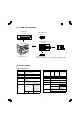
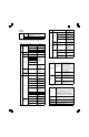
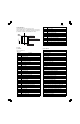
AR-PB8 [1] SYSTEM CONFIGURATION LCD panel kit (AR-PA1) PS2 expansion kit (AR-PS1) Printer expansion kit (AR-PB8) Print server card Expansion memory (Commercially available 168 pin EDO DIMM: 16MB/32MB/64MB) AR-160/200 Series [2] SPECIFICATIONS 1. Basic specifications Item Contents Item Contents Paper size 600 dpi, 300 dpi (1,200 dpi equivalent by smoothing) 11" × 17", 8.5" × 14", 8.5" × 11", 8.5" Tray 1 ∼ 4∗ Inch series × 11"R, 8.5" × 5.5", 8.
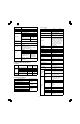
AR-PB8 Item C. Set content Contents Interface select Auto Emulation select Auto Plug and play Conforming (only with Windows 95/98) Item ∗A Microsoft Windows 3.1 Microsoft Windows 98 Orientation Portrait, Landscape Document Style 1-Sided, 2-Sided(Book), 2-Sided(Tablet)∗B Paper Source Auto, Tray 1, Tray 2, Tray 3, Tray 4, Bypass Tray Paper Size A3 (297 × 420 mm), B4 (257 × 364 mm), A4 (210 × 297 mm), A5 (148 × 210 mm), B5 (182 × 257 mm), Ledger (11" × 17"), Letter (8.5" × 11"), Legal (8.
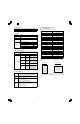
AR-PB8 D. Option Status LCD display (1) LCD kit AR-PA1 Key 6 pcs. (LINE, MENU, ITEM, ←, →, ENTER) Lamp 2 (DATA, ONLINE) Display 20 digits × 2 lines Network Menu ∗1 ∗ When installing the AR-PB8 to a model which is not equipped with the LCD panel, the LCD kit (AR-PA1) must be installed to. a.
AR-PB8 (2) Network board G. Paper handling specifications 10/100 Base TX TCP/IP, IPX/SPX, Ether Talk, Jet Admin∗A 10 Base 2/T TCP/IP, IPX/SPX, Ether Talk, Jet Admin∗A (1) Paper feed direction a.
AR-PB8 a. Tablet operation Tablet means printing so that each page is aligned to be read properly when binding the short edge of paper. Therefore, the front page (odd number page) and the back page (even number page) are in upside down each other. This reversion is mechanically made, and the printer software needs no additional process.
AR-PB8 H.
AR-PB8 I. Print reference Font No. This machine employs the center reference system. Since the digital copier is not equipped with the paper size detection, format is made not by the actual paper size but by the paper size specified by the computer, and center distribution is made.
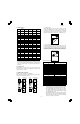
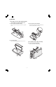
AR-PB8 [3] SET UP 1. Procedures on the copier (operation panel) ∗ When installing the LCD panel kit simultaneonsly. A. Copier operation panel disassembly • Remove screws and connector, and remove C. Printer operation panel installation • Engage pawls and fix the printer operation panel with screw. the operation panel. Then connect the flat cable to the connector. B. Cover disassembly • Remove screw and disengage pawls, and remove the cover. 2. Procedures on the copier (rear side) A.
AR-PB8 B. Copier shield plate disassembly • Remove screws, and remove the shield plate. D. Printer PWB installation • Fix the printer PWB with screws. • Before introduction of the Expansion memory, the PS PWB, or the network PWB, this procedure must be performed. E. Mother board installation (Packed together with the LCD kit.) • Insert the connectors and fix them, then connect the connectors of the copier to them. C. PWB fixing plate installation • Fix the plate with screws. F.
AR-PB8 G. PWB cover installation • Install the PWB cover with screws. 4. PS kit (AR-PS1) installation • Fix the PS PWB with pawl. ∗Note: The DIMM connector and the PS-PWB are provided with the reverse insertion protection key(notch). A strong push, however, allows reverse insertion. Use great care of the inserting direction. 3. Expansion memory installation • Fix the memory PWB with pawls. 5.
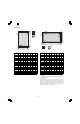
AR-PB8 • 6. INSTALLING THE PRINTER DRIVER To use this printer with your computer, you must install the printer driver. Install the printer driver using the supplied SHARP Software CDROM. This kit is supplied with the following printer drivers: • PCL6 for Windows 95/98 • PCL6 for Windows NT 4.0 • PCL5e for Windows 95/98 • PCL5e for Windows NT 4.0 Note: • It is recommended that you install the PCL6 printer driver.
AR-PB8 6) Print a test page by clicking the [Finish] button. Note: If you check “No” and click the [Finish] button, the printer does not print a test page after the installation. • The printer driver installation begins. 3) Click the [Have Disk...] button. 4) Insert the SHARP Software CD-ROM into the CD-ROM drive, type R:\English\WinXX, and click the [OK] button. • If the “Insert Disk” window appears, perform the following steps: <1> Click the [OK] button.
AR-PB8 C. Installing onto Windows 95/98 without Using the Plug & Play Function Computers using Windows 95 or Windows 98 that are compatible with plug & play can install the printer driver automatically. However, if your computer is incompatible with plug & play, or if you want to use this printer as a network printer, follow the procedure in this section. The following steps use Windows 98 in display examples. 1) Turn the computer on and start Windows 95/98.
AR-PB8 D. Installing onto Windows NT 4.0 1) Turn the computer on and start Windows NT. 2) Click the Start menu, point to “Settings”, and choose “Printers”. 3) When the “Printers” window appears, double-click the “Add Printer” icon. 4) Choose “My Computer” or “Network printer server” and click the [Next] button. • The following steps use “My Computer” as an example. For more information about using this printer as a network printer, refer to the Windows NT 4.0 networking documentation.
AR-PB8 [4] SETTING AND ADJUSTMENTS 1.
AR-PB8 4) Press the Left or Right arrow key to change the setting. • The current value is marked with an asterisk (∗). Item DATA LINE MENU ITEM ENTER Paper Size 5) After choosing the required value, press the ENTER key. • The new value is registered. Orientation DATA NE MENU ITEM ENTER Emulation Possible Settings A3 B4 A4∗ B5 A5 Ledger Legal Letter∗ Executive Folio Invoice Foolscap COM-10 DL C5 Description Sets the size of the paper where data will be printed.
AR-PB8 [5] SIMULATION 1. Entering the simulation mode Perform the following procedure to enter the simulation mode. Clear key → Interruption key → “0” key → Interruption key → Main code → Start key → Sub code → Start key 2. Cancelling the simulation mode When the all clear key is pressed, the simulation mode is cancelled. When the interruption key is pressed, the process is interrupted and the screen returns to the sub code entering display. 3.
AR-PB8 [6] CONFIGURATION REPORT AND TEST PAGE To test print the configuration page and font list, use the following procedure: 1) Press the ON LINE key to switch the printer to the offline mode. 3) Press the ITEM key to display the required item. DATA DATA ON LINE MENU ON LINE ENTER ITEM 2) Press the MENU key to display the Test Menu. ITEM 4) Press the ENTER key. The test page prints. DATA ON LINE MENU DATA MENU ITEM ENT NE MENU 1.
AR-PB8 Available Paper Size 2. Items and contents Appearance on Configuration Page A. Hardware status (Machine information) a. Language Value: (English/French/German/Italian/Dutch/Spanish/Swedish) Example: English Default: Depends on the Destination setting Description: Depends on the LCD display, the configuration page, and the font list language.
AR-PB8 [7] FIRMWARE VERSION UP 1. Cases where flash memory rewriting is required In the following cases, the program in the printer control PWB flash memory must be rewritten. 1) When a bug or other error is found 2) Data stored in the flash memory is destroyed or deleted. 3) When the flash memory is replaced. 2. Necessary tools 1) Computer (PC) 2) Parallel cable 3) Program data file (xxx.BIN) 3. Procedure 1) Print the configuration list to check the firmware version.
AR-PB8 [8] TROUBLE CODE LIST Main Sub code code F9 00 Content Detail Cause Check and remedy 10 Content Detail Cause Check and remedy 80 Content Detail Cause Check and remedy 81 Content Detail Cause Check and remedy Main Sub code code F9 82 Content Detail of trouble F9-∗∗∗ Communication trouble between MCU and PRT.
AR-PB8 [9] CIRCUIT DIAGRAM 1. BLOCK DIAGRAM 14.318MHz PDATA[7:0] SCLK PARACONN MODECLK 22.22MHz MODEIN G/A (2) 44.44MHz MASTERCLK SYSAD[15:0] MODEIN CY2292 14.
AR-PB8 AR-PB8 2. CIRCUIT DIAGRAM A C B E D CPU SYSAD[63:0] 3.3V IC1 R114 R113 R112 R115 R116 R117 R118 R119 R120 4 SYSCMD[8:0] R173 R199 R305 R252 R174 R200 R306 R253 3.3V 4.7K 4.7K 4.7K 4.7K 4.7K 4.7K 4.7K 4.7K 4.7K SYSCMD0 SYSCMD1 SYSCMD2 SYSCMD3 SYSCMD4 SYSCMD5 SYSCMD6 SYSCMD7 SYSCMD8 3.3V R69 R67 R102 R222 R304 4.7K 4.7K 4.7K 4.7K 4.7K 3 R135 R161 R134 R162 R136 R163 R137 R164 R165 SYSADC0 SYSADC1 SYSADC2 SYSADC3 SYSADC4 SYSADC5 SYSADC6 SYSADC7 10 10 10 10 10 10 10 10 10 R175 3.3V 4.
AR-PB8 A AR-PB8 C B E D ASIC 1 SYSCMD[8:0] SYSCMD0 SYSCMD1 SYSCMD2 SYSCMD3 SYSCMD4 SYSCMD5 SYSCMD6 SYSCMD7 SYSCMD8 4 120 10 107 10 106 10 105 119 VALOUT_ VALIN_ READY_ EXREQ_ RLS_ R73 R72 R71 INTR0_ INTR1_ INTR2_ NMI_ R70 R68 R103 R101 VCCOK COLDRES_ CPURES_ R100 R99 R98 10 10 10 10 104 103 102 101 INTR0_ INTR1_ INTR2_ NMI_ VCCOK CRST_ CPURST_ 118 R94 257 SYNCEN_ VFCLK SYNCEN_ 262 VFCLK HSYNC_ PAGE_ VDIN_ R95 R96 265 267 HSYNC_ PAGE_ 268 VDATA_ 10 10 74LVC08 4 4.7K 4.7K 4.
AR-PB8 A AR-PB8 C B E D ASIC 2 SV R126 R127 R128 R129 4 4 R176 56 57 10 PARREQ_ PD ACK_ PDREQ_ R223 7 10 PARINTR_ CPUINTR_ 1.2K 1.2K 1.2K 1.
AR-PB8 A B AR-PB8 C D E MEMORY BUFFER SYSAD[63:0] MBA[11:0] RAD[21:1] 3.
AR-PB8 A AR-PB8 B C D E ROM SYSAD[63:0] RAD[21:1] IC2 RAD1 RAD2 RAD3 RAD4 RAD5 RAD6 RAD7 RAD8 RAD9 RAD10 RAD11 RAD12 RAD13 RAD14 RAD15 RAD16 RAD17 RAD18 RAD19 RAD20 RAD21 4 3.
AR-PB8 A AR-PB8 B C D E DRAM MBA[11:0] MD[63:0] CN3 IC6 MBA0 MBA1 MBA2 MBA3 MBA4 MBA5 MBA6 MBA7 MBA8 MBA9 MBA10 MBA11 4 RAS0_ CAS0_ CAS1_ MBWE_ MBOE_ 3.3V 17 18 19 20 23 24 25 26 27 28 16 15 14 31 30 13 29 32 1 6 21 A0 A1 A2 A3 A4 A5 A6 A7 A8 A9 A10 A11 RAS_ LCAS_ UCAS_ WE_ OE_ NC Vcc Vcc Vcc 16M16 3 CAS2_ CAS3_ TITLE 3.
AR-PB8 A AR-PB8 B C D E CONNECTOR & EET R17 R16 R15 R14 R13 CPWBX0034QS51 2.2K 2.2K 2.2K 2.2K 2.2K 2 4 6 8 11 13 15 17 PREADY_ PAGE_ SRDY_ CMD VDATA_ 1A1 1A2 1A3 1A4 2A1 2A2 2A3 2A4 1 19 1G 2G 1Y1 1Y2 1Y3 1Y4 2Y1 2Y2 2Y3 2Y4 VCC GND 18 16 14 12 9 7 5 3 R1 R2 R3 R4 R5 20 10 25 10 27 11 14 10 10 10 10 10 C26 C25 C24 C23 C22 100p 100p 100p 100p 100p PCLREADY_ RESET_ PCLPAGE_ HSYNC_ PCLSRDY_ READY_ PCLCMD PCLCRDY_ PCLPRD_ PCLSTS 7 8 23 12 26 5V 3.
AR-PB8 COPYRIGHT © 1999 BY SHARP CORPORATION All rights reserved. Printed in Japan. No part of this publication may be reproduced, stored in a retrieval system, or transmitted, in any form or by any means, electronic, mechanical, photocopying, recording, or otherwise, without prior written permission of the publisher.