MODEL AR-M162 AR-M207 DIGITAL MULTIFUNCTIONAL SYSTEM OPERATION MANUAL (for general information and copier) Page PART 1: GENERAL INFORMATION • BEFORE USING THE PRODUCT • TROUBLESHOOTING AND MAINTENANCE • PERIPHERAL DEVICES AND SUPPLIES 12 24 40 PART 2: COPIER OPERATION AR-M162 • COPY FUNCTIONS • CONVENIENT COPY FUNCTIONS • APPENDIX 45 64 73 Be sure to become thoroughly familiar with this manual to gain the maximum benefit from the product.
Caution: For complete electrical disconnection, pull out the main plug. The socket-outlet should be installed near the equipment and should be easily accessible. FOR YOUR RECORDS ... To protect against loss or theft, record and retain for reference the machine's serial number located on the back of the unit.
Part 1: General Information 1
2
Notes • Considerable care has been taken in preparing this manual. If you have any comments or concerns about the manual, please contact your nearest SHARP Service Department. • This product has undergone strict quality control and inspection procedures. In the unlikely event that a defect or other problem is discovered, please contact your dealer or nearest SHARP Service Department.
CONTENTS Part 1: General Information PRODUCT CONFIGURATIONS ................................................................................................................ 3 CAUTIONS................................................................................................................................................. 6 ● CAUTIONS ON USING..................................................................................................................................... 6 ● LASER INFORMATION ......
CONTENTS Part 2: Copier Operation 4 COPY FUNCTIONS NORMAL COPYING ........................................ 45 ● ● ● ● ● 6 APPENDIX SPECIFICATIONS ........................................... 73 MAKING A COPY DARKER OR LIGHTER ....48 SELECTING THE TRAY.................................49 SETTING THE NUMBER OF COPIES ...........49 SELECTING THE ORIGINAL SIZE ................50 USING THE BYPASS TRAY TO COPY A SPECIAL SIZE ORIGINAL..............................51 MATERIAL SAFETY DATA SHEET...............
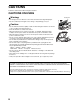
CAUTIONS Follow the cautions below when using this machine. CAUTIONS ON USING Warning: Fusing unit • The fusing area is hot. Exercise care in this area when removing misfed paper. • Do not look directly at the light source. Doing so may damage your eyes. Caution: • Do not switch the machine rapidly on and off. After turning the machine off, wait 10 to 15 seconds before turning it back on. • Place the machine on a firm, level surface.
CAUTIONS LASER INFORMATION Wave length 785 nm +10 nm -15 nm Pulse times North America: (3.1 µs ± 3.1 ns)/7 mm Europe: (3.7 µs ± 3.7 ns)/7 mm Output power Max 0.8 mW At the production line, the output power of the scanner unit is adjusted to 0.8 MILLIWATT PLUS 10 % and is maintained constant by the operation of the Automatic Power Control (APC). Caution Use of controls or adjustments or performance of procedures other than those specified herein may result in hazardous radiation exposure.
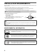
INSTALLATION REQUIREMENTS Improper installation may damage this product. Please note the following during initial installation and whenever the machine is moved. 1. The machine should be installed near an accessible power outlet for easy connection. 2. Be sure to connect the power cord only to a power outlet that meets the specified voltage and current requirements. Also make certain the outlet is properly grounded. • For the power supply requirements, see the name plate on the back of the main unit.
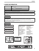
MANUALS PROVIDED WITH THE PRODUCT Multiple manuals are provided for use of the machine. Please read each manual as appropriate for the functions that you wish to use. Operation manual (for general information and copier) (this manual): The first half of this manual contains general information on the machine, including safety precautions and the procedures for loading paper, removing misfeeds, and performing regular maintenance.
MAIN FEATURES High-speed laser copying • First-copy time*1 at 300 dpi*2 is only 7.2 seconds. • Copying speed is 20 (AR-M207) or 16 (AR-M162) copies per minute. This provides a big boost to workplace productivity. *1 Measured after the machine has warmed up following power-on, copying using the document glass (8-1/2" x 11" (A4) paper fed from machine tray 1). The first-copy time may vary depending on machine operating conditions and ambient conditions such as temperature and power voltage.
MAIN FEATURES Fax function (option) Installation of the optional facsimile expansion kit enables the plain-paper, Super G3 laser fax function to be used. Network connection (option) The optional network expansion kit (AR-NB3) can be installed to enable the machine to be used as a network printer and network scanner. Environment and people friendly design • Preheat and auto power shut-off modes are provided to reduce power consumption when the machine is not in active use.
1 BEFORE USING THE PRODUCT This chapter contains basic information required for use of the machine. Please read this chapter before using the machine. PART NAMES AND FUNCTIONS (5) (15) (10) (11) (9) (1) (6) (2) (7) (3) (7) (8) (17) (14) (1) USB 2.0 port (USB-2) (when the dual function board is installed) Connect to your computer to this port to use the printer and scanner functions. (2) USB 1.1 port (USB-1) Connect to your computer to this port to use the printer and scanner functions.
BEFORE USING THE PRODUCT (23) (24) (25) (29) (30) (26) 1 (21) (28) (31) (27) (32) (22) (15) Document cover (when installed) Open to make a copy from the document glass. (26) Right side cover (when the SPF is installed) Open to remove misfed originals. (16) Side cover Open to remove misfed paper. (27) Fusing unit release levers To remove the paper misfed in the fusing unit, push down on these levers and remove the paper. (17) Side cover handle Pull to open the side cover.
BEFORE USING THE PRODUCT OPERATION PANEL (1) (2) (3) (4) 26 27 28 29 41 30 42 43 44 45 COPY A 31 B 32 F 36 G 37 K C 33 H 38 L D 34 I 39 M E J 40 N P 46 35 Q 47 U R 48 V W SPEAKER REDIAL/PAUSE O SHIFT S 49 T 50 XYZ SP SPEED COMM. SETTING SYMBOL SPACE/– ON LINE DATA PRINT SCAN LINE DATA FAX (13) (1) Keys for fax function (when the fax option is installed) These are used in fax mode.
BEFORE USING THE PRODUCT (5) (6) (7) (8) (9) (10) (11) (12) FAX STATUS BACK COPY EXPOSURE PAPER ZOOM OK ABC DEF GHI JKL MNO PQRS TUV WXYZ AUTO % OUTPUT DUPLEX @.-_ SPECIAL FUNCTION SCAN COLOR MODE RESOLUTION ADDRESS FORMAT ORIGINAL SIZE DUPLEX SCAN FAX PROGRAM RESOLUTION ADDRESS BROADCAST ORIGINAL SIZE DUPLEX SCAN (15) (16) (17) (18) (19) (20) (21) (22) (23) (13) LINE STATUS indicator (when the fax option is installed) This key is used in fax mode.
BEFORE USING THE PRODUCT Display (base screen) Example: Copy mode (1) (2) Icons appearing in the special function icon display (3) (4) Ready to copy. 812 x11 AUTO 100% 812 x11 (5) AUTO (6) (7) * The display shown is the AR-M207 (when the optional RSPF is installed) display.
TURNING THE POWER ON AND OFF The power switch is located on the left side of the machine. POWER ON POWER OFF Turn the power switch to the "ON" position Make sure that the machine is not in operation and then turn the power switch to the "OFF" position. • It will take about 45 seconds for the machine to warm up. • When the power switch is turned to the "ON" position, the message "System check." will appear in the message display and warm-up will start.
BEFORE USING THE PRODUCT Default settings The machine is set at the factory to return all settings to the default settings one minute after a copy job is finished (auto clear function) or when the [CA] key is pressed. When the settings return to the default settings, any functions that were selected are canceled. The auto clear time can be changed in the key operator programs. (See the "Key operator's guide".) In the default state the display shown below appears.
BEFORE USING THE PRODUCT Special paper Follow these guidelines when using special paper. • Use SHARP recommended transparency film and label sheets. Using other than SHARP recommended paper may result in misfeeds or smudges on the output. • There are many varieties of special paper available on the market, and some cannot be used with this machine. Before using special paper, contact a SHARP service center. • Before using other than SHARP recommended paper, make a test copy to see if the paper is suitable.
BEFORE USING THE PRODUCT Loading paper in the bypass tray 1 Open the bypass tray. Important points when inserting paper in the bypass tray • Up to 100 sheets of standard copy paper can be set in the bypass tray. • Be sure to place 5-1/2" x 8-1/2" (A6 and B6) size paper and envelopes horizontally as shown in the following diagram. Pull out the bypass tray extension to load 8-1/2" x 14" and 11" x 17" (B4 and A3) size paper. 2 Set the bypass tray guides to the paper width.
BEFORE USING THE PRODUCT CHANGING THE PAPER SIZE SETTING OF A TRAY If the size of the loaded paper is different from the size shown in the display, follow the steps below to change the paper size setting of the tray. The paper size setting cannot be changed during copying, printing, fax printing (when the fax option is installed), or interrupt copying, or when a misfeed has occurred.
BEFORE USING THE PRODUCT DISABLING (ENABLING) AUTO TRAY SWITCHING When auto tray switching is enabled and paper runs out during copying or printing, the job will continue using paper from a different tray if that tray has the same size of paper in the same orientation. (This function does not operate when using the bypass tray or when a fax is being printed.) This function has been enabled at the factory. If you prefer to disable the function, follow the steps below. 1 Press the [SPECIAL FUNCTION] key.
AUDITING MODE When auditing mode is enabled, a count is kept of the pages printed by each account. The page counts can be viewed in the display. This function is enabled in the key operator programs. (For the counts in copy, print, and scan modes, see the "Key operator's guide". For the counts in fax mode, see the "Operation manual (for facsimile)" that accompanies the optional facsimile expansion kit.
2 TROUBLESHOOTING AND MAINTENANCE This chapter explains general troubleshooting and maintenance procedures such as removing misfeeds, replacing the toner cartridge, and cleaning the machine, as well as troubleshooting for the copy function. For troubleshooting for the fax function, printer function, and scanner function, see the respective manuals for each function. TROUBLESHOOTING MACHINE/COPYING PROBLEMS The machine does not operate. .....................................................................
TROUBLESHOOTING MACHINE/COPYING PROBLEMS Check the following troubleshooting list before requesting service as many problems can be fixed by the user. If you are unable to solve the problem by checking the list, turn off the power switch, unplug the power cord. Problems related to general use of the machine and copying are described below. If a problem occurs in printer or scanner mode, see the "Operation manual (for printer and scanner)".
TROUBLESHOOTING AND MAINTENANCE Problem Cause and solution The original was placed in the wrong position. → Place the original correctly. The paper size used for the copy is different from the selected paper size (part of the image is cut off or too much of the page is blank). An appropriate ratio was not used for the size of the original and the size of the paper. → Press the [AUTO%] key to select the appropriate copy ratio based on the original and copy sizes.
TROUBLESHOOTING AND MAINTENANCE Problem Cause and solution Was the SPF (or document cover) opened completely when the original was placed on the document glass? → Open the SPF completely and then place the original on the document glass. Close the SPF (or document cover). Page 45 The original is curled or folded. → The original size cannot be correctly detected if the original is curled or folded. Straighten the original. – The original has many solid black areas.
INDICATORS AND DISPLAY MESSAGES If one of the following messages appears in the display, take prompt action as instructed by the message. Message Action (Maintenance icon) It is time for regular maintenance. Contact your SHARP service center. (Developer replacement required icon) Developer is required. Contact your SHARP service center as soon as possible. Maintenance required. Call for service. Maintenance required soon. Contact your SHARP service center. Call for service.
REMOVING MISFEEDS When a misfeed occurs during copying, the message " Check the location and remove the misfeed. Note Clear paper path." and the location of the misfeed will appear. The paper may tear when you remove a misfeed. In this event, be sure to remove all torn pieces of paper from the machine, taking care not to touch the photoconductive drum (the green part). Any scratches or damage to the surface of the drum will cause dirty copies. First check the misfeed location.
TROUBLESHOOTING AND MAINTENANCE 2 Open and close the SPF. Opening and closing the cover clears the misfeed display. Copying cannot be resumed until this step is performed. A message may appear indicating the number of originals which must be returned to the document feeder tray. Return the originals to the document feeder tray and press the [START] key ( ). MISFEED IN THE BYPASS TRAY 1 Carefully remove the misfed paper from the bypass tray.
TROUBLESHOOTING AND MAINTENANCE MISFEED IN THE MACHINE To remove a paper misfeed from the machine, the bypass tray and then the side cover must be opened. Check whether the misfeed occurred in A, B, or C below and then follow the misfeed removal procedure for that location. 1 Open the bypass tray and then the side cover. 2 Determine where the misfeed occurred. Location B If paper is misfed here, go to "Misfeed in B" (page 32). Location C If paper is misfed here, go to "Misfeed in C" (page 33).
TROUBLESHOOTING AND MAINTENANCE Misfeed in B 1 Open the front cover. 4 Lift the fusing unit release levers. 5 Close the front cover and the side cover. Push gently on both ends of the front cover. 2 Turn the roller rotating knob in the direction of the arrow. The message " Clear paper path." will be cleared and copying will be possible. Roller rotating knob 3 Lower the right and left fusing unit release levers and remove the misfed paper.
TROUBLESHOOTING AND MAINTENANCE Misfeed in C 1 Lower (1) in the illustration, open the fusing unit paper guide, and remove the misfed paper. 3 Close the side cover. The message " Clear paper path." will be cleared and copying will be possible. Be careful not to tear the misfed paper during removal. (1) Warning 2 Note The fusing unit is hot. Do not touch the fusing unit when removing misfed paper. Doing so may cause a burn or injury. • When closing the side cover, hold the handle.
TROUBLESHOOTING AND MAINTENANCE MISFEED IN TRAY 2 Note 1 • Make sure that there is no misfed paper in the tray before pulling it out. (Page 31) • Also use the following procedure to remove misfeeds that occur in the 250-sheet paper feed unit and the 2 x 500-sheet paper feed unit. Open the side cover. Grasp the handle to open the side cover. 5 Gently push tray 2 into the machine. Push the tray in completely. Side cover 2 Remove the misfed paper.
REPLACING THE TONER CARTRIDGE When the toner replacement icon ( ) appears, little toner remains. Obtain a replacement cartridge as soon as possible. When the message " Add toner. Can not copy or print." appears in the display, the toner cartridge must be replaced before copying can be resumed. Follow the steps below to replace the toner cartridge. Note 1 • During a long copy run or when copying originals with many dark areas, the message "Toner replenishment in progress.
CHECKING THE TOTAL OUTPUT COUNT To check the total number of pages output in copy, print, and fax modes and the total scan count in scanner mode, hold down the [COPY] key when the machine is in the standby state. The counts will appear while the key is held down. The total output count and the total scan count can be used as a guideline for cleaning. When the total output count and the total scan count exceed "999,999", the counts return to "0".
CLEANING THE MACHINE CLEANING THE DOCUMENT GLASS AND SPF/DOCUMENT COVER If the document glass, SPF, underside of the document cover, or the scanner for originals coming from SPF (A) (the long narrow glass surface on the right side of the document glass) become dirty, the dirt may appear on copies. Always keep these parts clean. (A) Wipe with a clean, soft cloth. If necessary, moisten the cloth with water or a small amount of neutral detergent. When finished, wipe dry with a clean cloth.
TROUBLESHOOTING AND MAINTENANCE CLEANING THE TRANSFER CHARGER If white or black lines appear in copies or the image is blotchy, the transfer charger may be dirty. Follow the steps below to clean the charger. 1 Turn the power switch off. 5 Place the charger cleaner on the transfer charger and gently slide the cleaner in the direction indicated by the arrow two or three times. If the sheet metal on the transfer charger is smudged with toner, wipe it with a soft, clean cloth.
ADJUSTING THE DISPLAY CONTRAST The contrast of the display can be adjusted as explained below. 1 Press the [SPECIAL FUNCTION] key. DUPLEX SPECIAL FUNCTION DUPLEX SCAN DUPLEX SCAN ACC. The special function screen will appear. SPECIAL FUNCTION SPECIAL MODES ORIG. SIZE ENTER PAPER SIZE SET DISPLAY CONTRAST 4 Adjust the contrast with the [ ] or [ ] key. To reset the contrast to the default setting, press the [C] key. 5 Press the [SPECIAL FUNCTION] key.
3 PERIPHERAL DEVICES AND SUPPLIES Optional equipment and supplies are explained in this chapter. To purchase optional equipment and supplies, contact your dealer or SHARP service. OPTIONAL EQUIPMENT Convenient optional equipment can be installed on the machine as needed. Note • As a part of our policy of continuous improvement, SHARP reserves the right to make design and specification changes for product improvement without prior notice.
PERIPHERAL DEVICES AND SUPPLIES REVERSING SINGLE PASS FEEDER / SINGLE PASS FEEDER For the names of the parts of the RSPF / SPF, see "PART NAMES AND FUNCTIONS" (page 12). Specifications Model AR-SP6N Acceptable originals AR-RP6N Weight 15 lbs. to 24 lbs.
PERIPHERAL DEVICES AND SUPPLIES DUAL FUNCTION BOARD A dual function board can be installed to add a variety of copy functions and enable use of the printer driver for the dual function board, which is a more advanced printer driver than the standard printer driver. For copy functions that can be used, see "CONVENIENT COPY FUNCTIONS" (page 64). Specification Model AR-EB9 Added functions Sort copy, 2 in 1 / 4 in 1 copying, rotation copy, border erase copying, margin copying, card shot, USB 2.
Part 2: Copier Operation 43
44
4 COPY FUNCTIONS This chapter explains the basic procedures for making copies, including selection of the copy ratio and other copy settings. NORMAL COPYING This section explains how to make a regular copy. If "Auditing mode" has been enabled (page 23), enter your 5-digit account number. Copying from the document glass 1 Open the SPF and place the original face down on the document glass. Align the upper left-hand corner of the original with the tip of the mark.
COPY FUNCTIONS 5 Press the [START] key ( copying. WXYZ ) to begin Note The copy will be delivered to the center tray. @.-_ READ-END • The center tray can hold a maximum of 250 sheets (150 sheets when the job separator tray kit is installed). • About one minute after copying ends, "Auto clear" (page 18) activates and restores the copy settings to the default settings. The setting for "Auto clear" can be changed in the key operator programs. (See the "Key operator's guide".
COPY FUNCTIONS Auto paper select mode When auto paper select mode is enabled, "AUTO" appears in the paper size display. This function automatically selects paper that is the same size as the original (5-1/2" x 8-1/2", 8-1/2" x 11", 8-1/2" x 11"R, 8-1/2" x 13", 8-1/2" x 14", 11" x 17", A5, B5, B5R, A4, A4R, B4, A3 paper). • If a zoom setting is selected after placing the original, the paper size that is appropriate for the zoom setting will be automatically selected.
COPY FUNCTIONS MAKING A COPY DARKER OR LIGHTER The copy exposure can be adjusted as needed to the original. Three exposure modes are available: "AUTO", "TEXT" and "PHOTO". When "TEXT" or "PHOTO" is selected, the exposure can be manually adjusted to 5 levels. Auto This is the default exposure mode. In this mode, the characteristics of an original being copied are "read" by the exposure system and exposure adjustments are made automatically.
COPY FUNCTIONS SELECTING THE TRAY By default the auto paper select function (page 47) operates, and thus the appropriate tray is automatically selected when the original is placed on the document glass or in the document feeder tray, or when the original size is specified. If you wish to use a tray other than the automatically selected tray (for example you wish to enlarge or reduce the copy or use the bypass tray), press the [PAPER] key to select the desired tray.
COPY FUNCTIONS SELECTING THE ORIGINAL SIZE If you loaded a non-standard size* original or the original size was not correctly detected, set the original size manually. Perform the following steps after placing the document in the document feeder tray or on the document glass. Note 1 * Standard sizes: The following sizes can be detected correctly: 11" x 17", 8-1/2" x 14", 8-1/2" x 11", 8-1/2" x 11"R, 5-1/2" x 8-1/2" (A3, B4, A4, A4R, A5).
COPY FUNCTIONS USING THE BYPASS TRAY TO COPY A SPECIAL SIZE ORIGINAL When the bypass tray is being used for copying and an original that is placed on the document glass is detected as being a special size, the display will prompt the user to set the original size. To make a copy in this type of situation, follow the steps below. 1 2 POSURE Load paper in the bypass tray and place the original on the document glass. Press the [OK] key.
REDUCING OR ENLARGING A COPY There are three ways to enlarge and reduce copies: • Automatic selection of a ratio according to the paper size: Auto ratio selection • Specifying a ratio from 25% to 400%: Preset ratios/zoom • Selecting the vertical and horizontal ratios separately: XY zoom Note When the SPF is being used, the zoom copy ratio range is 50% to 200%. AUTOMATIC RATIO SELECTION 1 Place the original in the document feeder tray or on the document glass. 3 PER Press the [AUTO%] key.
COPY FUNCTIONS 3 Select a preset ratio with the [ ] or [ ] key, or set the ratio (zoom) with the [ ] or [ ] key. GH 4 Press the [OK] key. BACK You will return to the base screen. OK PQR GHI DUPLEX SPECIAL FUNCTION DUPLEX SCAN [ [ [ [ ] key: Select a larger preset ratio ] key: Select a smaller preset ratio ] key: Decrease the ratio in increments of 1% ] key: Increase the ratio in increments of 1% • Preset reduction ratios are: 95%, 77%, 64%, 50% and 25% (86%, 81%, 70%, 50% and 25%).
SELECTING THE VERTICAL AND HORIZONTAL COPY RATIOS SEPARATELY (XY zoom copying) Separate ratio settings can be selected for the length and width of a copy. Example: Reduction only in the horizontal direction Original Copy • This feature cannot be used with the 2 in 1 / 4 in 1 feature or card shot feature (when the dual function board is installed). • To use the XY zoom feature and the dual page copy feature simultaneously, set the dual page copy feature first and then the XY zoom feature.
COPY FUNCTIONS 7 Press the XY ZOOM 121% ZOOM 100% X: 121% 95% Y: 100% [ ]:X Y @.-_ FUNCTION ACC. #-C 11 key. READ-E Select any other copy settings as needed and press the [START] key ( ). WXYZ @.-_ READ-END The vertical ratio can now be selected. 8 Set the vertical ratio with the [ ], [ ], [ ], or [ ] keys. A preset ratio can be selected with the [ ] or [ ] keys. The ratio can be adjusted in increments of 1% with the [ ] or [ ] keys.
TWO-SIDED COPYING TWO-SIDED COPYING The machine is capable of the following types of automatic two-sided copying. The copy paper is turned over automatically, allowing two-sided copying to be accomplished with ease.
COPY FUNCTIONS TWO-SIDED COPYING OF ONE-SIDED ORIGINALS • Paper sizes that can be used are 11" x 17", 8-1/2" x 14", 8-1/2" x 13", 8-1/2" x 11", 8-1/2" x 11"R, A3, B4, A4, A4R, B5, B5R and A5. • Automatic two-sided copying is not possible when the bypass tray is used. Copying from the SPF 1 Make sure that an original does not remain on the document glass, and then adjust the original guides to the width of your originals and place the originals face up in the document feeder tray.
COPY FUNCTIONS Copying from the document glass 1 Place the original for the front side of the copy on the document glass, and close the SPF. 6 Make sure that the desired paper tray is selected. 7 Set the number of copies and press the [START] key ( ). WXYZ 2 Press the [DUPLEX] key.
COPY FUNCTIONS TWO-SIDED COPIES OF TWO-SIDED ORIGINALS (ONLY WHEN USING THE RSPF) • Paper sizes that can be used are 11" x 17", 8-1/2" x 14", 8-1/2" x 13", 8-1/2" x 11", 8-1/2" x 11"R, A3, B4, A4, A4R, B5, B5R and A5. • Automatic two-sided copying is not possible when the bypass tray is used. • This copy function cannot be used in combination with dual page copy.
COPY FUNCTIONS ONE-SIDED COPIES OF TWO-SIDED ORIGINALS (ONLY WHEN USING THE RSPF) • Paper sizes that can be used are 11" x 17", 8-1/2" x 14", 8-1/2" x 13", 8-1/2" x 11", 8-1/2" x 11"R, A3, B4, A4, A4R, B5, B5R and A5. • Automatic two-sided copying is not possible when the bypass tray is used. • This copy function cannot be used in combination with dual page copy.
TWO-SIDED COPIES USING THE BYPASS TRAY Follow the steps below to perform two-sided copying manually. Example: Copying original A and original B onto both sides of the paper 1 1 2 1 If you are using the AR-M207 The AR-M207 is equipped standard with an automatic two-sided copying function that automatically turns over the paper. If paper in "Paper that can be used for automatic 2-sided printing" on page 18 is used, this enables easier two-sided copying than using the bypass tray.
DUAL PAGE COPY (Dual page copy) The dual page copy function produces separate copies of open bound original pages. This function is convenient when you wish to make a separate copy of each page of a book or other bound document. Original • • • • 8-1/2" x 11" (A4) paper can be used for dual page copying. When rotation copy is enabled, 8-1/2" x 11"R (A4R) paper can also be used. When used in combination with XY zoom copying, enlargement is not possible.
INTERRUPTING A COPY RUN (Interrupt copying) A copy run can be temporarily interrupted to allow another copy job to be performed. (Interrupt copying) When the other job is finished, the copy run will resume using the original copy settings. • Interrupt copying is not possible when the document glass is being used for a copy job and "NO SORT" is selected. • When 2 in 1 or 4 in 1 is selected, interrupt copying is not possible.
5 CONVENIENT COPY FUNCTIONS This chapter explains convenient copy functions that can be used when the dual function board (AR-EB9) is installed. Select convenient copy functions after pressing the [COPY] key to select copy mode.
CONVENIENT COPY FUNCTIONS 1 Place the originals in the document feeder tray or the first original on the document glass. If the originals are placed in the document feeder tray, sort mode will be automatically selected. This can be changed to no sort in the key operator programs. (See the "Key operator's guide".) If the first original is placed on the document glass, no sort mode will be automatically selected.
COPYING MULTIPLE ORIGINALS ONTO A SINGLE SHEET OF PAPER (2 in 1 / 4 in 1 copy) Multiple originals can be copied onto a single sheet of paper in a selected layout. This function is convenient when you wish to present multiple pages in a compact format, or show a view of all pages in a document. One of two layouts can be selected for 2 in 1 copy, and one of four layouts can be selected for 4 in 1 copy. Border line selections are solid line, broken line, or none.
CONVENIENT COPY FUNCTIONS 5 Select "2in1/4in1" with the [ ] or [ ] key. Select the borderline setting with the [ ] or [ ] key. SPECIAL MODES DUAL PAGE COPY 2in1/4in1 XY ZOOM [OK]:CHANGE GH PQR DUPLEX SPECIAL FUNCTION DUPLEX SCAN 6 10 2in1/4in1 OFF 2in1 4in1 [OK]:CHANGE The 2 in 1 / 4 in 1 selection screen will appear. BORDER Select solid line, broken line, or none. Press the [OK] key. OK 2in1 PATTERN 1 11 Press the [OK] key. OK 12 You will return to the base screen.
CREATING MARGINS WHEN COPYING (Margin shift) The margin shift function shifts the image to create a margin at the edge of the paper. By default the function creates a 1/2" (10 mm) margin at the left edge of the paper. Margin (top) Margin (left edge) A A A A Original Copy Original Copy • You can select whether to create a margin at the top edge or at the left edge of the paper. • Five selections are available for the margin width: 0", 1/4", 1/2", 3/4", 1" (0 mm, 5 mm, 10 mm, 15 mm, 20 mm).
ERASING SHADOWS AROUND THE EDGES OF A COPY (Erase copy) This feature is used to erase shadows that appear around the edges of copies of books and other thick originals. (Edge erase) The feature can also erase the shadow that appears down the center of books and other originals that open up. (Center erase) Both the shadow lines around the edges of copies and the shadow at the center can be erased.
CONVENIENT COPY FUNCTIONS 7 Select the erasure width with the [ ] or [ ] key. If you select 0" (0 mm), the printed result is the same as when "OFF" is selected. 8 Press the [OK] key. OK 9 Select other copy settings as needed and press the [START] key ( ). WXYZ @.-_ READ-END 70 You will return to the base screen. To cancel an edge erase setting, return to the edge erase settings screen and select "OFF".
CARD SHOT When copying a card, this function allows you to print the front and back sides of the card next to each other on a single sheet of paper. This function creates 2 in 1 images of the front and back side of the card and centers them on the paper. Original Copy CARD CARD Front of card Back of card CARD Example: Landscape 8-1/2" x 11" size Example: Portrait 8-1/2" x 11" size • Paper cannot be fed from the bypass tray.
CONVENIENT COPY FUNCTIONS 8 Press the [START] key ( WXYZ ). The front side of the card is scanned. @.-_ READ-END 9 Turn the original over on the document glass. 10 Press the [START] key ( ). Copying will start after both sides of the original have been scanned.
6 APPENDIX SPECIFICATIONS Name Digital Multifunctional System AR-M162 AR-M207 Type Desktop Photoconductive type OPC drum Document glass type Fixed Copy system Laser electrostatic method Originals Sheets, bound documents, max. original size 11" x 17" (A3) Copy sizes Max. 11" x 17" (A3), min. 5-1/2" x 8-1/2" (A5) (5-1/2" x 8-1/2" (A5) can only be fed from tray 1 and the bypass tray) Image loss: Max.
APPENDIX Overall dimensions 23-15/64" (W) x 23-7/16" (D) (590 mm (W) x 595 mm (D)) (with bypass tray folded) Weight Approx. 66.2 lbs. (30.0 kg) (Not including toner cartridge) Dimensions 23-15/64" (W) x 23-7/16" (D) x 18-15/32" (H) 23-15/64" (W) x 23-7/16" (D) x 20-31/64" (H) (590 mm (W) x 595 mm (D) x 469 mm (H)) (590 mm (W) x 595 mm (D) x 520 mm (H)) Operating conditions Temperature: 59°F to 86°F (15°C to 30°C), Humidity: 20% to 85% Noise level Sound Power Level LwA (1B=10dB) Copying: 6.
MATERIAL SAFETY DATA SHEET Page : 1/4 Date Revised : Aug.18, 2003 Date Issued : Jun. 1, 2003 MSDS No. F-01211 1.PRODUCT AND COMPANY IDENTIFICATION Product Name : AR-202NT / AR-202T / AR-202ST / AR-202FT / AR-202ST-C / AR-203ST-C / AR-016T/ AR-016ST / AR-016FT / AR-016RT (Black Toner) Supplier Identification : Sharp Corporation 22-22 Nagaike-cho, Abeno-ku, Osaka, Japan Local suppliers are listed below. Please contact the nearest supplier for additional information.
MATERIAL SAFETY DATA SHEET Page : 2/4 Date Revised : Aug.18, 2003 Date Issued : Jun. 1, 2003 MSDS No. F-01211 3.HAZARDS IDENTIFICATION Most Important Hazards and Effects of the Products Human Health Effects : There are no anticipated carcinogenic effects from exposure based on animal tests performed using toner. When used as intended according to instructions, studies do not indicate any symptoms of fibrosis will occur. Environmental Effects : No data are available.
MATERIAL SAFETY DATA SHEET Page : 3/4 Date Revised : Aug.18, 2003 Date Issued : Jun. 1, 2003 MSDS No. F-01211 Exposure Limit Values OSHA-PEL(USA) ACGIH-TLV(USA) Personal Protective Equipment Respiratory Protection Hand Protection Eye Protection Skin Protection Other Protective Equipment 3 : 15mg/m (Total Dust), 3 : 10mg/m (Total Dust), 3 5mg/m (Respirable Dust) 3 3mg/m (Respirable Dust) : Not required under intended use. : Not required under intended use. : Not required under intended use.
MATERIAL SAFETY DATA SHEET Chronic Effect Page : 4/4 Date Revised : Aug.18, 2003 Date Issued : Jun. 1, 2003 MSDS No.
MATERIAL SAFETY DATA SHEET Page : 1/4 Date Issued :Jun. 1, 2003 MSDS No. F-31211 1.PRODUCT AND COMPANY IDENTIFICATION Product Name Supplier Identification : AR-202ND / AR-202DV / AR-202SD / AR-202SD-C (Black Developer) : Sharp Corporation 22-22 Nagaike-cho, Abeno-ku, Osaka, Japan Local suppliers are listed below. Please contact the nearest supplier for additional information. Area (Country) (Name and Telephone Number) U.S.A.
MATERIAL SAFETY DATA SHEET Page : 2/4 Date Issued :Jun. 1, 2003 MSDS No. F-31211 3.HAZARDS IDENTIFICATION Most Important Hazards and Effects of the Products Human Health Effects : There are no anticipated carcinogenic effects from exposure based on animal tests performed using toner. When used as intended according to instructions, studies do not indicate any symptoms of fibrosis will occur. Environmental Effects : No data are available.
MATERIAL SAFETY DATA SHEET Page : 3/4 Date Issued :Jun. 1, 2003 MSDS No. F-31211 Exposure Limit Values OSHA-PEL(USA) ACGIH-TLV(USA) Personal Protective Equipment Respiratory Protection Hand Protection Eye Protection Skin Protection Other Protective Equipment 3 : 15mg/m (Total Dust), 3 : 10mg/m (Total Dust), 3 5mg/m (Respirable Dust) 3 3mg/m (Respirable Dust) : Not required under intended use. : Not required under intended use. : Not required under intended use. : Not required under intended use.
MATERIAL SAFETY DATA SHEET Chronic Effect Page : 4/4 Date Issued :Jun. 1, 2003 MSDS No.
INDEX Symbols / Numbers E [ ] key .....................................................................15 2 in 1 / 4 in 1 copy .....................................................66 250-sheet paper feed unit / 2 x 250-sheet paper feed unit .....41 2-sided printing..........................................................18 Envelopes ................................................................ 20 Erase copy ............................................................... 69 Exit area .................
O T Offset function .....................................................63, 65 [OK] key ....................................................................14 ONLINE indicator ......................................................14 Operation in copy, print, scan, and fax modes ..........16 Operation panel...................................................12, 14 Original guides ....................................................13, 46 Original misfeed ....................................................
INDEX BY PURPOSE Convenient copy functions 2 in 1 / 4 in 1 copy .....................................................66 Card shot...................................................................71 Erase copy ................................................................69 Margin shift................................................................68 Rotation copy ............................................................64 Sort mode..................................................................
For users in the USA This device complies with Part 15 of the FCC rules. Operation is subject to the following two conditions: (1) This device may not cause harmful interference, and (2) this device must accept any interference received, including interference that may cause undesired operation. WARNING: FCC Regulations state that any unauthorized changes or modifications to this equipment not expressly approved by the manufacturer could void the user's authority to operate this equipment.
AR-M162/AR-M207 SHARP ELECTRONICS CORPORATION Sharp Plaza, Mahwah, New Jersey 07430-1163. www.sharp-usa.com SHARP ELECTRONICS OF CANADA LTD. 335 Britannia Road East, Mississauga, Ontario, L4Z 1W9 SHARP CORPORATION This manual has been printed using a vegetable-based soy oil ink to help protect the environment.
OPERATION MANUAL (for printer and scanner) DIGITAL MULTIFUNCTIONAL SYSTEM Page • INTRODUCTION ....................1 • CONTENTS............................2 • PRINT.....................................3 • PRINTER SHARING ............11 • SCAN ...................................15 • KEY OPERATOR PROGRAMS ...26 • TROUBLESHOOTING .........28 • SPECIFICATIONS ...............
INTRODUCTION This manual describes the printer and scanner functions of the digital multifunctional system. Note • For information on loading paper, replacing toner cartridges, clearing paper misfeeds, handling peripheral devices, and other copier-related information, please refer to "Operation manual (for general information and copier)" that accompanies the machine. • For information on installing the drivers and software cited in this manual, please refer to the separate "Software setup guide".
CONTENTS INTRODUCTION ........................................................................................................................................ 1 1 PRINT 4 KEY OPERATOR PROGRAMS BASIC PRINTING .............................................. 3 KEY OPERATOR PROGRAM LIST ................ 26 ● IF THE TRAY RUNS OUT OF PAPER DURING PRINTING.........................................................4 ● PAUSING A PRINT JOB...................................
1 PRINT This chapter explains the basic procedure for printing and how to select printer driver settings for various purposes. Note • Paper that can be used and the procedures for loading paper are the same as for copying. See the "Operation manual (for general information and copier)". When the dual function board is installed • Before using the machine in USB 2.0 High-speed mode, be sure to read "USB2.0 MODE" and "System requirements for USB 2.0 (Hi-Speed mode)" in the "Key operator's guide".
PRINT 5 Click the [Print] button ([OK] button in Windows 95/98/Me/NT 4.0). Printing begins. When printing begins, the Print Status Window automatically opens. ☞OUTLINE OF THE PRINT STATUS WINDOW (page 10) Note When the job separator tray is installed The output tray can be selected when selecting print settings at the time of printing. To change the tray selection, select the desired tray in "Output" in the [Paper] tab of the printer driver setup screen.
OPENING THE PRINTER DRIVER FROM THE [START] BUTTON To change the printer driver settings, follow the steps below. Settings adjusted in this way will be the initial settings when you print from an application. (If you change the settings in the printer driver setup screen at the time of printing, the settings will revert to the initial settings when you quit the application.) Windows 2000/XP 1 Click the [start] button, and then click [Control Panel].
PRINTER DRIVER SETTINGS To view Help for a setting, click the button in the upper right-hand corner of the window and then click the setting. Some restrictions exist on the combinations of settings that can be selected in the printer driver setup screen. When a restriction is in effect, an information icon ( ) will appear next to the setting. Click the icon to view an explanation of the restriction. (1) (2) (3) (4) (5) (6) (7) (8) (9) (10) (1) Tab The settings are grouped on tabs.
PRINT TWO-SIDED PRINTING (ONLY FOR MODELS THAT SUPPORT TWO-SIDED PRINTING) On models that have the two-sided printing function, both sides of the paper can be printed on. To use this function, open the printer driver setup screen and select [2-Sided (Book)] or [2-Sided (Tablet)] from "Document Style" in the [Main] tab. To open the printer driver, see "BASIC PRINTING" (page 3). Note • Paper sizes that can be used for two-sided printing are Ledger, Letter, Legal, Foolscap, A3, A4, A5, B4 and B5.
PRINT FITTING THE PRINT IMAGE TO THE PAPER The printer driver can adjust the size of the print image to match the size of the paper loaded in the machine. Follow the steps shown below to use this function. The explanation below assumes that you intend to print a ledger or A3 size document on letter or A4 size paper. To open the printer driver, see "BASIC PRINTING" (page 3). Note The "Fit To Paper Size" setting is not available when "N-Up Printing" is selected.
PRINT ROTATING THE PRINT IMAGE 180 DEGREES The print image can be rotated 180 degrees. This feature rotates the print image 180 degrees to enable correct printing on paper that can only be loaded in one orientation. To use this function, select the image orientation in "Image Orientation" on the [Paper] tab, and then click on the [Rotate 180 degrees] checkbox. To open the printer driver, see "BASIC PRINTING" (page 3).
OUTLINE OF THE PRINT STATUS WINDOW When printing begins, the Print Status Window automatically opens. The Print Status Window is a utility that monitors the machine and informs you of the name of the document being printed and any errors that occur. (1) (2) (3) (4) (5) (6) (7) (1) Status window Provides information on the current status of the printer. (5) [Cancel Job] button Printing can be canceled by clicking this button before the machine receives the job.
2 PRINTER SHARING This chapter explains how to configure the machine as a shared printer in a Windows network environment. Configuring the machine as a shared printer enables computers that are not directly connected to the machine to print to the machine. SHARING THE PRINTER USING WINDOWS NETWORKING The machine can be used as a shared printer in a Windows 95/98/Me/NT 4.0/2000/XP network environment. Note that the Windows network environment must already be established.
PRINTER SHARING SHARED PRINTER SETTINGS Settings on the computer to which the machine is directly connected Follow the steps below to use the computer directly connected to the machine as a print server. If your operating system is Windows 95/98/Me, start from step 1. If your operating system is Windows NT 4.0, 2000 or XP, open the control panel and then start from step 6. Note 1 For information on the settings, refer to your operating manual or to the help files for your operating system.
PRINTER SHARING CLIENT SETTINGS Follow the procedure below to install the printer driver on the client. Note 1 If your operating system is Windows NT 4.0, refer to "Settings in Windows NT 4.0" (page 14). Click the [start] button and then click [Control Panel]. 6 In Windows 95/98/Me/2000, click the [Start] button and select [Settings]. 2 Select [Browse for a printer] and click the [Next] button. • In Windows 95/98/Me, click the [Browse] button.
PRINTER SHARING Settings in Windows NT 4.0 If your operating system is Windows NT 4.0, configure settings as follows in the printer properties after installing the printer driver. For the procedure for installing the printer driver, see "1. INSTALLING THE SOFTWARE (THAT ACCOMPANIES THE MACHINE)" in the "Software setup guide". 1 Click the [Start] button, select [Settings] and then click [Printers]. 2 Click the [SHARP AR-XXXX] printer driver icon and select [Properties] from the [File] menu.
3 SCAN This chapter explains how to scan from a computer connected to the machine by a USB cable, and how to scan using the machine's operation panel. Note When the dual function board is installed Before using the machine in USB 2.0 High-speed mode, be sure to read "USB2.0 MODE" and "System requirements for USB 2.0 (Hi-Speed mode)" in the "Key operator's guide". SCANNING OVERVIEW The flow chart shown below provides an overview of scanning.
SCANNING FROM A TWAIN-COMPLIANT APPLICATION The SHARP scanner driver is compatible with the TWAIN standard, allowing it to be used with a variety of TWAIN-compliant applications. The procedure for scanning from some applications may differ in places from the procedure below. For more information, refer to the manual or the help file of your application. 1 Place the original(s) that you wish to scan on the document glass or in the SPF. 5 For information on placing an original for scanning, see "4.
SCAN 7 Specify the scanning area and select the scan preferences. For information on specifying the scan area and selecting the scan preferences, see scanner driver Help. ☞SCANNER DRIVER SETTINGS (page 18) Caution 8 • Scanning a large area at high resolution results in a large quantity of data and a prolonged scanning time. When selecting the scan preferences, lower the resolution or specify a suitable scanning area.
SCAN SCANNER DRIVER SETTINGS The scanner driver setup screen consists of the "Set-up screen", which lets you select scan settings, and the "Preview screen", which shows the scanned image. For details on the scan settings, click the [Help] button in the preview screen to display Help. Set-up Screen (1) (2) (3) (4) (5) (6) (7) (1) "Scanning Position" menu ("Scanning Source" in some regions) Select the location where the original is placed.
SCAN Preview screen (1) (2) (3) (4) 3 (5) (1) Preview window Click the [Preview] button in the Set-up screen to display the scanned image. You can specify the scanning area by dragging the mouse inside the window. The inside of the frame that appears when you drag the mouse will be the scanning area. To cancel a specified scanning area and clear the frame, click anywhere outside the frame. (2) [Rotate] button Click to rotate the preview image 90 degrees clockwise.
SCANNING FROM A WIA-COMPLIANT APPLICATION (WINDOWS XP) If you are using Windows XP, you can use the WIA driver to scan from Paint and other WIA-compliant applications. The procedure for scanning using Paint is explained in the following. 1 Place the original(s) that you wish to scan on the document glass or in the SPF. 3 • The preview image will appear. • If you placed the original on the document glass, select [Flatbed] for the "Paper source".
SCANNING FROM THE "SCANNER AND CAMERA WIZARD" (WINDOWS XP) The procedure for scanning with the "Scanner and Camera Wizard" in Windows XP is explained here. The "Scanner and Camera Wizard" lets you scan an image without using a TWAIN-compliant or WIA-compliant application. 1 Place the original(s) that you wish to scan on the document glass or in the SPF. For information on placing an original for scanning, see "4. COPY FUNCTIONS" in the "Operation manual (for general information and copier)".
SCAN 6 Specify a group name, format and folder for saving the image, and then click the [Next] button. JPG, BMP, TIF or PNG can be selected for the format. To begin scanning, click the [Next] button. 7 When scanning ends, the following screen will appear. Select the next task you wish to perform and then click the [Next] button. If you are ready to end the session, click [Nothing. I'm finished working with these pictures]. 8 Click the [Finish] button.
SCANNING USING THE KEYS ON THE MACHINE The procedure for scanning using the [SCAN] key is explained in the following. When scanning is performed by this method, the previously specified application will automatically start and the scanned image will be acquired into the application. Note 1 • Scanner mode cannot be used in the following situations: • A problem has occurred in the machine such as a paper misfeed or an open cover. • The key operator programs are being used.
BUTTON MANAGER Button Manager is a software utility that allows the scanner function to be used by means of the [SCAN] key on the machine. The Button Manager software allows you to assign a destination application and scan settings to each of the six destinations on the machine. To scan using the machine's operation panel, settings must be configured in the Control Panel after Button Manager is installed. To install Button Manager and configure settings, see "SETTING UP BUTTON MANAGER" in "1.
SCAN BUTTON MANAGER SETTINGS If you need to configure Button Manager settings, follow the steps below. For details on Button Manager settings, see Button Manager Help. (page 24) 1 Right-click the Button Manager icon ( ) on the task bar and select [Settings] from the pop-up menu. 4 The Button Manager settings will open. Note Click the tab that you wish to configure. 3 Set up the start-up application in the "Application Selection" area.
4 KEY OPERATOR PROGRAMS The key operator programs allow the administrator of the machine (key operator) to enable and disable functions to suit the needs of the workplace. This chapter explains key operator programs for the printer and scanner functions. For key operator programs that are common to all modes, see the "Key operator's guide". For the initial key operator code set at the factory, see "PROGRAMMING A KEY OPERATOR CODE" in the "Key operator's guide".
USING THE KEY OPERATOR PROGRAMS Follow the steps below to access the key operator settings for the printer and scanner functions. 1 Press the [SPECIAL FUNCTION] key. The special function screen appears. DUPLEX SPECIAL FUNCTION DUPLEX SCAN DUPLEX SCAN 2 Select "KEY OPERATOR PRG." with the [ ] or [ ] key. PQR DUPLEX SPECIAL FUNCTION DUPLEX SCAN SPECIAL FUNCTION PAPER SIZE SET DISPLAY CONTRAST TOTAL COUNT KEY OPERATOR PRG. Enter key operator code.
5 TROUBLESHOOTING TROUBLESHOOTING This chapter explains what to do if you encounter a problem while printing or scanning. For problems related to the machine such as running out of paper or paper misfeeds, see the "Operation manual (for general information and copier)". Troubleshooting information can also be found in the README files for each of the software programs. To view a README file, see "1. INSTALLING THE SOFTWARE (THAT ACCOMPANIES THE MACHINE)" in the "Software setup guide".
TROUBLESHOOTING Problem Cause and solution There is no paper in the specified tray. Printing does not take place (DATA indicator is blinking.) Printing is slow. → Load paper in the tray. Page Operation manual (for general information and copier) "FORCED OUTPUT OF PRINT" is disabled. → Add paper to the bypass tray, press the [PRINT] key on the machine to switch to printer mode, and then select "BYPASS-TRAY". Printing will resume. Simultaneous use of two or more application software programs.
TROUBLESHOOTING A notice page is printed If you find that a notice page has been printed at the end of a print job, the print data received from the computer has not been printed as specified. Fix the problem as explained below and then try printing again. What to do when a notice page is printed **************************************************** Notice Page **************************************************** Note The IMC memory full error had occurred, a normal output was not able to be executed.
TROUBLESHOOTING Problem Cause and solution Page The brightness and contrast settings are not suitable. → If you are scanning with a TWAIN-compliant application and the resulting image has unsuitable brightness or contrast (for example it is too bright), click the [Auto Brightness/Contrast Adjustment] button on the [Color] tab of the "Custom Settings (or Professional)" screen.
6 SPECIFICATIONS Printer specifications Printing speed*1 600 dpi Resolution Memory Page memory IMC When the dual function board is installed: AR-M206/AR-M207: 20 pages/min, AR-M161/AR-M162/AR-M165: 16 pages/min When the dual function board is not installed: 12 pages/min Memory*2 AR-M165/AR-M206/AR-M207: 32 MB, AR-M161/AR-M162: 16 MB 16 MB Emulation SHARP GDI / SPLC (Sharp Printer Language with Compression)*2 Memory expansion 256 MB expansion memory board (AR-SM5) can be installed in one DIMM ex
SPECIFICATIONS Scanner specifications Type Flatbed color scanner Scanning method Document glass / SPF / RSPF Light source Cold cathode fluorescent lamp Resolution* Basic: 600 dpi x 600 dpi Setting range: 50 dpi - 9600 dpi Original types Sheet media, books Effective scanning area 11-45/64" (297 mm) (Lengthwise) x 17" (431 mm) (Width) Scanning speed Color / Black and White (light source color selected): 2.88 msec/line Grayscale / Black and White: 0.
OPERATION MANUAL (for printer and scanner) SHARP CORPORATION ARM207-EN-PRINTER
MODEL AR-FX11 FACSIMILE EXPANSION KIT OPERATION MANUAL Page • BEFORE USING 7 THE FAX FUNCTION 17 • BASIC OPERATIONS • ADVANCED TRANSMISSION 32 METHODS • TRANSMISSION USING 48 F-CODES • CONVENIENT METHODS 60 OF USE 62 • PROGRAMMING 86 • TROUBLESHOOTING • KEY OPERATOR 92 PROGRAMS 108 • APPENDIX Be sure to become thoroughly familiar with this manual to gain the maximum benefit from the product.
■ FAX interface cable and Line cable: These special accessories must be used with the device. ■ Notice for Users in Europe This equipment complies with the requirements of Directive 1999/5/EC. Dieses Gerät entspricht den Anforderungen der EU-Richtlinie 1999/5/EG. Cet appareil est conforme aux exigences de la directive 1999/5/CE. Este aparato satisface las exigencias de las Directiva 1999/5/CE. Quest'apparecchio è conforme ai requisiti delle direttiva 1999/5/CE.
INTRODUCTION Thank you for purchasing this product. This manual only explains the facsimile functions of the product. For safety precautions and general information on using the machine such as loading paper, clearing misfeeds, and handling peripheral units, see the "Operation manual (for general information and copier)". For other functions, see the following manuals as appropriate: Copier function: See the "Operation manual (for general information and copier)".
CONTENTS INTRODUCTION ........................................................................................................................................ 1 CONNECTING AN EXTENSION PHONE.................................................................................................. 1 TO USE THIS PRODUCT CORRECTLY AS A FACSIMILE..................................................................... 4 1 BEFORE USING THE FAX FUNCTION POINTS TO CHECK AND PROGRAM AFTER INSTALLATION .......................
CONTENTS F-CODE RELAY BROADCAST TRANSMISSION .............................................. 58 ● USING THE F-CODE RELAY BROADCAST FUNCTION (your machine is the relay machine) ......59 ● USING THE F-CODE RELAY REQUEST FUNCTION (your machine requests a relay broadcast) ...........59 5 CONVENIENT METHODS OF USE CONNECTING AN EXTENSION PHONE........ 60 ● USING AN EXTENSION PHONE ...................60 ● SETTING THE RECEPTION MODE ..............
TO USE THIS PRODUCT CORRECTLY AS A FACSIMILE Several points must be kept in mind when using this product as a facsimile. Please note the following. Line connection Be sure to use the provided telephone line cord to connect the machine to a telephone line jack. Insert one end of the telephone line cord into the LINE jack on the left side of the machine as shown. Insert the other end of the telephone line cord into a telephone line jack. LINE jack Insert the plug firmly until you hear a "click".
TO USE THIS PRODUCT CORRECTLY AS A FACSIMILE Lithium battery A lithium battery in the machine is used to retain settings and programmed information such as auto-dial numbers (page 62). • When the battery dies, settings and programmed information will be lost, so please keep a record of this information. (See "PRINTING LISTS OF PROGRAMMED INFORMATION, SETTINGS, AND COMMUNICATION ACTIVITY" on page 81.) • The life of the battery is approximately 5 years when the power switch is kept continuously off.
TO USE THIS PRODUCT CORRECTLY AS A FACSIMILE IMPORTANT SAFETY INFORMATION • If any of your telephone equipment is not operating properly, you should immediately remove it from your telephone line, as it may cause harm to the telephone network. • The AC power outlet shall be installed near the equipment and shall be easily accessible. • Never install telephone wiring during a lightning storm. • Never install telephone jacks in wet locations unless the jack is specifically designed for wet locations.
1 BEFORE USING THE FAX FUNCTION This chapter contains basic information about using the fax function of the machine. Please read this chapter before using the fax function. POINTS TO CHECK AND PROGRAM AFTER INSTALLATION After installing the machine and before using it as a fax machine, check the following points and program the required information. Set the date and time The machine has an internal clock.
PART NAMES AND FUNCTIONS OPERATION PANEL (1) 26 27 28 29 41 30 42 43 44 45 COPY A 31 B 32 F 36 G 37 K C 33 H 38 L D 34 I 39 M E Q 47 J 40 N P 46 35 U R 48 V W SPEAKER REDIAL/PAUSE O SHIFT S 49 T 50 XYZ SP SPEED COMM. SETTING SYMBOL SPACE/– ON LINE DATA PRINT SCAN LINE DATA FAX (9) (1) Page pallet (page 82) (2) Display (page 10) This key displays the base screen and the function setting screen.
BEFORE USING THE FAX FUNCTION (2) (3) (4) (5) (6) (7) (8) FAX STATUS BACK PAPER COPY EXPOSURE SELECT COPY RATIO AUTO IMAGE OUTPUT 2-SIDED COPY OK DEF GHI JKL MNO PQRS TUV WXYZ ACC. #-C (22) (15) [FAX] key/FAX indicator/LINE indicator/DATA indicator Press to switch to fax mode. The base screen of fax mode will appear in the display. The LINE indicator lights up during transmission or reception of a fax. When a fax has been received, the DATA indicator blinks.
BEFORE USING THE FAX FUNCTION FAX MODE (BASE SCREEN) The base screen of fax mode is displayed by pressing the [FAX] key when the print mode, copy mode, or scan mode screen appears. The base screen of fax mode (1) (2) (3) (4) (5) (1) Stand-by. 96% MAY 10 MON 10:25 AM MEMORY AUTO CONT AUTO A4R STANDARD Message display Messages appear here to indicate the current status of the machine. An icon ( ) appears to the right side when a confidential fax has been received.
BEFORE USING THE FAX FUNCTION AUDITING MODE Accounts that can transmit faxes (up to 50) can be established and transmission time and other information can be tracked for each account. The Acc. Usage List (page 95) can be printed out which shows the time used for transmission and pages transmitted by each account. • This function is enabled using "ACCOUNT CONTROL" and "ACCOUNT # SET" in the key operator programs.
ORIGINALS ORIGINALS THAT CAN BE FAXED Original sizes Minimum original size Using the SPF Using the document glass Note A5: 210 mm (width) x 148 mm (length) (8-1/2" (width) x 5-1/2" (length)) A5R: 148 mm (width) x 210 mm (length) (5-1/2" (width) x 8-1/2" (length)) Maximum original size 297 mm (width) x 800 mm* (length) (11" (width) x 31-1/2"* (length)) * Long documents can be transmitted 297 mm (width) x 432 mm (length) (11" (width) x 17" (length)) • Originals that are not a standard size (A5, A4, A4R,
PLACING THE ORIGINAL An original can be placed in the SPF or on the document glass. Use the SPF when faxing a large number of sheet originals. Use the document glass to fax originals that cannot be scanned using the SPF such as thick or thin sheet originals, or books or other bound originals. USING THE SPF 1 Open the SPF, make sure that an original has not been left on the document glass, and then gently close the SPF. 2 Adjust the original guides on the document feeder tray to the width of the document.
CHECKING THE SIZE OF A PLACED ORIGINAL When a standard-size* original is placed, the original size is automatically detected (automatic original detection function) and displayed in the original display. Make sure that the size has been detected correctly. (1) When an original is placed, an icon appears to indicate the original scanning mode. : One-sided scanning in the SPF. : Scanning on the document glass : Two-sided scanning in the RSPF. (2) Displays the original size.
SELECTING RESOLUTION AND EXPOSURE SETTINGS The resolution and exposure can be adjusted to match the size and darkness of text on the original, or for an original such as a photograph. To change the settings, follow the steps below after selecting fax mode and placing the original.
CONVENIENT DIALLING METHODS (AUTO-DIALLING) The fax function includes a convenient auto dial feature (Rapid dialling, speed dialling and group dialling). By programming frequently dialled numbers, you can call and send faxes to these locations by means of a simple dialling operation (page 20). There are three types of auto-dialling: Rapid dialling, speed dialling, and group dialling. To program auto-dial numbers, see page 62.
2 BASIC OPERATIONS This chapter explains the basic procedures for sending and receiving faxes. There are three basic methods for fax transmission: memory transmission, direct transmission, and manual transmission. When memory transmission is used, the document is temporarily stored in memory before being transmitted.
SENDING A FAX BASIC PROCEDURE FOR SENDING FAXES 1 Make sure that the machine is in fax mode. SCAN The FAX indicator is lit when the machine is in fax mode. If the LINE DATA COPY EXP indicator is not lit, press the FAX SCAN COLO [FAX] key. If auditing mode has FAX PR been enabled for the fax function in the key operator programs, a message will appear prompting you to enter your account number when you switch to fax mode. Enter your account number (5 digits) with the numeric keys.
BASIC OPERATIONS Using the SPF 6 Press the [START] key ( WXYZ Using the document glass READING No.001 MEMORY CONT AUTO STANDARD @.-_ READ-END 6 ). XX% P-XXX AUTO A4R Press the [START] key ( WXYZ ). READING No.001 MEMORY CONT AUTO STANDARD @.-_ READ-END XX% P-XXX AUTO A4R • Scanning begins. • If the line is free, the machine will dial the receiving machine and begin transmission as soon as the first page is scanned.
BASIC OPERATIONS TRANSMISSION BY AUTO-DIALLING (RAPID DIALLING AND GROUP DIALLING) Fax numbers can be dialled by automatic dialling (Rapid dialling and group dialling) instead of pressing the numeric keys. Follow the steps below to send a fax using an auto dial number. To use an auto dial number, the name and fax number of the destination must first be stored. See page 16 for information on auto-dialling and page 62 for information on programming auto-dial destinations.
BASIC OPERATIONS SEARCHING FOR A PROGRAMMED DESTINATION (USING THE [ADDRESS] KEY) At the time of dialling, you can enter letters to search for a destination stored in a Rapid key, Speed Dial number, or Group key. 1 2 Perform steps 1 to 4 of "BASIC PROCEDURE FOR SENDING FAXES" (page 18). PQR COPY RATIO Enter the search letters with the letter entry keys (page palette) (you can also skip entry of search letters and go directly to the next step to display the first destination in the address list).
BASIC OPERATIONS FAXING A TWO-SIDED ORIGINAL Follow the steps below to automatically transmit both sides of a two-sided original. (This is only possible on models that have an RSPF installed.) Note 1 Do not use an original that is not a standard size (A3, B4, A4, A4R, A5, 8-1/2" x 11", 8-1/2" x 11"R (11" x 17", 8-1/2" x 14", 8-1/2" x 11", 8-1/2" x 11"R, A4, A4R if the machine uses inch-based paper sizes)). Otherwise a scanning error or cut-off image may result.
BASIC OPERATIONS Transmission settings (memory transmission mode and direct transmission mode) Transmission modes include memory transmission, where the original is temporarily scanned into memory before transmission, and direct transmission, where the original is transmitted directly without being scanned into memory.
BASIC OPERATIONS 8 Press the [START] key. WXYZ Note When using the document glass, multiple original pages cannot be transmitted in a single transmission. @.-_ READ-END • To change from "Direct Transmission" back to "Memory Transmission", select "MEMORY TX" in step 5. • To cancel a direct transmission, press the [C] key. Faxing by manual transmission (using the [SPEAKER] key) 1 Perform steps 1 to 4 of "BASIC PROCEDURE FOR SENDING FAXES" (page 18).
BASIC OPERATIONS Quick On-line When you use the SPF to send a multi-page document and there are no previously stored jobs waiting or in progress (and the line is not being used), the machine dials the destination after the first page is scanned and begins transmitting scanned pages while the remaining pages are being scanned. This transmission method is called Quick On-line. When a quick online transmission is being performed, the message display shows "READING" "DIALLING" - "COMM.
BASIC OPERATIONS CANCELLING A FAX TRANSMISSION To cancel a transmission that is in progress or a stored transmission job, follow the steps below. A transmission in progress or a stored transmission job is cancelled from the fax status screen. (Printing of a received fax cannot be cancelled.
BASIC OPERATIONS Cancelling a stored transmission job If you do not wish to cancel a stored transmission job and only wish to check its status, press the [BACK] key instead of the [C] key in step 4 to exit. 1 Press the [FAX STATUS] key. Select "YES" with the [ ] or [ ] key. FAX STATUS TX/RX JOBS TX/RX RESERVE TX/RX COMPLETED FAX STATUS BACK 5 OK Job cancelled. YES NO The fax job status screen is displayed. Note When a transmission is in progress, the job being transmitted is displayed.
RECEIVING FAXES When another fax machine sends a fax to your machine, your machine will ring*, automatically receive the fax, and begin printing. (This is called automatic reception.) If you do not wish to have received faxes printed immediately, use the print hold function to hold received faxes in memory for printing at your convenience (all received faxes will be printed at once). To enable this function and print received faxes, see "FAX PRINT HOLD FUNCTION" on page 30.
BASIC OPERATIONS F-code confidential fax reception When a fax has been received by F-code confidential fax reception, an icon ( ) will appear in the base screen of fax mode (message display (1) on page 10). The icon also appears in front of the box in the F-code confidential box name screen in the display. (Step 6 on page 57) Print the received fax as explained in "PRINTING A DOCUMENT RECEIVED TO AN F-CODE CONFIDENTIAL MEMORY BOX" (page 57).
BASIC OPERATIONS FAX PRINT HOLD FUNCTION Faxes are normally printed as soon as they are received. This function is used to hold received faxes in memory rather than printing them as they are received. Faxes held in memory are printed manually all at once.
BASIC OPERATIONS 6 Select "ON" with the [ ] or [ ] key. 7 Press the [OK] key. OK FAX PRINT HOLD ON OFF To disable fax print hold, select "OFF". Printing received faxes held in memory To print received faxes that are held in memory when fax print hold is enabled, follow the steps below. 1 In Fax mode, press the [SPECIAL FUNCTION] key. 4 Select "PRINT HOLD DATA" with the [ ] or [ ] key. Begin the following procedure from the base screen of Fax mode.
3 ADVANCED TRANSMISSION METHODS This chapter explains advanced features that are designed for specific purposes and circumstances. Please read those sections that are of interest to you. SENDING THE SAME DOCUMENT TO MULTIPLE DESTINATIONS IN A SINGLE OPERATION (BROADCAST TRANSMISSION) This feature is used to send a fax to multiple destinations in a single operation. The original to be transmitted is scanned into memory and then successively transmitted to the selected destinations.
ADVANCED TRANSMISSION METHODS USING BROADCAST TRANSMISSION 1 2 PER LECT Perform steps 1 to 4 of "BASIC PROCEDURE FOR SENDING FAXES" (page 18). Press the [BROADCAST] key. COPY RATIO OLUTION ADDRESS AUTO IMAGE OUTPUT 2-SID COP FORMAT ORIGINAL SIZE DUPLEX BROADCAST ENTER RX STATION : 4 After entering a full number with the numeric keys, press the BACK OK [OK] key to complete the entry. If you pressed an auto-dial key GHI in step 3, it is not necessary to press the [OK] key.
AUTOMATIC TRANSMISSION AT A SPECIFIED TIME (TIMER TRANSMISSION) This feature enables you to set up a transmission or polling operation to be performed automatically at a specified time up to a week in advance. This is convenient when you will be out of the office or for transmission at off-peak nighttime rates. A combined total of 50 timer transmission and memory transmission jobs can be stored. Note • After a timer transmission is performed, the information (image, destination, etc.
ADVANCED TRANSMISSION METHODS 8 Press the [OK] key. OK Note The selected day is set. 9 Perform the desired fax operation. The steps that follow will depend on the type of operation.
TRANSMISSION AND RECEPTION USING THE POLLING FUNCTION The polling function allows your machine to call a fax machine that has a document ready for transmission and initiate reception of the document. You can also perform the reverse operation: scan a document into the memory of your machine so that another machine can call your machine and initiate reception of the document. Calling the sending machine and asking the sending machine to fax a document is called "polling".
ADVANCED TRANSMISSION METHODS USING THE POLLING FUNCTION When used in conjunction with the timer transmission function (page 34), only one polling job can be stored. Note 1 2-SIDED COPY If the other machine is using polling security (see "Restricting polling access (polling security)" on page 41), your fax number (sender's number) must be programmed in the key operator programs (see "OWN PASSCODE SET" on page 96) and your number must also be programmed in the other machine.
ADVANCED TRANSMISSION METHODS Serial polling When performing serial polling, an auto-dial key that includes a sub-address or passcode (page 48) cannot be selected. 1 Perform steps 1 to 3 of the polling procedure (page 37). 2 Select "SERIAL POLLING" with the [ ] or [ ] key. GH PQR 2-SIDED COPY SPECIAL FUNCTION SENDING OPTIONS POLLING SERIAL POLLING SUB ADDRESS TX About the steps that follow See steps 5 to 8 of the polling procedure (page 37).
ADVANCED TRANSMISSION METHODS USING POLLING MEMORY This function sends a document previously scanned into memory to a receiving machine when the receiving machine calls and polls your machine. (If desired, you can restrict polling to fax machines whose fax number you have programmed in your machine. See "Restricting polling access (polling security)" on page 41.
ADVANCED TRANSMISSION METHODS 7 Select "1 TIME" or "REPEAT" with the [ ] or [ ] key. SELECT SENDING 1 TIME REPEAT 9 Press the [START] key ( WXYZ • Scanning begins. • If you are scanning from the document glass and have another page to scan, change pages and press the [START] key ( ). Repeat until all pages have been scanned and then press the key. @.-_ READ-END If you select "1 TIME", the document data is automatically cleared from memory after your machine is polled once.
ADVANCED TRANSMISSION METHODS Deleting documents from the Public Box This procedure is used to delete documents from the Public Box when they are no longer needed. 1 2 Follow steps 2 to 6 of "Scanning a document into polling memory (the Public Box)" (page 39) and then follow the steps below. Select "YES" with the [ ] or [ ] key. DELETE YES NO Select "DELETE" with the [ ] or [ ] key. GH PQR 2-SIDED COPY 4 SPECIAL FUNCTION ORIGINAL ADD CHANGE DELETE PRINT To cancel the deletion, select "NO".
INCLUDING SENDER INFORMATION ON FAXES This function prints the date, time, your programmed name, your programmed fax number, and the transmitted page number at the top centre of each page that you fax. All pages that you fax include this information. Example of fax page printed out by the receiving machine OCT-22-2004-FRI 03:00 PM (1) SHARP PLANNING DIV. (2) FAX No. 0666211221 (3) P. 001/001 (4) (1) Date and time Date and time: programmed in the key operator programs (see "DATE & TIME SET" on page 99).
FAXING A DIVIDED ORIGINAL (DUAL PAGE SCAN) When faxing a book or other bound document, you can use this function to divide the two open pages of the book into two separate fax pages. This function can only be used when the original is A3, B4, or A4R size (11" x 17" or 8-1/2" x 11"R size if the machine uses inch-based paper sizes) is scanned using the document glass.
ADDING A COVER SHEET/MESSAGE TO A FAX TRANSMISSION This function automatically attaches an A4 (8-1/2" x 11") cover sheet to your fax transmissions. The cover sheet shows the date and time, the destination name, the sender's name and fax number, and the number of pages in the transmission. A message can also be added to a transmission. One of the following messages can be selected: "CONFIDENTIAL", "PLEASE DISTRIBUTE", "URGENT", "PLEASE CALL BACK", "IMPORTANT".
USING SETTINGS STORED AS A PROGRAM This function allows you to store the steps of an operation, including the destination and scanning settings, into a program. This function is convenient when you frequently send documents, such as a daily report, to the same destination. Up to nine programs can be stored. When storing a program, a name (maximum 36 letters) can be assigned to the program. For information on storing, editing, and deleting programs, see "STORING, EDITING AND DELETING PROGRAMS" on page 72.
FORWARDING RECEIVED FAXES TO ANOTHER MACHINE WHEN PRINTING IS NOT POSSIBLE (FORWARDING FUNCTION) When printing is not possible because of a paper, toner, or other problem, you can forward received faxes to another fax machine if that machine has been appropriately programmed in your machine. This function can be conveniently used in an office or other workplace where there is another fax machine connected to a different phone line.
ADVANCED TRANSMISSION METHODS 3 Select "RX DATA TRANSFER" with the [ ] or [ ] key. GH PQR 2-SIDED COPY 4 SPECIAL FUNCTION SPECIAL FUNCTION PRINT ENTRY RX DATA TRANSFER Press the [OK] key. BACK OK GHI 5 Select "TRANSFER" with the [ ] or [ ] key. 3 RX DATA TRANSFER :12345678901234 12345678901234 123456789012 TRANSFER To cancel forwarding, select "NO TRANSFER". 6 Press the [OK] key.
4 TRANSMISSION USING F-CODES This chapter explains F-code transmission, which gives you a convenient means of performing advanced operations such as relay broadcast transmission and confidential transmission. Please read those sections that are of interest to you. COMMUNICATION BETWEEN MACHINES SUPPORTING F-CODES This machine supports the "F-code" standard as established by the ITU-T*.
TRANSMISSION USING F-CODES When communication occurs involving a box, the communication will only take place if the sub-address and passcode that the other machine sends match the sub-address and passcode programmed in your machine for that box. Therefore, to allow communication, you must inform the other party of the sub-address and passcode of the box.
F-CODE POLLING MEMORY F-code polling memory allows one fax machine to call another fax machine and initiate reception of a document that has been scanned into the other machine's F-code polling memory box. Calling another machine and initiating reception is called F-code polling, and scanning a document into a memory box for another machine to retrieve by polling is called F-code polling memory.
TRANSMISSION USING F-CODES USING F-CODE POLLING MEMORY In order for another machine to retrieve a document from your machine, you must first scan the document into the F-code polling memory box. You can check the document in the memory polling box by printing it out. (See "Checking and clearing document data in a box" on page 52.) Note When using F-code polling memory, do not set the reception mode to manual reception.
TRANSMISSION USING F-CODES Checking and clearing document data in a box The procedures for checking document data in an F-code polling memory box by printing the data and for clearing the data are generally the same as in "Printing documents in the Public Box" (page 40) and "Deleting documents from the Public Box" (page 41). 1 2 Perform steps 2 through 4 of "Scanning a document into polling memory (the Public Box)" on page 39. PQR 3 Select "PRINT" or "DELETE" with the [ ] or [ ] key.
TRANSMISSION USING F-CODES PROCEDURE FOR F-CODE POLLING Make sure that a document has not been placed in the document feeder tray or on the document glass, and then follow the steps below. Note 1 2-SIDED COPY • You must know the sub-address (SEP) and passcode (PWD) of the other machine's F-code polling memory box. • Serial polling (selecting multiple fax machines to be polled using a group key, Rapid keys, and Speed Dial numbers) is not possible when using F-code polling.
TRANSMISSION USING F-CODES 10 Enter a passcode (maximum 20 digits) with the numeric keys. 11 Press the [OK] key. OK WXYZ • Characters that can be entered are numbers, "#", and spaces. However, the initial character cannot be a space. • If you make a mistake, press the [C] key and re-enter the correct digit(s). • If the other machine has not programmed a passcode, omit the passcode and go to the next step.
F-CODE CONFIDENTIAL TRANSMISSION F-Code confidential transmission provides a secure means of faxing confidential documents. The sub-address and passcode programmed in the box restrict the recipients of the fax, and once received in the box, the fax can only be printed by someone who knows the print passcode. This function is convenient when sending important documents that you only want a specific person to see, or when multiple departments share a single fax machine.
TRANSMISSION USING F-CODES F-code confidential transmission 1 2 2-SIDED COPY Follow steps 1 to 4 of "BASIC PROCEDURE FOR SENDING FAXES" (page 18) and then follow the steps below. SPECIAL FUNCTION ACC. When the [SPECIAL FUNCTION] key is pressed, the special function selection screen appears. Select "SENDING OPTIONS" with the [ ] or [ ] key. GH PQR 2-SIDED COPY Press the [OK] key. 9 Enter the sub-address (maximum 20 digits) with the numeric keys. WXYZ Press the [SPECIAL FUNCTION] key.
TRANSMISSION USING F-CODES PRINTING A DOCUMENT RECEIVED TO AN F-CODE CONFIDENTIAL MEMORY BOX Faxes received in an F-code confidential memory box are printed out by entering the 4-digit print passcode (0000 to 9999) that was programmed when the box was created. Note 1 2-SIDED COPY • Make sure that a Transaction Report is set to print out in the key operator programs so that you will be informed when a confidential document is received. (See "PRINT SELECTION (CONF.
F-CODE RELAY BROADCAST TRANSMISSION The F-Code relay broadcast function allows the machine to act as a relay machine for a broadcast transmission. The end receiving machines are stored in the machine's F-Code relay memory box, and when the machine receives a relay request from another F-Code machine, it will relay the fax to all of the stored end receiving machines.
TRANSMISSION USING F-CODES USING THE F-CODE RELAY BROADCAST FUNCTION (your machine is the relay machine) When a document is received from a relay request machine, the F-code relay broadcast function transmits the document to the end receiving machines using a memory box only if the sub-address and passcode sent by the relay request machine are correct. To create, edit, or delete an F-code relay group (box), see pages 74, 76 and 79.
5 CONVENIENT METHODS OF USE This chapter explains convenient functions that can be used when sending a fax, connecting an extension phone, and other features that expand the scope of use of the fax machine. Please read those sections that are of interest to you. CONNECTING AN EXTENSION PHONE You can connect a telephone to the machine and use it as an extension phone to make and receive calls like any normal phone. Fax reception can also be activated from an extension phone connected to the machine.
CONVENIENT METHODS OF USE SETTING THE RECEPTION MODE The machine normally receives faxes automatically after ringing; however, when an extension phone is connected, you can set the reception mode to MANUAL. This will allow you to talk to the other party first and then receive a fax. This is convenient when you only have one telephone line and receive more voice calls than faxes. You must answer all calls on the extension phone, and activate fax reception after you verify that a call is a fax transmission.
6 PROGRAMMING This chapter explains the procedures for programming auto dial keys (Rapid keys, Speed Dial numbers, and group keys), programs, and F-code operations, and how to print out lists of programmed information. PROGRAMMING Auto dial numbers (Rapid keys, Speed Dial numbers, and group keys), programs, and F-code operations are stored and edited at the operation panel of the machine. This chapter explains how to use the operation panel for these procedures.
PROGRAMMING 3 Press the [OK] key. BACK OK [Storing Rapid keys and Speed Dial numbers] To store a Rapid key or Speed Dial number, follow steps 1 through 6 on pages 62 to 63 and then follow the steps below. 7 GHI 4 Select "DIAL" with the [ ] or [ ] key. ENTRY DIAL PROGRAM SUB ADD SETTING • If you are storing a Rapid key, press the Rapid key that you wish to use ([01] to [50]). If you press a Rapid key that 26 27 28 29 30 has already been programmed, A B C D E a warning message will appear.
PROGRAMMING 11 13 Press the [OK] key. OK 12 26 27 31 28 B 32 F 36 29 C 33 G 37 K • If you pressed the [START] key ( ), you will return to step 7. If you wish to store another Rapid key or Speed Dial number, repeat steps 7 to 13. If you have finished storing auto-dial numbers, press the [BACK] key. • If you pressed the [OK] key, go to the appropriate page for the option that you wish to program. Enter search characters (see "ENTERING CHARACTERS" on page 82).
PROGRAMMING 3 Enter a sub-address (maximum 20 digits) with the numeric keys. OK ABC DEF GHI JKL MNO PQRS TUV WXYZ SUB ADDRESS [Chain Dialling] To set an auto-dial number as a Chain Dial number, complete steps 1 through 13 on pages 62 to 64 and then follow the steps below. Note :123 @.-_ FUNCTION ACC. #-C READ-END Characters that can be entered are numbers, " ", "#", and spaces. If you make a mistake, press [C] key and then re-enter the correct number.
PROGRAMMING [Transmission speed setting] [International transmission mode setting] To set the transmission speed, complete steps 1 through 13 on pages 62 to 64 and then follow the steps below. To set the international transmission mode, complete steps 1 through 13 on pages 62 to 64 and then follow the steps below. Note 1 Set the transmission speed only when you know what speed is most suitable, such as when you are sending a fax to a foreign country and telephone line conditions are bad.
PROGRAMMING [Storing a group key] 5 To store a group key, follow steps 1 through 6 on pages 62 to 63 and then follow the steps below. 1 • To store a Rapid key, press the Rapid key that you wish to use ([01] to [50]). Press a Rapid key ([01] to [50]). Press the Rapid key ([01] to [50]) that you wish to program as a group key. If you press a Rapid key that 26 27 28 29 30 has already been programmed, A B C D E a warning message will appear.
PROGRAMMING [Editing and deleting auto-dial numbers] To edit or delete an auto-dial number, follow steps 1 through 6 on pages 62 and 63 and then follow the steps below. • To edit a Speed Dial number, press the [SPEED] key and then enter the Speed Dial number (000 to 299) that you wish to edit with the numeric keys.
PROGRAMMING 11 To finish the storing procedure, press the [START] key ( ). If you wish to program an option such as F-code, chain dialling, transmission speed, or international transmission mode, press the [OK] key. • If you pressed the [START] key ( ), go to step 5. If you wish to program another Rapid key or Speed Dial number, repeat steps 5 to 11. To exit, press the [BACK] key. Editing to that point will be completed.
PROGRAMMING 3 Select "CHANGE" with the [ ] or [ ] key. 9 Edit the stored information. • To add a Rapid key or Speed Dial number, enter the Rapid key ([01] to [50]) or Speed Dial number that you wish to add. A key or number that is already 26 27 28 29 30 in the group cannot be added. GROUP CHANGE DELETE A B 31 32 F G 36 4 37 K Press the [OK] key.
PROGRAMMING ● Deleting a group key 1 In step 3 on page 70, select "DELETE" with the [ ] or [ ] key. GH PQR 2-SIDED COPY 2 GROUP CHANGE DELETE SPECIAL FUNCTION Press the [OK] key. BACK OK GHI 3 Press the group key (one of Rapid keys [01] to [50]) that you wish to edit. 26 27 A 31 28 32 F 36 4 C 33 30 D 34 G 37 K 29 B H 38 I 39 L M E 35 J 40 N O Select "DELETE" with the [ ] or [ ] key. SBC CO.
PROGRAMMING STORING, EDITING AND DELETING PROGRAMS You can store a transmission method*, cover sheet/message, transmission settings, dual pages, and/or resolution/exposure settings in a program. This will allow you to use the settings for a transmission by means of a simple operation (see "USING A PROGRAM" on page 45).
PROGRAMMING 10 Select the program that you wish to store with the [ ] or [ ] key. PROGRAM TX TYPE SENDING MENU [ ]:CANCEL [START]:ENTER • A transmission method, cover sheet/message, resolution/exposure settings, dual pages, sender's name, and transmission settings can be stored. A transmission method must be stored. The storing procedure cannot be completed unless a transmission method is stored. • For the procedures for selecting each of the settings, refer to the explanations of the settings.
PROGRAMMING, EDITING, AND DELETING F-CODE MEMORY BOXES The procedure for programming a box for F-code transmission is explained here. There are three types of F-code boxes: F-code public boxes (page 77), F-code confidential boxes (page 75), and F-code relay group boxes (page 76). F-code boxes are programmed, edited, and deleted as explained below. PROGRAMMING AN F-CODE MEMORY BOX A box name, sub-address, passcode, and the appropriate functions are programmed in an F-code box.
PROGRAMMING [PROGRAMMING AN F-CODE CONFIDENTIAL BOX] Follow the steps below to program an F-code confidential reception box. An F-code (sub-address and passcode) for F-code confidential reception and a print passcode to print out received faxes are programmed in each box. Up to 10 boxes can be programmed. To check the contents of a programmed box, print the following list: "PRINT - REPORT - SUB ADD SET LIST".
PROGRAMMING [PROGRAMMING AN F-CODE RELAY GROUP] This procedure is used to program an F-code relay group box for relay broadcast of a received fax upon receipt of an F-code relay request. Up to 10 boxes can be programmed. An F-code (sub-address and passcode) for reception of an F-code relay request and the destinations to which the fax is to be relayed are programmed in each box. To check the contents of a programmed box, print the following list: "PRINT REPORT - SUB ADD SET LIST" (page 81).
PROGRAMMING [PROGRAMMING F-CODE PUBLIC (POLLING MEMORY) BOXES] This setting is used to program a box to store document data for remote transmission when polled by a machine that supports F-Code communication. Up to 10 boxes can be programmed. To check the contents of a programmed box, print the following list: "PRINT - REPORT - SUB ADD SET LIST" (page 81). To program an F-code public box, follow steps 1 through 6 on page 74 and then follow the steps below.
PROGRAMMING ● Editing an F-code confidential box 11 Select the name of the F-code confidential box that you wish to edit with the [ ] or [ ] key. GH PQR 2-SIDED COPY SPECIAL FUNCTION S.A. CONF. BOX SBC CO. — — — — — — — — — — — — [#]:LIST DETAIL If not all letters of the box name appear, press the key to display all letters. Press the key once again to return to the original screen. 12 18 Edit the passcode (maximum 20 digits) with the numeric keys. • See steps 5 and 6 on page 65.
PROGRAMMING [EDITING AND DELETING F-CODE RELAY GROUPS] 9 PQR 10 Press the [OK] key. OK Select "CHANGE" or "DELETE" with the [ ] or [ ] key. GH 2-SIDED COPY 14 S.A. RELAY GRP CHANGE DELETE 15 SPECIAL FUNCTION • See steps 3 to 6 on page 65. • If you do not need to edit the sub-address and passcode, press the [OK] key and go to the next step. Press the [OK] key. 16 BACK Edit the sub-address and passcode (maximum 20 digits) with the numeric keys. OK Edit the relay destinations.
PROGRAMMING [EDITING/DELETING F-CODE PUBLIC BOXES] 9 PQR 10 Press the [OK] key. Select "CHANGE" or "DELETE" with the [ ] or [ ] key. GH 2-SIDED COPY 14 S.A. MEM POLLING CHANGE DELETE OK 15 SPECIAL FUNCTION • See steps 3 to 6 on page 65. • If you do not need to edit the sub-address and passcode, press the [OK] key and go to the next step. Press the [OK] key. BACK 16 OK Edit the sub-address and passcode (maximum 20 digits) with the numeric keys.
PRINTING LISTS OF PROGRAMMED INFORMATION, SETTINGS, AND COMMUNICATION ACTIVITY You can print lists showing programmed information, settings, and communication activity. The following lists can be printed. • ACTIVITY REPORT: This report shows information on your most recent transmissions and receptions, including communication time and the other party. • TIMER LIST: This list shows timer transmissions and recall mode jobs. • MEM.
ENTERING CHARACTERS This section explains how to enter and edit characters for names of rapid dial numbers, Speed Dial numbers, and group keys, as well as account names, program names, and search characters for the address list. CHARACTERS THAT CAN BE ENTERED Characters that can be entered for names The following characters can be entered: • Up to 36 characters can be entered for a name. However, up to 18 characters can be entered for a account name or sender's name.
PROGRAMMING CHARACTER ENTRY KEYS To enter characters, use the character entry keys on the operation panel. The characters entered by each key and key functions are as follows. Character entry key A B C D E F G H I J K L M N O P Q R S T U V W XYZ Note Characters and function A B C D E F G H I J K L M N O P Q R Character entry key [SP] [SHIFT] Characters and function Use to enter special characters. Use to toggle between upper case and lower case letters. Use to enter symbols.
PROGRAMMING INITIAL PROCEDURE FOR ENTERING CHARACTERS Entering alphabetical characters (example: TPS) 1 Entering symbols 1 Open the Rapid key overlay. 47 Press the [SYMBOL] key. 48 49 V ENTER NAME W REDIAL/PAUSE 50 XYZ SYMBOL ! " # % & ' ( ) + , - . / : ; < = > ? @ [ \ 1/ 2 SP SPEED COMM. SETTING SYMBOL SPACE/– ABC To switch between upper case letters and lower case letters, press the [SHIFT] key. 2 Select the symbol that you wish to enter with the [ ][ ][ ][ ] keys.
PROGRAMMING Entering special characters Special characters are entered with the Rapid key overlay opened. 1 Press the [SP] key. 44 45 R S W E SPEC. CHARACTER T 49 50 XYZ SP SPEED COMM. SETTING SYMBOL SPACE/– 2 1/ 2 Select the special character that you wish to enter with the [ ][ ][ ][ ] keys. GH SPEC. CHARACTER PQR 2-SIDED COPY SPECIAL FUNCTION 1/ 2 To move to the next page, move the cursor to the bottom line and press the [ ] key.
7 TROUBLESHOOTING This chapter contains information to help you make efficient use of the fax features of the machine, including solutions to common problems. WHEN A TRANSACTION REPORT IS PRINTED The machine has been set to automatically print a transaction report to notify you of the result when a transmission is not successful or when the Broadcast transmission function is used.
TROUBLESHOOTING Sending result Explanation XX-XX OK When group dialling, broadcast transmission, or F-code relay request transmission was performed, xxx- : Indicates total number of transmissions. xxx OK : Indicates completed transmissions. NO S ADD FUNC When an F-code transmission was attempted, (1) The other machine did not have the F-code function. (2) An F-code was not programmed in the other machine. S ADD TX FAIL When an F-code transmission was attempted, (1) The sub-addresses did not match.
VIEWING THE COMMUNICATION ACTIVITY REPORT AT REGULAR INTERVALS (Communication activity report) Your machine keeps a record of the most recent 50 transactions (both transmissions and receptions) that were performed. The record includes the date of the transaction, the other party's name, the duration, and result. You can have the report automatically printed when the number of transactions exceeds 50, or at a specified time. This allows you to check the machine's activity at regular intervals.
TROUBLESHOOTING Message (alarm sounds) Toner is low. Meaning of message Solution Page Toner is low. Replace the toner cartridge. "REPLACING THE TONER CARTRIDGES" in the "Operation manual (for general information and copier)" There is no toner. Replace the toner cartridge. "REPLACING THE TONER CARTRIDGES" in the "Operation manual (for general information and copier)" Hang up the receiver. The extension phone is off-hook. (When an extension phone is connected.) Replace the extension phone.
PROBLEMS AND SOLUTIONS If you experience a problem with the fax function, first check the following table. This section describes problems related to the fax function. For problems related to general operation of the machine, see "TROUBLESHOOTING" in the "Operation manual (for general information and copier)". Problem The machine does not operate. Dialling is not possible. Cannot send a fax. Check Solution Page Is the machine power switch turned on? Turn the power switch ON.
TROUBLESHOOTING Problem Solution Page Were line conditions poor due to thunder or another reason? Try the transmission again. Were the resolution and exposure settings suitable? Check the resolution and exposure settings. "SELECTING RESOLUTION AND EXPOSURE SETTINGS" on page 15 White or black lines appear in the transmitted image. Is the document glass or the scanning glass for the SPF (the long, narrow glass) dirty? Clean the document glass or the scanning glass for the SPF.
8 KEY OPERATOR PROGRAMS The key operator programs are used by the key operator (administrator of the machine) to customize certain features of the machine to better meet the needs of users. This section explains key operator programs for the fax features of the machine. For key operator programs that are for the copy function, print function, and network scanner function, see the respective manuals for those functions.
KEY OPERATOR PROGRAMS KEY OPERATOR PROGRAM MENU The key operator programs are accessed via the following menu structure. Refer to this menu when enabling or disabling the settings that are explained beginning on page 95. Some programs contain an additional level of settings (a settings screen).
PROCEDURE FOR USING THE KEY OPERATOR PROGRAMS The key operator programs can be accessed from any mode (copy, fax, print, and scan mode). When the setting is completed, you will return to the previous mode. • Faxes cannot be sent or received while a key operator program is being used. • A key operator program cannot be used while a fax is being sent or received, while a voice call is being made, or while a received fax is being printed. INITIAL PROCEDURE 1 2-SIDED COPY Press the [SPECIAL FUNCTION] key.
KEY OPERATOR PROGRAMS FOR THE FAX FUNCTION LIST PRINT/SET This program is used to print lists showing current key operator program settings and other programmed information. 1 Follow steps 1 through 6 of "INITIAL PROCEDURE" (page 94). 2 Select "LIST PRINT/SET" with the [ ] or [ ] key and then press the [OK] key. 3 Select "LIST SETTING" with the [ ] or [ key and then press the [OK] key. 4 Select "PRINT SELECTION" with the [ ] or [ ] key and then press the [OK] key.
KEY OPERATOR PROGRAMS 2 Select "LIST PRINT/SET" with the [ ] or [ ] key and then press the [OK] key. 3 Select "LIST SETTING" with the [ ] or [ key and then press the [OK] key. 4 Select "AUTO LISTING" with the [ ] or [ ] key and then press the [OK] key. 5 Select "AUTO PRINT REPT AT LIMIT (50)" with the [ ] or [ ] key and then press the [OK] key. INITIAL SETTING ] • The setting is enabled and a checkmark appears in the checkbox.
KEY OPERATOR PROGRAMS 5 Enter your fax number with the numeric keys and then press the [OK] key. • If you make a mistake, press the [C] key and re-enter the number. • To enter "+", press the key. 6 4 Select "SEND" or "RECEIVE" with the [ ] or [ ] key and then press the [OK] key. 5 Select "PATTERN 1", "PATTERN 2", or "PATTERN 3" with the [ ] or [ ] key and then press the [OK] key. Enter your name and then press the [START] key ( ).
KEY OPERATOR PROGRAMS DISTINCTIVE RING ACCOUNT CONTROL This program can only be activated in Australia, and New Zealand. If multiple telephone numbers have been assigned to your telephone line, the number called can be identified by its ringing pattern. By using one number for voice calls and another number for faxes, you can tell which type of call you are receiving by the ringing pattern.
KEY OPERATOR PROGRAMS 6 3 Enter an account name (up to 18 characters) and then press the [OK] key. • See "ENTERING CHARACTERS" (page 82) for the procedure for entering letters. • Press the [OK] key to return to the screen of step 3. To program another account number, repeat steps 5 and 6. To exit, press the [BACK] key in step 5. • See "ENTERING CHARACTERS" (page 82) for the procedure for entering letters. • If you do not wish to change the account name, press the [OK] key. • Press the [OK] key.
KEY OPERATOR PROGRAMS 3 Select "AUTO SUMMER TIME SETTING" with the [ ] or [ ] key and then press the [OK] key. • The setting is turned on and a checkmark appears in the checkbox. • If this procedure is performed when the setting is turned on, the checkmark is cleared and the setting turned off. DISABLE FAX PRINT HOLD This program is used to disable the fax print hold function, which holds received faxes in memory instead of printing them as they are received.
KEY OPERATOR PROGRAMS PAGE COUNTER SET 2 This setting lets you select whether page numbers are printed at the top of fax pages by the receiving machine. The normal setting is to have page numbers printed. Select "SENDING FUNCTION" with the [ ] or [ ] key and then press the [OK] key. 3 Select "QUICK ON LINE TX" with the [ ] or [ ] key and then press the [OK] key. 1 Follow steps 1 through 6 of "INITIAL PROCEDURE" (page 94). 2 Select "SENDING FUNCTION" with the [ [ ] key and then press the [OK] key.
KEY OPERATOR PROGRAMS RECALL SETTING (BUSY) RECALL SET (ERR) This program is used to set the number of recall attempts and the interval between recall attempts when a transmission is not successful due to the line being busy or other reason. Normally the machine is set to make 2 recall attempts at intervals of 3 minutes. If you do not wish to have recalling take place, set the number of attempts to "0" (steps 6 and 7).
KEY OPERATOR PROGRAMS RING TIMEOUT IN AUTO TX RCV. FUNCTION When sending a fax by automatic transmission (see "Storing transmission jobs (memory transmission)" on page 24), this setting lets you select the amount of time that the machine waits before breaking the connection when the other machine does not answer your machine's call. If the other machine does not respond within this set time, your machine will automatically break the connection. Time selections are "30 SEC.", "45 SEC." and "60 SEC.".
KEY OPERATOR PROGRAMS #OF RINGS AT. RX RECEIVED DATA PRINT CONDITION When the reception mode is set to auto, this program is used to select the number of rings on which the machine automatically receives a call and begins fax reception. (See "RECEIVING A FAX" on page 28.) Any number of rings from 0 to 9 can be selected. Normally "2" is selected. This setting determines the selection condition for paper when printing received documents. Select either of the two conditions below.
KEY OPERATOR PROGRAMS DUPLEX RECEPTION (Only on models with the two-sided printing function) This setting is used to select whether or not received faxes are printed on both sides of the paper. When two-sided printing is enabled and a fax that is two pages or longer is received (the pages must be the same size), the fax will be printed on both sides of the paper. 1 Follow steps 1 through 6 of "INITIAL PROCEDURE" (page 94). 2 Select "RCV. FUNCTION" with the [ ] or [ ] key and then press the [OK] key.
KEY OPERATOR PROGRAMS INDEX PRINT ANTI JUNK FAX This setting is used to have a black mark (index) printed at the top of each received fax page. The position of the mark is shifted with each fax reception, allowing you to easily distinguish where one fax reception ends and another begins. • Enable this function before receiving faxes. The function remains enabled until you disable it.
KEY OPERATOR PROGRAMS 6 POLLING SECURITY These settings are used for the public box for regular polling memory. Note that they do not apply to F-code polling memory. (See "USING POLLING MEMORY" page 39.) POLLING SECURITY When performing polling memory (see "Polling security" on page 41), this setting is used to select whether any machine will be allowed to poll your machine, or only machines that have been programmed in your machine. Normally this setting is enabled.
9 APPENDIX This chapter contains the specifications of the fax function and the index. SPECIFICATIONS For information on power requirements, power consumption, dimensions, weight, and other specifications that are common to all features of the machine, see "SPECIFICATIONS" in the "Operation manual (for general information and copier)".
INDEX Symbols / Numbers E #of rings at. RX .......................................................104 8 1/2x11 RX reduce ................................................105 Earlier output .................................................... 28, 106 ECM ......................................................................... 25 Editing/deleting - F-code confidential boxes .................................. 77 - F-code public (polling memory) boxes ............... 80 - F-code relay groups ................
M R Memory transmission ................................................24 Rapid dialling............................................................ 16 Rcv. function .......................................................... 103 Read-end ................................................................. 19 Recall set (err)........................................................ 102 Recall setting (busy)............................................... 102 Received data print condition .....................
INDEX BY PURPOSE Advanced transmission methods Programming/settings Broadcast transmission.............................................32 Cover sheet/message function..................................44 Dual page scan .........................................................43 Forwarding function...................................................46 Own number sending ................................................42 Polling function - Polling ..............................................................
AR-FX11 PRINTED IN CHINA 2004K KS1 TINSE1364QSZZ
MODEL AR-NB3 NETWORK EXPANSION KIT OPERATION MANUAL (for network scanner) Page •INTRODUCTION ..................... 1 •CONTENTS ............................. 2 •BEFORE USING THE NETWORK SCANNER FUNCTION ................. 3 •HOW TO USE THE NETWORK SCANNER FUNCTION..............15 •KEY OPERATOR PROGRAMS ... 32 •TROUBLESHOOTING .......... 34 •SPECIFICATIONS.................
INTRODUCTION The optional network expansion kit (AR-NB3) enables the machine to be used as a network scanner. • To use the network scanner function, the dual function board (AR-EB9) must be installed in the machine. • Use the machine's [USB-2:] port to connect the machine to the network expansion kit. The network scanner function cannot be used if the network expansion kit is connected to the [USB-1:] port on the machine.
CONTENTS INTRODUCTION ........................................................................................................................................ 1 1 BEFORE USING THE NETWORK SCANNER FUNCTION ABOUT THE NETWORK SCANNER FUNCTION ......................................................... 3 SETTINGS AND PROGRAMMING REQUIRED FOR THE NETWORK SCANNER FEATURE ... 4 ● HOW TO ACCESS THE WEB PAGE AND VIEW HELP ......................................................4 ABOUT THE WEB PAGE (FOR USERS).......
1 BEFORE USING THE NETWORK SCANNER FUNCTION ABOUT THE NETWORK SCANNER FUNCTION When the network expansion kit is installed in the machine, a document or photo can be scanned into an image file and sent over a network or the Internet to a file server, e-mail destination, or your own computer. You can select from the following transmission methods as the destination where you wish to send the scanned image, depending on where you wish to send the scanned image data. 1.
SETTINGS AND PROGRAMMING REQUIRED FOR THE NETWORK SCANNER FEATURE To use the Network Scanner feature, settings for the SMTP server, DNS server, and destination addresses must be configured. To configure the settings, use a computer that is connected to the same network as the machine to access the machine's Web server. The Web page can be viewed with your Web browser (Internet Explorer 5.5 or later (Windows)/5.1 or later (Macintosh), or Netscape Navigator 6.0 or later).
ABOUT THE WEB PAGE (FOR USERS) When you successfully connect to the Web server in the machine, the following page will appear in your browser. A menu frame appears on the left side of the page. When you click an item in the menu, a screen appears in the right frame that allows you to establish settings for that item. For detailed explanations of the procedures for configuring settings, click [Help] in the menu frame. (1) (2) 1 (3) (4) (1) Menu frame The various settings appear in this frame.
BEFORE USING THE NETWORK SCANNER FUNCTION STORING DESTINATIONS To store scanning destinations, click [Destination] in the Web page menu frame. This screen can also be used to edit or delete stored destinations. (Page 10) A total of 200 destinations* can be stored, including E-mail, FTP, Desktop, and Group destinations.* * Multiple e-mail addresses can be stored as a group (up to 100). Note that this may reduce the maximum number of destinations (normally 200) that can be stored.
BEFORE USING THE NETWORK SCANNER FUNCTION Storing destinations for Scan to FTP 1 Click [Destination] in the menu frame of the Web page. 3 Enter the destination information. For the settings, see the following table. 2 1 Click [FTP]. 4 When you have completed all the entries, click [Submit]. The entries will be stored.
BEFORE USING THE NETWORK SCANNER FUNCTION Storing destinations for Scan to Desktop The destination for Scan to Desktop is stored by the Sharp Network Scanner Tool Setup Wizard when "Network Scanner Tool" is installed in your computer. For this reason, there is no need to store the Scan to Desktop destination in the Web page. (The Network Scanner Tool is on the "Sharpdesk" CD-ROM that accompanies the Network Expansion Kit.
BEFORE USING THE NETWORK SCANNER FUNCTION Storing Groups (Scan to E-mail) You can send a scanned image to multiple e-mail destinations in a single Scan to E-mail operation. If you frequently transmit to a fixed group of destinations, you can store the destinations as a group. Note 1 Up to 100 destinations can be stored in one group. Click [Destination] in the menu frame of the Web page. 3 Enter the destination information. For the settings, see the following table. 2 1 Click [Group(E-mail)].
BEFORE USING THE NETWORK SCANNER FUNCTION Editing and deleting programmed transmission destinations To edit or delete programmed destinations, click [Destination] in the menu frame of the Web page. 1 Click [Destination] in the menu frame of the Web page. 3 To edit the selected destination, click [Edit] at the bottom of the Destinations List. The programming screen of the destination selected in step 2 appears. Edit the information in the same way as you initially stored it.
ABOUT THE WEB PAGE (FOR THE ADMINISTRATOR) In addition to the menu that appear in the user Web page, the Web page for the administrator also shows menus that can only be established by the administrator. A menu frame appears on the left side of the page. When you click an item in the menu, a screen appears in the right frame that allows you to configure settings for that item. Settings that can only be configured by the administrator are explained here.
BEFORE USING THE NETWORK SCANNER FUNCTION BASIC SETTINGS FOR NETWORK SCANNING Click [Network Scanning] in the menu frame and configure the required settings. A password is required to access this screen. (Page 14) These settings should only be configured by the network administrator. For explanations of each of the items, click [Help] in the menu frame. 1 Click [Network Scanning] in the menu frame. 4 The Network Scanning setup page appears.
BEFORE USING THE NETWORK SCANNER FUNCTION VARIOUS SERVER SETTINGS The procedures for using [Quick Setup] are explained here. [Quick Setup] is used to quickly configure only the required settings for "SMTP", "DNS", and "LDAP" servers. These settings are normally configured first. SMTP server: SMTP is used to transmit e-mail that is sent using Scan to E-mail or Scan to FTP (Hyperlink). To use these transmission methods, your SMTP server settings must be configured.
BEFORE USING THE NETWORK SCANNER FUNCTION PROTECTING INFORMATION PROGRAMMED IN THE WEB PAGE ([Passwords]) The settings and information programmed in the Web page can be protected by establishing passwords (click [Passwords] in the menu frame). The administrator must change the factory default password to a new password. The administrator should also take care to remember the new password. From now on, the new password must be entered each time you wish to configure settings in the Web pages.
2 HOW TO USE THE NETWORK SCANNER FUNCTION This chapter explains how to use the network scanner function at the operation panel of the machine after the settings have been configured in the Web page. The network scanner function is used to convert paper-based information such as a photo or document into image data for transmission over a corporate network (intranet) or the Internet to an FTP server or computer.
A LOOK AT THE MACHINE OPERATION PANEL (1) 26 27 28 29 41 30 42 43 44 45 COPY A 31 B 32 F 36 G 37 K C 33 H 38 L D 34 I 39 M E J 40 N P 46 35 Q 47 U R 48 V W SPEAKER REDIAL/PAUSE O SHIFT S 49 T 50 XYZ SP SPEED COMM. SETTING SYMBOL SPACE/– ON LINE DATA PRINT SCAN LINE DATA FAX (8) (1) Keys for the fax function (when the fax option is installed) These keys are used in fax mode. For more information, see the "Operation manual (for facsimile)".
HOW TO USE THE NETWORK SCANNER FUNCTION (2) (3) (4) (5) (6) (7) FAX STATUS BACK COPY EXPOSURE PAPER ZOOM OK ABC DEF GHI JKL MNO PQRS TUV WXYZ AUTO % OUTPUT DUPLEX @.-_ SPECIAL FUNCTION SCAN COLOR MODE RESOLUTION ADDRESS FORMAT ORIGINAL SIZE DUPLEX SCAN FAX PROGRAM RESOLUTION ADDRESS BROADCAST ORIGINAL SIZE DUPLEX SCAN (10) (11) (12) (13) (14) (15) ACC.
HOW TO USE THE NETWORK SCANNER FUNCTION SCAN MODE (BASE SCREEN) The base screen of scan mode is displayed by pressing the [SCAN] key from the base screen of copy mode, print mode, or fax mode. Note If a screen appears asking you what type of connection you are using after you press the [SCAN] key, select "NETWORK" with the [ ] or [ ] key and press the [OK] key. Base screen of scan mode (1) (2) (3) (4) (5) Ready to scan.
HOW TO USE THE NETWORK SCANNER FUNCTION AUDITING MODE Auditing mode is used to restrict the use of scan mode to valid accounts (up to 50 accounts can be created) and to keep a count of pages transmitted by each account. Using audit mode When auditing mode is enabled, the account number entry screen is displayed. Enter your account number (five-digit identification number) as explained below before performing a scanner operation. Enter your account number.
SENDING AN IMAGE BASIC TRANSMISSION PROCEDURE 1 Make sure the machine is in scan mode. When the SCAN indicator is lit, the machine is in scan mode. If the indicator is not lit, press SCAN the [SCAN] key. If auditing LINE DATA COPY EXP mode has been enabled for FAX SCAN COL the scan function in the key operator programs, a message will appear prompting you to enter your account number when you switch to scan mode. Enter your account number (five digits) with the numeric keys.
HOW TO USE THE NETWORK SCANNER FUNCTION 8 Select the destination selection method (page 22). Select from the following three destination selection methods: • "ADDRESS BOOK" (page 22) Select one of the stored destinations directly from the operation panel. • "ADDRESS ENTRY" (page 23) Directly enter the e-mail address. (Only for Scan to E-mail.) • "ADDRESS SEARCH" (page 24) Access a directory data base on the Internet or your intranet and search for a destination e-mail address.
HOW TO USE THE NETWORK SCANNER FUNCTION SELECTING A DESTINATION (USING THE [ADDRESS] KEY) A destination can be selected using one of three methods: Selecting from "ADDRESS BOOK", using "ADDRESS ENTRY", or "ADDRESS SEARCH". "ADDRESS BOOK" 1 Perform steps 1 to 6 of "BASIC TRANSMISSION PROCEDURE" (page 20). 2 Press the [ADDRESS] key. 5 Press the @.-_ FUNCTION ACC.
HOW TO USE THE NETWORK SCANNER FUNCTION "ADDRESS ENTRY" 1 Perform steps 1 to 6 of "BASIC TRANSMISSION PROCEDURE" (page 20). 2 Press the [ADDRESS] key 5 Enter the destination address. OK OSURE PAPER ZOOM AUTO % OUTP R MODE RESOLUTION ADDRESS FORMAT ORIGINA GRAM RESOLUTION ADDRESS BROADCAST ORIGINA DESTINATION SELECT ADDRESS BOOK ADDRESS ENTRY ADDRESS SEARCH MNO PQRS TUV WXYZ @.-_ ACC.
HOW TO USE THE NETWORK SCANNER FUNCTION "ADDRESS SEARCH" search 1 Perform steps 1 to 6 of "BASIC TRANSMISSION PROCEDURE" (page 20). 2 Press the [ADDRESS] key OSURE 6 Press the [OK] key. OK PAPER ZOOM AUTO % OUTP R MODE RESOLUTION ADDRESS FORMAT ORIGINA GRAM RESOLUTION ADDRESS BROADCAST ORIGINA DESTINATION SELECT ADDRESS BOOK ADDRESS ENTRY ADDRESS SEARCH The search results appear.
HOW TO USE THE NETWORK SCANNER FUNCTION TRANSMITTING A TWO-SIDED ORIGINAL Follow these steps to automatically transmit a two-sided original. (This is only possible on models that have an RSPF installed.) Note 1 Do not use an original that is not a standard size (11" x 17", 8-1/2" x 14", 8-1/2" x 11", 8-1/2" x 11"R, 5-1/2" x 8-1/2", A3, B4, A4, A4R, B5, B5R, or A5). Otherwise a scanning error or cut-off image may result. Make sure the machine is in scan mode.
CHECKING THE SIZE OF A PLACED ORIGINAL When a standard-size* original is placed in the document feeder tray or on the Ready to scan. document glass, the original size is automatically detected (automatic original detection XXXXX function) and displayed in the original display. Make sure that the size has been COLOR 150dpi detected correctly. (1) When an original is placed, an icon appears to indicate the original scanning mode.
HOW TO USE THE NETWORK SCANNER FUNCTION Selecting an AB original size 4 5 Press the [OK] key. Select the original size with the [ ] or [ ] key. You will return to the base screen and the selected original size will appear in the original display. OK ORIGINAL SIZE AB A3 B4 A4 Note To return to the selection of inch original sizes, press the [ ] key and return to step 2. To cancel a manual original size setting, press the [CA] key.
HOW TO USE THE NETWORK SCANNER FUNCTION 3 Press the [OK] key. BACK Note You will return to the base screen and the selected resolution will appear in the resolution display. OK GHI Resolution • The default resolution setting is 150 dpi. For typical text documents, a resolution of 200 dpi or 300 dpi produces sufficiently legible image data. (A resolution of 200 dpi corresponds to the generally used "FINE" in fax mode.
HOW TO USE THE NETWORK SCANNER FUNCTION SETTING THE LIGHT SOURCE COLOR When scanning in black and white mode, you can set the light source color. For example, if you do not wish to scan the red parts of an original, set the light source color to "RED". ("WHITE" will cause all colors to be scanned.) Select scan mode, place the original (steps 1 to 3 on page 20), and then follow the procedure below. The factory default setting for the light source color is "WHITE".
HOW TO USE THE NETWORK SCANNER FUNCTION 3 5 Press the [OK] key. Press the [OK] key. The set value is stored and you return to the base screen. OK BACK OK GHI 4 Select the desired threshold value with the [ ] or [ ] key. B/W THRESHOLD 128 (1~254) The default setting is "128". White becomes stronger as the displayed value approaches "1". Black becomes stronger when the displayed value approaches "254".
HOW TO USE THE NETWORK SCANNER FUNCTION IMAGE ORIENTATION AND STANDARD ORIGINAL PLACEMENT ORIENTATION When using the document glass, the original should be placed face down in the far left corner of the glass with the top edge of the original at the left edge of the glass. When using the SPF, the original should be placed face up in the middle of the document feeder tray, with the top of the original to the right.
3 KEY OPERATOR PROGRAMS The key operator programs allow the administrator of the machine (key operator) to enable and disable functions to suit the needs of the workplace. This chapter explains the key operator programs for the network scanner functions. For key operator programs for general use of the machine, see the "Key operator's guide". To access the key operator programs, the key operator code must be entered.
USING THE KEY OPERATOR PROGRAMS 1 Press the [SPECIAL FUNCTION] key. 5 Select the desired mode with the [ ] or [ ] key. MODE SELECT KEY OP. # CHANGE COPIER PRINTER SCANNER DUPLEX SPECIAL FUNCTION DUPLEX SCAN DUPLEX SCAN ACC. The special function screen will appear. 2 Select "KEY OPERATOR PRG." with the [ ] or [ ] key. GH PQR DUPLEX SPECIAL FUNCTION DUPLEX SCAN 3 Press the [OK] key. BACK Enter key operator code. OK GHI The key operator code entry screen appears.
4 TROUBLESHOOTING TROUBLESHOOTING If a problem or question arises, try to solve the situation using the following information before contacting your authorized SHARP dealer. Image transmission problems are explained here. For image scanning problems, see the "Operation manual (for general information and copier)". Problem Cause and solution The scanned image is clipped. The original scan size setting is smaller than the actual original size. → Set the actual original size (page 26).
TROUBLESHOOTING MAXIMUM RESOLUTION When scanning takes place with the resolution set to the maximum resolution (600 dpi), the resolution may change depending on the amount of memory available, the original size, the color mode, and other scanning conditions. The table below shows the relation between the possible scanning area and the scanning conditions. (Note that the following examples are for standard memory in the machine and 128 MB or more of memory in the network expansion kit.
TROUBLESHOOTING IMPORTANT POINTS WHEN USING SCAN TO E-MAIL Be careful not to send image data files that are too large. Your mail server's system administrator may have placed a limit on the amount of data that can be sent in one e-mail transmission. If this limit is exceeded, the e-mail will not be delivered to the recipient.
CHECKING THE IP ADDRESS There are several settings where the IP address must be entered or checked. To check the IP address of the machine, hold down the status button on the network expansion kit at least 2 seconds to print out a Printer Setting List. Status button Caution How to reset the network expansion kit To reset the network expansion kit, power on the machine while holding down the status button on the network expansion kit.
5 SPECIFICATIONS For information on power requirements, power consumption, dimensions, weight, and other specifications that are common to all features of the machine, refer to the "Operation manual (for general information and copier)".
OPERATION MANUAL (for network scanner) SHARP CORPORATION ARNB3-EN1-SCANNER
MODEL AR-NB3 NETWORK EXPANSION KIT OPERATION MANUAL (for network printer) Page • INTRODUCTION ....................1 • CONTENTS............................2 • PRINTING FROM WINDOWS ....3 • PRINTER UTILITIES (WINDOWS) ...14 • PRINTING FROM A MACINTOSH....17 • WEB FUNCTIONS OF THE MACHINE....20 • KEY OPERATOR PROGRAMS ...31 • TROUBLESHOOTING .........34 • SPECIFICATIONS ...............
INTRODUCTION The optional network expansion kit (AR-NB3) enables the machine to be used as a network printer. To use the machine as a PS printer, the PS3 expansion kit (AR-PK1/N) must be purchased and the product key (password) must be entered in "Product Key Setting" in the Web page (for the administrator). Please consult your dealer for the product key to be entered. Note • This manual only explains the network printer function that can be used when the optional network expansion kit is installed.
CONTENTS INTRODUCTION ........................................................................................................................................ 1 1 PRINTING FROM WINDOWS BASIC PRINTING .............................................. 3 ● IF THE TRAY RUNS OUT OF PAPER DURING PRINTING.........................................................4 ● PAUSING A PRINT JOB...................................4 ● WHEN "PAPER SOURCE" IS SET TO [AUTO SELECT] ..................................................
1 PRINTING FROM WINDOWS This chapter explains the basic procedure for printing in Windows and how to select printer driver settings. BASIC PRINTING The following example explains how to print a document from WordPad. Before printing, make sure that the correct size of paper for your document has been loaded in the machine. Note 1 Paper that can be used and the procedures for loading paper are the same as for copying. See the "Operation manual (for general information and copier)".
PRINTING FROM WINDOWS 5 Click the [Print] button ([OK] button in Windows 95/98/Me/NT 4.0). Printing begins. The print job is delivered to the output tray, with the position of the paper offset slightly from the previous job (offset function). Note When the job separator tray is installed The output tray can be selected when selecting print settings at the time of printing. To change the tray selection, select the desired tray in "Output" in the [Paper] tab of the printer driver setup screen.
PRINTING FROM WINDOWS AUDITING MODE When "AUDITING MODE" is enabled in the key operator programs, a 5-digit account number must be entered in the printer driver setup screen in order to print. Account numbers are stored in the key operator programs. (See the "Key operator's guide".) To open the account number entry screen, click the [Job Control] button in the [Main] tab of the printer driver setup screen.
OPENING THE PRINTER DRIVER FROM THE [START] BUTTON To change the printer driver settings, follow the steps below. Settings adjusted in this way will be the initial settings when you print from an application. (If you change the settings in the printer driver setup screen at the time of printing, the settings will revert to the initial settings when you quit the application.) Windows 2000/XP/Server 2003 1 Click the [start] button, and then click [Control Panel].
PRINTER DRIVER SETTINGS To view Help for a setting, click the button in the upper right-hand corner of the window and then click the setting. Some restrictions exist on the combinations of settings that can be selected in the printer driver setup screen. When a restriction is in effect, an information icon ( ) will appear next to the setting. Click the icon to view an explanation of the restriction. (1) (2) 1 (3) (4) (5) (6) (7) (8) (9) (10) (1) Tab The settings are grouped on tabs.
PRINTING FROM WINDOWS TWO-SIDED PRINTING (ONLY FOR MODELS THAT SUPPORT TWO-SIDED PRINTING) On models that have the two-sided printing function, both sides of the paper can be printed on. To use this function, open the printer driver setup screen and select [2-Sided (Book)] or [2-Sided (Tablet)] from "Document Style" in the [Main] tab. To open the printer driver, see "BASIC PRINTING" (page 3).
PRINTING FROM WINDOWS Pamphlet style Pamphlet style prints two pages each on the front and back of each sheet of paper (four pages total on one sheet) so that the sheets can be folded down the center and bound to create a pamphlet. This function is convenient when you wish to compile printed pages into a pamphlet. To use this function, open the printer driver setup screen and select [Tiled Pamphlet] or [2-Up Pamphlet] in "Document Style" in the [Main] tab.
PRINTING FROM WINDOWS PRINTING MULTIPLE PAGES ON ONE PAGE This feature allows you to reduce and print two, four, six, eight, nine or sixteen document pages on a single sheet of paper. To use this function, open the printer driver setup screen and select the number of pages per sheet (2-Up, 4-Up, 6-Up, 8-Up, 9-Up, or 16-Up) in "N-Up Printing" in the [Main] tab. The order of the pages can be changed in the "Order" menu. To open the printer driver, see "BASIC PRINTING" (page 3).
PRINTING FROM WINDOWS FITTING THE PRINT IMAGE TO THE PAPER The printer driver can adjust the size of the print image to match the size of the paper loaded in the machine. Follow the steps shown below to use this function. The explanation below assumes that you intend to print a ledger or A3 size document on letter or A4 size paper. To open the printer driver, see "BASIC PRINTING" (page 3). Note The "Fit To Paper Size" setting is not available when "N-Up Printing" is selected.
PRINTING FROM WINDOWS ROTATING THE PRINT IMAGE 180 DEGREES The print image can be rotated 180 degrees. This feature rotates the print image 180 degrees to enable correct printing on paper that can only be loaded in one orientation. To use this function, select the image orientation in "Image Orientation" on the [Paper] tab, and then click on the [Rotate 180 degrees] checkbox. To open the printer driver, see "BASIC PRINTING" (page 3).
PRINTING FROM WINDOWS PRINTING TEXT AND LINES IN BLACK Color text and lines that are normally printed in light color can be printed in black. Color text and lines that are faint when printed normally can be printed in black to improve legibility. Printing text in black Text that is any color other than white is printed in black. To use this function, open the printer driver setup screen and click on the [Text To Black] checkbox in the [Advanced] tab.
2 PRINTER UTILITIES (WINDOWS) This chapter explains printer utilities that are used to manage and monitor the network printer. PRINTER UTILITIES The "Software CD-ROM (1)" included in the network expansion kit contains the following two printer utilities. Printer Status Monitor (for general users) Printer Administration Utility (for the administrator) This allows the user to check on the computer screen whether or not the machine is able to print.
USING THE PRINTER UTILITIES STARTING UP THE PRINTER UTILITIES If the Printer Status Monitor or Printer Administration Utility is not running, use the following procedure to start the utility. Note When the Printer Administration Utility is first started up, the TCP/IP settings window appears. To monitor the machine on a local network, select the [Local Subnet Search] checkbox. Otherwise, enter the machine's IP address. For more information, see the Help file.
PRINTER UTILITIES (WINDOWS) CHECKING THE PRINTER STATUS The Printer Status Monitor allows you to check whether or not toner and paper remain in the machine. 1 Right-click the [Printer Status Monitor] icon ( ) on the task bar, and select [SHARP AR-XXXX Status] from the pop-up menu. Note The icon turns red when printing is not possible due to a machine error or other problem. 2 Check the current status of the printer in the screen that appears.
3 PRINTING FROM A MACINTOSH This chapter explains the procedures for printing from a Macintosh environment. BASIC PRINTING To use the machine as a printer for the Macintosh, the PS3 expansion kit (AR-PK1/N) must be installed and the machine must be connected to a network. To install the PPD file and configure the printer driver settings, see "2. INSTALLING THE SOFTWARE (FOR OPTIONS)" in the "Software setup guide".
PRINTING FROM A MACINTOSH 5 Select print settings. Click next to [Copies & Pages] ([General] in Mac OS 8.6 to 9.2.2) and select the settings that you wish to configure from the pull-down menu. The corresponding setting screen will appear. Note 6 Note When the job separator tray is installed The output tray can be selected when selecting print settings at the time of printing. Select the output tray in "Output" in the [Advanced] menu of the Print window. • If you are using Mac OS 8.6 to 9.2.
PRINTING FROM A MACINTOSH WHEN [PAPER FEED] IS SET TO [AUTO SELECT] If [Paper Feed] is set to [Auto Select] in the Print window and the correct size of paper is not loaded in the machine, the printing procedure will vary depending on the "FORCED OUTPUT OF PRINT" (page 31) setting in the key operator programs.
4 WEB FUNCTIONS OF THE MACHINE The network expansion kit includes a built-in Web server. The Web server is accessed using a Web browser on your computer. The Web pages include both pages for users and pages for the administrator. In the user Web pages, users can monitor the machine, directly print a file specified on a computer, and select printer configuration settings.
ABOUT THE WEB PAGES (FOR USERS) When you access the user Web pages in the machine, the following page will appear in your browser. A menu frame appears on the left side of the page. When you click an item in the menu, a screen appears in the right frame that allows you to configure settings for that item. (1) (2) (3) (4) (5) (6) (1) Menu frame Click a setting in the menu to configure it. (2) System Information Shows the current status of the machine and model name.
WEB FUNCTIONS OF THE MACHINE DIRECTLY PRINTING A FILE ON A COMPUTER A file that can be accessed by your computer can be directly printed without using the printer driver by specifying the file's address. Any file that can be accessed by your computer can be printed by this method, including not only files on your computer but also files on other computers connected to the same network. To directly print a file by this method, click [Submit Print Job] in the menu frame of the Web page.
WEB FUNCTIONS OF THE MACHINE PRINTER DEFAULT SETTINGS Configure basic printer settings and printer language settings. The printer default settings consist of the following three screens. • Default settings (page 24): Basic settings that are mainly used when the printer driver is not used (for example, when printing from a DOS application). • PCL settings (page 24): PCL symbol set, font, line feed code, and other settings.
WEB FUNCTIONS OF THE MACHINE Printer condition settings Factory default settings are indicated in bold. Default settings Item Settings Description Copies 1-999 This is used to select the number of copies. Orientation Portrait, Landscape This sets the orientation of the printed page. Select [Portrait] when the image is longer in the vertical direction, or [Landscape] when the image is longer in the horizontal direction.
ABOUT THE WEB PAGES (FOR THE ADMINISTRATOR) In addition to the menus that appear for users, other menus that can only be used by the administrator appear in the administrator Web pages. A menu frame appears on the left side of the page. When you click an item in the menu, a screen appears in the right frame that allows you to configure settings for that item. Settings that can only be configured by the administrator are explained here.
WEB FUNCTIONS OF THE MACHINE PROTECTING INFORMATION PROGRAMMED IN THE WEB PAGE ([PASSWORDS]) Passwords can be set (click [Passwords] in the menu frame) to restrict Web page access and protect settings. The administrator must change the password from the factory default setting. The administrator must also take care to remember the new password. The next time the Web pages are accessed, the new password must be entered. A password can be set for the administrator and a password can be set for users.
WEB FUNCTIONS OF THE MACHINE E-MAIL PRINT FUNCTION An e-mail account can be set up for the machine. When this is done, the machine will periodically check the e-mail server for e-mail and automatically print out any file attachments it receives. This provides a means for printing a file from a computer that does not have the printer driver installed, as the user can simply send the file to the machine as an e-mail attachment.
WEB FUNCTIONS OF THE MACHINE KEY OPERATOR PROGRAMS The key operator programs are used to prohibit changes to the [Condition Settings] and to configure interface settings. • Default settings: Select the setting for which you wish to prohibit changes. • Interface settings: Enable monitoring of data sent to the network port and set restrictions. Configuring a setting in the key operator programs 1 Click [Key operator programs] in the menu frame.
WEB FUNCTIONS OF THE MACHINE E-MAIL STATUS AND E-MAIL ALERT SETTINGS These functions send information on machine use (print count, copy count, etc.) and error conditions (paper misfeed, out of paper, out of toner, etc.) via e-mail to the administrator of the machine or the dealer. Information setup SMTP setup Machine identification information for the status and alert e-mail functions is configured in the "Information Setup" screen.
WEB FUNCTIONS OF THE MACHINE Status message setup Alerts message setup Use the status message function to send the current counter information, including the copy count, print count, and total output count, based on the specified schedule. The destinations can be set for administrators and dealers respectively. Use the alert message function to send alert information, such as empty toner and paper and trouble including paper misfeeds, to specified destinations when such problems occur.
5 KEY OPERATOR PROGRAMS The key operator programs allow the administrator of the machine (key operator) to enable and disable functions to suit the needs of the workplace. This chapter explains the key operator programs for the network and printer functions. For key operator programs for general use of the machine, see the "Key operator's guide". For the initial key operator code set at the factory, see "PROGRAMMING A KEY OPERATOR CODE" in the "Key operator's guide".
USING THE KEY OPERATOR PROGRAMS BASIC PROCEDURE FOR CONFIGURING SETTINGS Follow the steps below to access the key operator settings for the network and printer functions. 1 Press the [SPECIAL FUNCTION] key. The special function screen will appear. DUPLEX SPECIAL FUNCTION DUPLEX SCAN DUPLEX SCAN 2 Select "KEY OPERATOR PRG." with the [ ] or [ ] key. PQR DUPLEX SPECIAL FUNCTION DUPLEX SCAN SPECIAL FUNCTION PAPER SIZE SET DISPLAY CONTRAST TOTAL COUNT KEY OPERATOR PRG. Enter key operator code.
KEY OPERATOR PROGRAMS SPECIAL SETTINGS IP address settings This program is used to set the "IP ADDRESS", "SUBNETMASK", and "DEFAULT GATEWAY". The following screen appears when this program is selected. IP ADDRESS SETTINGS IP ADDRESS 0 0 0 0 1 Enter the IP address, subnet mask, and default gateway. [ ][ ] keys These move the cursor up and down to select "IP ADDRESS", "SUBNETMASK", and "DEFAULT GATEWAY". [ ][ ] keys These move the cursor left and right.
6 TROUBLESHOOTING TROUBLESHOOTING This chapter explains what to do when the machine does not connect to the network or when problems occur during printing. For problems related to the machine such as running out of paper or paper misfeeds, see the "Operation manual (for general information and copier)". Network connection problems Problem Cause and solution Page The LAN cable is disconnected. → Make sure that the LAN cable is firmly inserted in the connectors on the machine and your computer.
TROUBLESHOOTING Problems during printing Problem Cause and solution Page The machine is set to off-line mode. → Press the [PRINT] key to select printer mode and then select "ONLINE" with the [ ] key. 3, 17 Your machine is not selected correctly in the application for the print job. → In the dialog box that appears after you select [Print] from the [File] menu in the application, make sure you have selected the machine as the printer.
TROUBLESHOOTING Problem Cause and solution Page The paper size set in the printer driver is not the same as the paper size loaded in the tray. → Make sure that the paper size setting matches the size of the paper loaded in the tray. If the [Fit to Page] setting is selected in Windows, make sure that the paper size selected in the "Fit To Paper Size" drop-down list is the same as the size of the paper loaded in the tray. – The image orientation setting in the printer driver is not correct.
CHECKING THE IP ADDRESS There are several settings where the IP address must be entered or checked. To check the IP address of the machine, hold down the status button on the network expansion kit for at least 2 seconds to print out a Printer Setting List. Status button Caution How to reset the network expansion kit To reset the network expansion kit, power on the machine while holding down the status button on the network expansion kit.
7 SPECIFICATIONS PRINTER SPECIFICATIONS Printing speed*1 When the dual function board is installed: AR-M206/AR-M207: 20 pages/min, AR-M161/AR-M162/AR-M165: 16 pages/min When the dual function board is not installed: 12 pages/min Resolution 600 dpi / 300 dpi*2 Network expansion kit memory*3 Standard memory: 64 MB Additional memory slot: 1 slot (an additional 128 MB or 256 MB memory module (144-pin SDRAM SODIMM) can be installed) Emulation PCL5e, PCL6, PS3 (PostScript 3)*4 Installed fonts PCL6/PCL
PRINTER DRIVER SPECIFICATIONS PCL6 PCL5e PS Windows PPD Macintosh PPD Number of copies 1 to 999 1 to 999 1 to 999 1 to 999 1 to 999 Printing orientation Yes Yes Yes Yes Yes 2, 4, 6, 8, 9, 16 2, 4*1 2, 4, 6, 9, 16 Function Frequently used functions N-up Number Order Selectable Selectable Selectable Fixed Selectable Border Yes/No Yes/No Yes/No Yes/No*1 Selectable Yes Yes Yes Yes Yes Book/Tablet Book/Tablet Book/Tablet Long Side / Short Side Long Side / Short Side Pa
AR-NB3 (for network printer) SHARP CORPORATION ARNB3-EN-PRINTER
SOFTWARE SETUP GUIDE DIGITAL MULTIFUNCTIONAL SYSTEM Page • INTRODUCTION • CONTENTS 1 5 • INSTALLING THE SOFTWARE (THAT ACCOMPANIES 7 THE MACHINE) • INSTALLING THE SOFTWARE 20 (FOR OPTIONS) • TROUBLESHOOTING AND USEFUL INFORMATION 39
Warranty While every effort has been made to make this document as accurate and helpful as possible, SHARP Corporation makes no warranty of any kind with regard to its content. All information included herein is subject to change without notice. SHARP is not responsible for any loss or damages, direct or indirect, arising from or related to the use of this operation manual. © Copyright SHARP Corporation 2004. All rights reserved.
INTRODUCTION Thank you for purchasing this product. This manual explains how to install the printer driver and utilities that are required for the printer and scanner functions. The optional network expansion kit (AR-NB3) enables the machine to be used as a network scanner and network printer. The optional PS3 expansion kit (AR-PK1/N) enables the machine to be used as a PostScript compatible printer.
ABOUT THE CD-ROMS This product includes CD-ROMs that are provided standard with the machine and CD-ROMs that are provided with the optional network expansion kit (AR-NB3). For Windows ■ CD-ROM provided standard with the machine There are two CD-ROMs that are provided with the machine. "Software CD-ROM (1)" • MFP driver (Printer driver / Scanner driver) • Button Manager • Sharpdesk (Desktop Document Management Software) "Software CD-ROM (2)" • Internet Explorer 6.
■ CD-ROMS in the network expansion kit (AR-NB3) The optional network expansion kit includes the following four CD-ROMs: 1. "Software CD-ROM (1)" included in the network expansion kit • PCL5e and PCL6 drivers, and PS driver • Printer Status Monitor • Printer Administration Utility • NICManager • Macintosh PPD File 2. "Network Utilities" CD-ROM This CD-ROM contains utilities for using the machine as a network printer and an online manual. 3.
3. "Sharpdesk" CD-ROM Sharpdesk is an integrated software environment that makes it easy to manage document and image files, and launch applications. For information on the "Sharpdesk" CD-ROM and how to install Sharpdesk, see the "Sharpdesk installation guide" that accompanies the machine. Sharpdesk (Desktop Document Management Software) Sharpdesk is used to manage images scanned from the machine and files created in various software programs.
CONTENTS INTRODUCTION ........................................................................................................................................ 1 ● SOFTWARE LICENSE ..................................................................................................................................... 1 ● ABOUT THE CD-ROMS ...................................................................................................................................
SETUP IN A MACINTOSH ENVIRONMENT HARDWARE AND SOFTWARE REQUIREMENTS ................................................................................ 32 APPLETALK SETTINGS ......................................................................................................................... 32 INSTALLING THE PPD FILE................................................................................................................... 32 ● INSTALLATION IN MAC OS X ...............................................
1 INSTALLING THE SOFTWARE (THAT ACCOMPANIES THE MACHINE) BEFORE INSTALLATION HARDWARE AND SOFTWARE REQUIREMENTS Before installing the software, see "HARDWARE AND SOFTWARE REQUIREMENTS" on page 43 to make sure your computer meets the hardware and software requirements. INSTALLATION ENVIRONMENT AND USEABLE SOFTWARE The software that can be installed varies depending on your operating system version and type of connection to the machine. MFP Driver Printer driver Scanner driver Windows 98/Me/2000/XP USB 2.
INSTALLING THE SOFTWARE (THAT ACCOMPANIES THE MACHINE) INSTALLATION METHOD 1 Use this procedure to install the software in the following environments: 1. The printer is connected by USB cable. 2. Windows version: Windows 98/Windows Me/Windows 2000*/Windows XP* The following procedure uses Windows XP as an example. Follow the same steps to install the software on other operating systems. Note * To install the software, you must have administrator's rights.
INSTALLING THE SOFTWARE (THAT ACCOMPANIES THE MACHINE) 8 When the "Finish" screen appears, click the [Close] button. When "Now connect the MFP interface cable to the PC." appears, click the [OK] button. Caution Note 9 If you are using Windows 2000/XP If a warning message regarding the Windows logo test or digital signature appears, be sure to click the [Continue Anyway] or [Yes] button. 1 After the installation, a message prompting you to restart your computer may appear.
INSTALLING THE SOFTWARE (THAT ACCOMPANIES THE MACHINE) INSTALLATION METHOD 2 Use this procedure to install the software in the following environments: 1. The printer is connected by USB cable or parallel cable. 2. Windows version: Windows XP Note To install this software, you must have administrator's rights. Custom installation Installation methods 2 through 4 are for custom installations of the software.
INSTALLING THE SOFTWARE (THAT ACCOMPANIES THE MACHINE) 10 The files required for installation of the MFP driver are copied (if "MFP Driver" was selected in Step 8). 14 Follow the on-screen instructions. When you are asked how the printer is connected, select [Connected to this computer] and click the [Next] button. Connect the machine to your computer with the interface cable. (Page 44) • If you are using a USB cable, make sure the machine power is turned on and then connect the cable.
INSTALLING THE SOFTWARE (THAT ACCOMPANIES THE MACHINE) INSTALLATION METHOD 3 Use this procedure to install the software in the following environments: 1. The printer is connected by USB cable. 2. Windows version: Windows 98/Windows Me/Windows 2000* Note 1 * To install this software, you must have administrator's rights. Make sure that the USB cable is not connected to the machine. If the cable is connected, a Plug and Play window will appear.
INSTALLING THE SOFTWARE (THAT ACCOMPANIES THE MACHINE) 8 If you wish to install Button Manager or Sharpdesk, click the [Utility Software] button in step 5. If you do not wish to install either, go to step 10. 9 Click the [Button Manager] or [Sharpdesk] button. • To view information on the software, click the [Display Readme] button. • Follow the on-screen instructions. 10 Note 11 1 Click the [Close] button. After the installation, a message prompting you to restart your computer may appear.
INSTALLING THE SOFTWARE (THAT ACCOMPANIES THE MACHINE) INSTALLATION METHOD 4 Use this procedure to install the software in the following environments: 1.The printer is connected by parallel cable. 2.Windows version: Windows 95/Windows 98/Windows Me/Windows NT 4.0*/Windows 2000* Note 1 * To install this software, you must have administrator's rights. Make sure that the parallel cable is not connected to the machine and your computer before proceeding.
INSTALLING THE SOFTWARE (THAT ACCOMPANIES THE MACHINE) 10 Select the printer port and click the [Next] button. 16 Click the [Sharpdesk] button. • To view information on the software, click the [Display Readme] button. • Follow the on-screen instructions. Select [LPT1] for the printer port. Note 17 Note 11 If the dual function board is not installed, be sure to select [For standard model].
INSTALLING THE SOFTWARE (THAT ACCOMPANIES THE MACHINE) USING THE MACHINE AS A SHARED PRINTER VIA A SERVER The machine can be used as a shared printer in a Windows 95/98/Me/NT 4.0/2000/XP network environment. Note that the Windows network environment must already be established. Follow these steps to install the printer driver in the client computer. Ask your network administrator for the server name and printer name of the machine on the network.
INSTALLING THE SOFTWARE (THAT ACCOMPANIES THE MACHINE) 8 Select the network printer that is shared and click the [OK] button. 1 Note Ask your network administrator for the server name and printer name of the machine on the network. 9 In the printer port selection window, verify the network printer that is shared and click the [Next] button. 10 When the model selection window appears, select model name of your machine and click the [Next] button. Follow the on-screen instructions.
SETTING UP BUTTON MANAGER Button Manager is a software program that works with the scanner driver to enable scanning from the operation panel of the machine. To scan using the operation panel of the machine, Button Manager must be linked with the destination that appears in the display. Follow the steps below to link Button Manager to machine scanner events. Note If computers are connected to both of the USB ports on the machine, separate Button Manager settings are required for USB-1 and USB-2.
INSTALLING THE SOFTWARE (THAT ACCOMPANIES THE MACHINE) WINDOWS 98/ME/2000 1 Click the [Start] button, select [Settings], and then click [Control Panel]. 2 Double-click the [Scanners and Cameras] icon. Note 3 6 Select [Sharp Button Manager G] in "Send to this application". If the [Scanners and Cameras] icon does not appear in Windows Me, click [view all Control Panel options]. 1 Select [SHARP AR-XXXX] and click the [Properties] button.
2 INSTALLING THE SOFTWARE (FOR OPTIONS) INSTALLATION FOR A NETWORK CONNECTION The procedures for installing the software when the machine is used as a network printer using the optional network expansion kit (AR-NB3) are explained in this chapter. Refer to the following table for the installation procedure to follow depending on whether you are using a Windows environment (TCP/IP network) or a Macintosh environment.
SETUP IN A WINDOWS ENVIRONMENT HARDWARE AND SOFTWARE REQUIREMENTS Before installing the software, see "HARDWARE AND SOFTWARE REQUIREMENTS" on page 43 to make sure your computer meets the hardware and software requirements. SETTING THE IP ADDRESS OF THE MACHINE Before installing the printer driver, be sure to set the IP address of the machine. Consult your network administrator for the correct IP address, subnet mask, and default gateway to be entered.
SETUP IN A WINDOWS ENVIRONMENT 7 Click the [Administrator Tools] button. 10 Click the [Print Server Card Setup] button. If the machine is being used in a DHCP environment or the IP address has otherwise already been set, go to step 15. 8 11 If the IP address has not been set (the IP address is set to "0.0.0.0"), a message will appear prompting you to set the IP address. Click the [Yes] button. 12 Enter the IP address and click the [OK] button. Click the [NICManager] button.
SETUP IN A WINDOWS ENVIRONMENT 17 Configure the settings and then click the [Update] button. Be sure to ask your network administrator for the correct IP address, subnet mask, and default gateway to be entered. 18 Your changes to the settings appear. Make sure that the changes are correct and then click the [OK] button. 19 Restart the machine. 2 Power off the machine and then power it back on. 20 Select [Search] from the [File] menu. The IP address that you entered will appear.
INSTALLING THE SOFTWARE INSTALLING THE PRINTER DRIVER (STANDARD INSTALLATION) Note Caution If you wish to install the display font or specify the machine's IP address by direct entry when installing the printer driver, select [Custom installation]. (Page 26) To use the machine as a network printer in Windows NT 4.0, "TCP/IP Protocol" must be installed on your computer. If this is not installed, see Windows NT 4.0 Help to install them.
SETUP IN A WINDOWS ENVIRONMENT 9 Printers connected to the network are detected. Select the machine and click the [Next] button. 13 Check the contents of the window and click the [Next] button. Installation of the printer driver begins. Caution If you are using Windows 2000/XP/Server 2003 If a warning message regarding the Windows logo test or digital signature appears, be sure to click the [Continue Anyway] or [Yes] button.
SETUP IN A WINDOWS ENVIRONMENT CUSTOM INSTALLATION If you wish to install the display font or specify the machine's IP address by direct entry when installing the printer driver, select [Custom installation]. 1 Insert the network expansion kit "Software CD-ROM (1)" into your computer's CD-ROM drive. 2 Click the [start] button, click [My Computer] ( ), and then double-click the [CD-ROM] icon ( ). In Windows 95/98/Me/NT 4.0/2000, double-click [My Computer] and then double-click the [CD-ROM] icon.
SETUP IN A WINDOWS ENVIRONMENT 11 12 A confirmation window appears. Check the contents and then click the [Next] button. 16 Installation of the printer driver begins. When the printer driver selection window appears, select the printer driver to be installed and click the [Next] button. Select the checkboxes of the printer drivers to be installed. Check the contents of the window and click the [Next] button.
SETUP IN A WINDOWS ENVIRONMENT USING THE MACHINE AS A SHARED PRINTER VIA A SERVER If the printer server in a Windows NT server environment, NetWare server environment, or other environment is configured to share the printer (the machine), follow the steps below to install the printer driver in each client computer. Ask your network administrator for the server name and printer name of the machine on the network.
SETUP IN A WINDOWS ENVIRONMENT 9 Select [Shared Printer] and click the [Next] button. 10 For the port to be used, select the machine (configured as a shared printer), and click the [Next] button. You can also click the [Add Network Port] button and select the printer to be shared (the machine) by browsing the network in the window that appears. 13 Follow the on-screen instructions. Note This completes the installation.
SETUP IN A WINDOWS ENVIRONMENT INSTALLING THE PS DISPLAY FONTS The fonts used by the PS printer driver are contained in the "PRINTER UTILITIES" CD-ROM that accompanied the PS3 expansion kit (AR-PK1/N). Install these fonts as needed for the PS printer driver. 1 Insert the PS3 expansion kit (AR-PK1/N) "PRINTER UTILITIES" CD-ROM into your computer's CD-ROM drive. If your computer is configured for CD-ROM auto start, the installation window appears. Go to step 4.
USING THE PPD FILE The PPD file enables the machine to print using the standard PS driver of the operating system. Install the PPD file as needed. Use the Add Printer Wizard in Windows to install the PPD file. Be sure to read the Readme file (Readme.txt) before installing the PPD file. The Readme file is in the "EnglishA" or "English" folder. For the location of the folder, see step 4.
SETUP IN A MACINTOSH ENVIRONMENT HARDWARE AND SOFTWARE REQUIREMENTS Before installing the PPD file for Macintosh, see "HARDWARE AND SOFTWARE REQUIREMENTS" on page 43 to make sure your computer meets the hardware and software requirements. Operating system Mac OS 8.6 to 9.2.2, 10.1.5 and 10.2 to 10.2.8 (excluding 10.2.2), 10.3 to 10.3.4 CPU and RAM The requirements of the operating system must be satisfied.
SETUP IN A MACINTOSH ENVIRONMENT 6 Click the [Continue] button. 7 The License Agreement window will appear. Make sure that you understand the contents of the license agreement and then click the [Continue] button. 2 A message will appear asking you if you agree to the terms of the license. Click the [Agree] button. Caution 8 If a different language appears, switch to English. Select the hard disk in which you wish to install the PPD file and click the [Continue] button.
SETUP IN A MACINTOSH ENVIRONMENT INSTALLATION IN MAC OS 8.6 TO 9.2.2 1 Insert the network expansion kit "Software CD-ROM (1)" into your computer's CD-ROM drive. 2 Double-click the [CD-ROM] icon ( on the desktop. 3 Double-click the [MacOS] folder. 4 Double-click the [Installer] icon ( The installer window will appear. 5 Click the [Install] button. Note 6 The License Agreement window will appear. Make sure that you understand the contents of the license agreement and then click the [Yes] button.
CONFIGURING THE PRINTER DRIVER Follow the steps below to configure the machine's printer driver. MAC OS X V10.2 TO 10.3.4 1 Make sure that the machine is powered on. 2 Select [Applications] from the [Go] menu. 7 Click the machine's model name in the list. 2 3 Double-click the [Utilities] folder. 4 Double-click the [Print Center] icon ( ). The name of the machine that appears is the name that was entered in the AppleTalk settings when the network settings were configured.
SETUP IN A MACINTOSH ENVIRONMENT 10 Click the [Add] button. The machine is added to the list of printers. 11 Click the name of the machine in the "Printer List" window, and select [Show Info] from the [Printers] menu. The "Printer info" window will appear. 12 Select [Installable Options] from the menu. 13 Set the printer configuration based on the options that have been installed, and then click the [Apply Changes] button. 14 Close the window.
SETUP IN A MACINTOSH ENVIRONMENT MAC OS X v10.1.5 1 Make sure that the machine is powered on. 2 Select [Applications] from the [Go] menu. 3 Double-click the [Utilities] folder. 4 Double-click the [Print Center] icon ( ). 7 Click the machine's model name in the list. The name of the machine that appears is the name that was entered in the AppleTalk settings when the network settings were configured.
SETUP IN A MACINTOSH ENVIRONMENT MAC OS 8.6 TO 9.2.2 1 Select [Chooser] from the Apple Menu. 2 Click the [LaserWriter 8] icon. • The model name of your network-connected machine ([SCxxxxxx]) appears in the "Select a PostScript Printer" list on the right. The name of the machine that appears is the name that was entered in the AppleTalk settings when the network settings were configured.
3 TROUBLESHOOTING AND USEFUL INFORMATION TROUBLESHOOTING If the software does not install correctly or if you need to remove the software, check the following items on your computer. Troubleshooting information can also be found in the README files for each of the software programs. To view a README file for a software program, click the [Display Readme] button in the software selection window that appears during installation.
TROUBLESHOOTING AND USEFUL INFORMATION MFP driver does not install (Windows 2000/XP) Plug and play screen does not appear (when using a USB cable) If the MFP driver does not install in Windows 2000/XP, follow these steps to check your computer's settings. If the Plug and Play screen does not appear after you connect the machine to your computer with a USB cable and turn on the machine, follow the steps below to verify that the USB port is available.
TROUBLESHOOTING AND USEFUL INFORMATION The MFP driver cannot be correctly installed by Plug and Play (Windows 2000/XP) In Windows 2000/XP, if the MFP driver cannot be correctly installed by Plug and Play (for example, Plug and Play takes place without copying the required files for the MFP driver installation from the installer), follow these steps to remove unneeded devices. To install the MFP driver, see "INSTALLING THE SOFTWARE" (page 7).
CONFIGURING THE PRINTER DRIVER After installing the MFP driver (printer driver) or the printer driver for an option, make sure that the printer driver is set as the default printer and that the number of trays on the machine and the paper size of each tray are configured in the printer driver. 1 Click the [start] button, click [Control Panel], click [Printers and Other Hardware], and then click [Printers and Faxes]. 5 Be sure to select the correct printer configuration.
CHECKING THE IP ADDRESS There are several settings where the IP address must be entered or checked. To check the IP address of the machine, hold down the status button on the network expansion kit for at least 2 seconds to print out a Printer Setting List. Status button Caution HOW TO RESET THE NETWORK EXPANSION KIT To reset the network expansion kit, power on the machine while holding down the status button on the network expansion kit.
CONNECTING TO A COMPUTER Connecting a usb cable Please purchase a USB cable (shielded) that complies with the following standard. The USB interface on the machine complies with the USB 2.0*/1.1 standard. * when the dual function board is installed. USB-2: USB 2.0 port USB-1: USB 1.1 port Note • The machine's USB 2.0 port will transfer data at the speed specified by the USB 2.0 only if the Microsoft USB 2.0 driver is preinstalled in the computer, or if the USB 2.
SOFTWARE SETUP GUIDE SHARP CORPORATION This manual has been printed using a vegetable-based soy oil ink to help protect the environment.