
Service manual


10
KB-3401LS
KB-3401LK
KB-3401LW
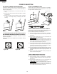
208/240 VOLT CONNECTI ON INSTRUCTIONS
The rangecan be set for208Vor 2 40V. The voltagesettingfor your
range is pre-set at 240V from the factory. Follow these steps to
change the voltage setting.
1
Locate the voltage switch on the lower back side of the
range.
2
Removethesc rewand rotatetheswitchplate180 asindicated
in the Figure 3.
3
Reinsert the switch plate and replace scr ew as indicated
in Figure 4. The voltage setti ng is indicated by the visible
marking.
POWER CORD CONNECTIONS
4-WIRE CONNEC TION INS TRUCTIONS-FIGURE 8
Beforewiringt herange,reviewthesuggestedpowersourcelocation.
Ifconnectingtoa4-wireelectricalsystemfora
new branch-
circuit or mobile home use a 4-wir e connection.
1
Follow the powe r supply kit manufacturer s In stallation
Instructions supplied with the strain relief clamp and install.
See Figu re 7.
2
Insert the end c onnect ors for line 1, line 2 and neutral and
tighten securely to the termin al block.
IMPORTANT
DO NOT LOOSEN the factory installed nut
connections which secure the range wiri ng to the terminal
block. Electrical failure or loss of electrical connection may
occur if these 3 nuts are loosened or removed.
3
You must disconnect the ground strap. Remove the factory
installed ground screw and plate to release the copper ground
strap from the fra me of the range. Cut and discard the copper
ground strap and plate. KEEP the ground screw.
4
Connectthegreengroundwireleadwiththeeyelettotheframe
of the range with the ground screw using the same hole in the
frame where the ground screw was originally installed. See
Figure 8.
5
Make sure all screws a re tightened securely and replace the
rear access cover. See Figure 6.
3- WIRE CONNECTION INSTRUCTIONS
For existing installations ONLY, refer to Figure 9.
1
Follow the powe r supply kit manufacturer s In stallation
Instructions supplied with the strain relief clamp and install.
See Figure 7.
2
Insert the end c onnect ors for line 1, line 2 and neutral and
tighten securely to the termin al block. See Figure 7.
IMPORTANT
DO NOT LOOSEN the factory installed nut
connections which secure the range wiri ng to the terminal
block. Electrical failure or loss of electrical connection may
occur if these 3 nuts are loosened or removed.
240V
180
screw
ACCESS T O TERMINAL BLOCK
Loo sen screw on rear ac cess cover and pull down as illustrated in
Figure6toaccessterminalblockwiringconnection.Toclose,return
to original location and secure screw.
Figure 6
Figure 3 Figure 4
208V
screw
3 & 4-WIRE ELECTRICAL WALL RECEPTACLE TYPES &
RECOMMENDED MOUNTIN G ORIENTATION ON WALL
Figure 5A illustrates 4-wire r eceptacle required for new and
rem odeled ins tallations.
Figure 5B illustrates 3-wir e receptacle that is allowed for existing
installations.
Figure 5A
4-wire wall receptacle (14-50R)
Figure 5B
3-wire wall receptacle (10-50R)
strain-relief clamp
Figure 7
POWER CONNECTION