SHARP SERVICE MANUAL Personal Computer MZ-80K r DC 6 PS Ernst Helms Te!. O~534 / i441 SIE:ndamm 3 ~u3 1 Lasbek r !FEATURES ! • The MZ-80K is a full·fledged persona l microcomputer equipped with 8-bit microprocessor (2·80 ) and it can meet a variety of applications li ke hobbies, educat ions, office wor ks, controls (of apparatus In every industrial fie ld), etc . • It is a compact desk·top type, Itself a simplified unit including CPU board, CAT display, cassette -tape recorder and ke),) r.
MZ 80K ~------Contents---------.., Page Specifications . . . . . . . . . . . . . Precautions on Handling LSI's and IC's 3 Trouble shooting guide 4 CPU board section. . 5 Power supply section 12 Display section 17 '" Cassette tape recorder section 21 Keyboard section . . . . . 24 Circuit diagram of MZ·80K 25 Replacement Parts List 43 .. Caution in Service * Maintain the safety and protecting ability of the apparatus after service.
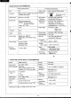
MZ-80K SPECIFICATIONS • General • CPU Z-80 Clock Function: Built in Memory Monitor ROM; 4K bytes RAM; 20K bytes (dynamic RAM) Memory extension; 48K bytes (max.) Editor function Cursor control; "up", "down", "right", "left", "home", "cleary home" Edit key, Delete key Display 10" CRT (black/white). 8 x 8 dot matrix, Characters; 1000 (40 characters x 25 lines) Power supply AC 220V ±10%, 50 Hz AC 240V ±10%, 50 Hz (for UK) Power consumption Approx.
MZ 80K • Display Section (DUTT0004PAZZ) I. General specifications 11. Electrical specifications Video output 40Vp-p standard (35Vp-p limit) Resolution Horizontal Size 10" Frequency 60Hz (vertical), 15.75kHz (horizontal) 15.75kHz (horizontal) Power source DC 12V, 1.1A±10% Non-linearity distortion Horizontal; ±8% (±14% max.) Vertical; ±8% (±12% max.) Quick start type (3 sec.) 240NB4; 10"90° deflection explosion proof type Heater; 12V. 75mA Geometrical distortion Pincushion dist.; 1% (2% max.
LSI's and IC's used in the MZ-80K are semiconductor integrated circuits whose basic element is MOS FET. The IC's, so poor in static electricity or leakage current from soldering tool, are liable to suffer breakdown. It is essential therefore to read the following instructions carefully and handle them properly. Cl) @ When inserting LSI's or IC.s, don't mistake their Ground your body before handling LSI's or IC's. Grounding must be made through a resistor of serveral Mohms for avoiding danger.
MZ-80K I • The machine comprises five main units, CPU board, display, cassette tape recorder, keyboard, and power supply circuits. For a quick solution to most operating difficulties, first consult the chart below to find which section of the machine is subjected to the trouble, and next to do the checkings according to more detailed instructions given in the succeeding pages. C___ S-,ta_rt_ _) No Check for the power supply circuit. No Check for the CRT display. No Check for the cassette recorder.
MZ-80K CPU BOARD SECTION The CPU board is composed of the following six blocks. When it gets in trouble, first locate which block is concerned with the trouble, and next try to check for its corresponding circuits; the wiring diagrams of every block will be shown separately. CPU in trouble Display block Yes Check for video RAM circuit. No Yes Check for IC5 (8255) and its peripheral parts. Yes Check for IC5 (8255) and its peripheral parts.
MZ-80K Display Block Character generator DO - ~ M " Shift register Video signal 7"- H-BLANK <~/~ 7"- V-BLANK ~ Sync signal Bus driver L-L-- D7 - I -'RD ~ -- Video RAM WR- CSD L-- ~ AO ~ -/ A9 1r V Address selector I I----- Oscillator Display controller circuit ~ Block Diagram of Parts around Video RAM , Problem 1. Sync. signal is not produced. 2. Video signal is not produced. , C.... P_ Vertical sync. signal: Check for IC15 and IC16. Horizontal sync.
MZ-80K • Cassette recorder/Keyboard Block D7 ~ DO PC5 PC4 PC3 -\ l' I I I READ I I Cassette SENSE I I I I L ~ I l L N ~ WRITE ~ ill Lt) -/ -------, [ PC1 I I MOTOR ______ -1I Motor controller Q) u ~ RD ------I ~ --c: Q; '" .c - WR ~ a. CS - .;: Q) D. Q) :c A1 AO - ) Decoder I I ~ I E E PAO ~o Cl PB7 l, H '" - ------, ~9 PA3 I ~ 0 .t RESET - I ) Keyboard ) I I .
MZ-80K • Audio/Clock Block 07 DO -\ --I ~ 31.25KHz -- '1 J Clock function INT Programmable counter (8253) RO 1/2 frequency division WR J> Au dio output 2MHz CS A1 AO -- I WR -- Oscillator circuit for Tempo Latch CS -- RO I DO Block Diagram of Parts around Audio/Clock Block Check Problem 1. No sound is produced. Is output signal present at pin Yes; IC12, IC3 No; IC18 2. Sound is distorted. Check for IC12 and IC18. 3. Tempo is abnormal. Check for IC13. 4.
MZ-80K • Memory Circuit Block AO ~ ____ A13 A15 ~ \ A12 Chip select A4 circuit \ A2 Data selector WR Driver RAM block D7 ROM DO AO~A11 Block Diagram of Parts around Memory Circuit Problem 1. Reproduced pictur shows "panic". Ch&ek Point Check for the following: ROM, IC46, CG, IC43 Address bus line; AO to A15 (IC44, IC45) Data bus line; DO to D7 (IC36, IC37, IC50) Control line; IC35 RAM (by using RAM checker*), IC52, IC53, IC56 2.
11' * How to Use RAM Checker Remove monitor ROM from the socket ("M-ROM" marked on the PWB) and insert RAM checker into the socket and turn on the power switch (the picture gets "panic" for about 1 second): then the following RAM TEST-1 and RAM TEST-2 will be automatically carried out from the address $1000 to the maximum address and the tested results will be displayed: the maximum address refers to $5FFF in the case of the standard set.
MZ-80K ~ • Write-in data $00 Read-out data $01 07 06 05 04 03 02 01 DO 0 0 0 0 0 0 0 0 0 0 0 0 0 0 IT] 11 I I I 3 20 12 I 4 13 I 5 DO 17 01 18 02 19 03 I I 9 10 RAM(l) $1000 RAM (II) $5000 $5000 RAM (Ill) $9000 RAM( I) RAM(ll) RAM,][i 1 2 04 I 21 05 I 22 14 I 6 I 06 I I 23 15 7 24 16 I I I I 07 8 ~ Error to occur $4FFF (with 16KRAM) ~$8FFF ~$5FFF (with 16KRAM) (with 4KRAM) ~$9FFF (RAM RAM $9000~$CFFF (RAM RAM $6000 ~$6FFF (RAM RAM ~ _ (1
I N 0 A CINPUT 0 ... E ... 0 L--- l- f - ...ro c .....en Q) ~ L-..- I Series 1 Regulator 1 Transistor Chopping Circuit Transistor Chopping Circuit Block Diagram of Power Supply Section Rectifying and Smoothing Circuit Rectifying and Smoothing Circuit Circuit I Control l Control Circuit +12V -5V G -u G +5V -v -v -v -u G '-J IZ 0 -t - ,~ en !< ." .
MZ-80K • Trouble Shooting Chart (DBOXD0004PAZZ) Problem 1: No voltage appears at any output terminal. Check for AC cord, AC socket, AC switch and C101. Is there AC 220V present across C101? Check for F 101 and T101 Problem 2: -5V is not developed. Check for T1 01. No Is there AC 9V present across the orange lead? Check for F201, 0201 and C201. Is there DC 10V present across C201? No Check for IC1, R201, VR201 and C202. Is there DC-5V present across C202? Ok Check for L201 and F202.
lVlZ 80K • Waveforms of Each Parts Waveform of pin (j) of IC2 and pin ell of IC3. Waveform of pin @ of IC2 0401 collector waveform I 23V 1-24~S..
MZ 80K • Trouble Shooting Chart (DBOXD0005PAZZ ----- for UK) Problem 1: No voltage appears at any output terminal. Check for AC cord, AC socket, AC switch and C101. Is there AC 240V present across C101? Ok Check for F101 andT101. Problem 2: -5V is not developed. Check for T101. Is there AC 10V present across the orange lead? No Check for F201, 0201 and C201. Is there DC 11 V present across C201 ? No Check for IC1, R201, VR201 and C202.
MZ 80K • Waveforms of Each Parts Waveform of pin Cl) of IC2 and pin CV of IC3.
I -...J Contract t B,;ghtn", Video amp. 02001 Power supply +12V Horiz. sync. signal To horizontal circuit To FBT circuit To CRT heater To vert. circuit To audio circuit To video amp. To sync. separator AFC 02002, 02003 V-HOLD V-LlN H-HOLD Horiz. drive 02004 Volume Horiz. output 02005 Audio signal amp. IC2002 Video signal Block Diagram of Display Section ~ Horiz. osc. 02003 V-SIZE tr t Vert. sync. Vertical ,-----------" signal ,---------------, horizontal sync. signal Vert.osc. Sync.
i\1Z SOK • Trouble Shooting Chart Problem 1: No picture appears. No picture Y 1 N~ Check for CPU board. 1- .. Check for +12V power supply. Only raster appears. N°rl Check for CPU board. Check for video input signal. I----, ~ Ok Check for VR· R2002, 02001 and vide0-40V power supply. Check for video OkL. circuit. Neither L. raster nor picture appears. No r1 4 IJ Check for CRT heater. Check for CRT plug. -1 CRT in trouble. Check for middle/ Ok.....
MZ 80K • Waveforms of Display Section Video output signal Video input signal Video output signal ® CV (,J) 1111111 +1111111 ·+11][111 ,+pl l l Il~ 1111111 --- 1111111111 5ms 5ms 5ms Sync. input signal Sync. signal amp. output Vertical sync. signal ® ell (4) r-- Tl Tr-1 12Vpp L- L 20l's Vertical oscillator Circuit sfVl ® of 2ms @ ~l TI 10r I t ,-- l 1.5Vpp 5ms nL - 5ms AFC waveform FBT waveform \1jJ 20l's Vertical linearity circuit waveform "ll 5ms l ..i...:.
MZ 80K Horizontal oscillator waveform Horizontal oscillator emitter waveform Horizontal oscillator output waveform 1- I 7Vpp --t-- ! 8Vpp 5V 5V \U 'U OV OV 20lls Horizontal drive collector waveform Horizontal output pulse Horizontal output base waveform n 3V L AFC pulse Middle voltage FBT pulse Video power supply pulse T 160V OV 150V 1 I " 20lls Audio input signal Audio amplifier output waveform Audio amplifier output waveform 5V li! OV 0 Audio output waveform The figures
I I\J ..... JlJlfL JLJlJL READ WRITE Power supply for motor : 0 '"' I 0 'fl ~ • Amplifier circu it 03001,03002 Differentiation circuit R3005 C3002,R3005 .. Block Diagram of Cassette Tape Recorder I o-o0~ 0 Play button Erase head - +5 v -v Amp. circuit limiter circuit IC3001 ( 1/2) Amp. circuit 03003 Record/playback head TAPE -o~z m en :a cm :a 8 m :a m i!.
MZ 80K • Trouble Shooting Chart Problem 1: Even if the play button is pushed, neither motor rotales nor tape moves. ~ Electronic governor motor defective. J Check for motor voltage: see if there is +12V t----between M+ and M-. N~ No r-1 Is voltage at the switch f-(inter·locked with the play button) in high level? Switch defective J Ok ;--< Check for vOlt~ at cheak point 4 (SENSE): it must be I-OV with switch on and +5V with switch off.
MZ-80K • Azimuth Adjustment and Head Cleaning * Azimuth adjustment of record/playback head 1. Connect a synchroscope to the collector of 03003. 2. Load a test tape (TEAC, 3kHz-signal recorded) and play it back. 3. Rotate the azimuth adjusting screw so that the waveform on a synchroscope will be the maximum. Head azimuth adjusting screw Record/playback head , / Head cleaning Clean the heads, capstan and pinch roller often, to remove dust and tape residue.
MZ-80K • Waveforms of Cassette Tape Recorder 1st stage amp. output waveform CD _Iv ~-~- -- - Operational amp. input waveform Operational amp. input waveform ® CID L pp 6mV~ pp 1.8V T DV -- Operational amp. input waveform Operational amp. output waveform @ @ n T{ ® -r- f1 Output waveform e- T I 1.5Vpp i 4Vpp Lv " u V v ~ , v v 5Vpp ---'- L- I Record input waveform CD v 2 r ,1MB l ® ® .- r- .- ~PJ .- - T e- i 4.8Vpp I _L I Record amp.
MZ-80K CIRCUITDlAG • Symbols of CPU Section r- (liS-I :;: 0 :;: £::! + ~* BSJ ~~ 6S:) ~~ 09J ~~ 19J ~~ <:9J ~~ £9J ~~ v9J ~~ L9J ~~ <:BJ ~~ £BJ ~~ 00 B9J ~~ 10 t>BJ ~~ 69J ~~ ZO SBJ ~~ OLJ ~~ 9BJ ~~ !LO ILJ ~~ tp() L8J ~~ UJ ~~ BBJ ~a ~~ I{) Z
I I en I\J ISlea5 +5V 7414 'C4 i i i i _ 71 ft_ rnw iiiEQ RFSH......--1@i .HT '. +5V II· I 27 RD RESET 6 vec HALT iiii ft ~= 2. ~ I: +5V M MPU AND SYSTEM BUS A" A.. AM A.. Do D, D. ::::I 0' ~ f C. I» .~ C ~ D. ~ 0 3 Z80 CPU D4 60 I» Di' ce . -... ;:;: C (') Ri) D7 Do .
I I ..... I\J RAM MEMORY +12V +sv -sv ADo AD A02 A05 AD4 AD I ~ • I • RAS RAM24 DOUT RAMI6 DOUT I WE DIN I AOAI AlA.A4 AS!:§' CAS AS DIN WE RAMS Aa AI A2 A.
I I r-J 00 RAS. 11 9 iif- IC52 LS ~ ~a RAS, 1C52 ~ ~. RAS, >--------i le: 3 ~2 SI CSO Q .. 3 RFSH C LS74 ICSS 0 PR 4 cs. 3 r IOk •• RA 2 CK 11 iiJiEij 3 12 IC54 . 6 ICSI Y .*1 1 D~ 20 LS I -Hr LS 20 .---... 13 ~ LS 20 1C54 R46 I e 6 3 74 ... '7 ....!.. . +.V 110 9 I 11 2 12 3 13 4 • 14 15 6 16 • 7 CSI 1C54 a 6 RD Cfl CS.. CS7 Cii cn CSA Cili CiC D07 0D0 DOa - DOo DO. DO. DO, 2 00 D.
I I\) I co AI ADI AO A7 ADO A8 AD2 AD3 I I IC56 5157 A3 A2 A9 ADDRESS DECODER RAM ADDRESS MUX AND Alo ¥ I 12 SI LsOO All AS rI A8 IC57 150 CS2 0 A 0 ~ ffi ....\, 9 8 m E12I"- • 8 CS6 E6 • CAS cse:oCsEi CsE2 rrr B C LS42 IC30 I" I~ I. AA CSD CSC CSA CSB CS9 6 Ii 7 6 m Ell I. 16 .• U5 13 14 12 11 10 13 11 10 9 7 4 Ii CS4 E4 3 0 2 3 CS3 E3 2 4 CS2 E2 m CSO 1C47 154 G2 GI 19 18 MREO ~ :::I 0' rSl a. III W C .
I w o I '~7 IL4 2 Rl 220 "- U~ I~:K IC7 ~ IIL~ 10 -1P 1 I R4 MO J rK a I C19 IC22 00 LS IT ~ 0 • 10 9 ~ ---..!.CK 11 LSI07 IK le 7 ~. f!Y' 'MD. SYNC COUNTER I B 6 IC22 !5 4 IC26 86 T'L---' IC26 6 IG 131 12 2G 23 ~ ~ ~~:5 l~~ OD IC9 LS93 Qc A II~ J ~OS7 0 F--- '--! CK --= J 8 O'~A QA QI 9 ICI4 LS93 8 121l 31.2!5K Qc 8 Cl Kl ~~ IC25 I r- J Q !5 5 101 4 I 2 102 10> 104 2:04 J~Ol J~022~0'JJ (d) (e) (f) +.
...wII • A. 3 4 5 6 7 • 'I WR CSll OIR 9 G 02 LS 13 48 '1 A.~ lA S 2A SA AZ~ A'~ 4A As~ G "J. LSIS7 L- IY~ 4Y " 5Y 9 A. 6 r-- 5"" 'Y IC40 1C21 • (.)~ 28 58 I (a)>-----l 18 (.)~ (C)~ 1C23 12'~ " III 18 17 16 15 I. 13 I• eo" 1tT 9As CHAR ACTER GENERATOR AND VIDEO RAM RC 00 D. Do D. 04 00 O. D. LS245 IC43 Az 7 As 4 I.o ft 3 Aa O. I As 18 As 15 et 8J. 4Y rL- IL CS 51"" AI iI! 10 "d.
Q3> VIDEO GENERATOR I<,;LU ,'-'" (g) q 11 +5V (2M) H-Blonk H-Synch GND +12V SND +12V GND GND SOUND • ~ o· ~ n Cl) (I) Q. III ... CJ 0 "'0 C (') 2- 3 '::::i CC ...III ;::;: 0 ii· n c: ...
1 tu tu 1 .~ 7 GND 26 IVcc B25~ IC5 35 RESET A'3 AI AO RESET 8 9 Aa CSEO~CS Wii~WR Ro~Ro 04 05 De 07 ~ ~ ~ RA' +'V IOK X8 I 1(i)(2)@(4)®OO(rl@®@6' P80~8 Ps,'S PB2~ PB." PS.!!! 2 , o ' • 4 4 • • 5 6 '5 A LSI4~ 7 9 6 7 14 B Tt.;: §j PB6~ PB7~ PAD PA, 8 '0 I3 C '2 D 9 " J PA2 IC6 V-GATE - " V-Blank PA. • PCO~ PCI~ PCZ 16 PC! 17 PC4 13 u.. PA7fllPC7 10 peG PCS 12 ICl ,.!.lOUT ~~~ 17 • J 111 I I 1 __ .1'1'4 IC4 LSI4 3 ~ C14 I.
I I oil> eN ,~ 01 00 7 8 01 Do CSET Ao 19 20 21 AI 23 WR Ri) Ao AI CS WR RO 02 6 02 04 22 03 5 03 GATEO ClKO OUT 11 9 10 14 15 13 16 18 TIMER AND SOUND IC18 8253 GATEI ClKI OUT! GATE2 ~ 04 O~ 3 0UT2 ClK2 07 2 D6 4 06 07 17 ,~ 2M 10K 31.25K R13 +5V ~ 06 IC3 12 II n 6 ~V 13' CK lS74 IIC12 INT 1=>;> t;, CRO 555 THRI 6 , Cs ....... • Rl0 ,O+~V I ~~~2 C4 IOOPF , Cl coo 3 10UT JCt Q I ":J4:t 6 s :::>r..
I I U1 w ... - [> (MARK) G 10RQ G G HALT RESET G G G G G 5 6 7 8 9 10 11 12 13 14 15 16 17 18 19 20 21 22 23 24 All AIO A9 A8 A7 A6 A5 A4 A3 A2 AI AO G 07 D6 05 D4 03 02 01 G G G G G MT G WR G RO INT BUS CONNECTOR DETAIL 25 MREQ 4 AI2 00 G 2 3 AI4 AI3 G I AI5 B I A - -5V GND +5V +12V " C38 -25V =: =~ ~ =+100 J.l I~~ C37 2SV IOOJ:J: 25V C36 o I- k) -5V GND 10 +5V P+12V • ~ er ~ do en CD Cl) 0 OJ C n -a 0 .... S 3 -...
+r:w C301 -liI- II.L-.J 11. ~ -liI~ 12 - 0 O C302 . "~ g. E ~ c( . ~~ ~~- ~ E c4t + III ~"I V..-.v T~ 'H- ~~_ .l8 --u- . 0401 + o -5 ~ ... IL 0 E 0 +12 &T1,6A I~I F401 L402 ~ o +5 '0 + 01 10 If)?~ o .L~ -'VVIt--It504 & T1.tiA I~J F501 C506 -H- 0502 0501 Hf~~1 --=- *8 C502 "'* - fi -J'VVV""-a: J\NIr ~1£~U ~t 1tJ T6 ...... L503 ~ ~~t@ C403 """" J\NIr R405 C40{'"R~' ~~i w-~ §~~ j .
I I w ..... L ±IO% AC 220V 650101 &SWIOI I I I I 1 1 I 1 rf"\Jl I 6T!500m I F201 POWER SUPPLY CIRCUIT - 11 ~ 6TIOI I----~ ___ __, Al 2500}l/55V C30I ... C3041 \:501 IOll/S5V Jl78MGU~ VRZOI 12K .20' ~ ZOOIO + C202 470/lOV ~-!5V L201 6T31!5mA F202 ZOOO9 Zoo07 F401 MZ-80K L402 L401 • er:::J ~ ~ -< 'C 'C (I) C ~ ~ "8 So 3 I» i'...
I I ~ .a L AC240V ±IO% &50101 &5W101 I I I I I I i &TIOI I rrv:>, (FOR UK) .:a.. POWER SUPPLY CIRCUIT III --------, C50I ... C!041 25OOp155V ~501 IO~/"V , COOl 470/IOV A R501 4.7K .... F202 ~-5V Z0007 L401 F401 + 12V MZ-80K L402 ZOOO9 ~ o -:; .c: -" f ~ er ::J -< 'tJ 'tJ en c ..f ~ o 3 DJ a::a Ai" a::a C 5" ::;" .....
I I w co -~ + u +~ R2051 + A/' ",. 2 I 7 8 R2047 1 R2025 1""""" + R2046 VOLUM E ~ .. R~~';6 K H .. C -It- R2002 'I." ..... 02009 + CONTRAST ~ EO G .. .. -It- "!;! ,,2 U fjT R2042 + C2051 -If- 2 FOCUS R2044 Raoeo .. • u +T ~ ~ 0 N ... V-HOLD R2017 ~ R2037 ':;':' L2001 .. H-HOLO ~ T NT U R2033 ~ R2043 --JWv-- ~ Si! 0 2 ~ • 0 t., NO.~ C2025 + C 2 ~.. ~ =" +. ~ TOfj :f f t!;!~ 02003~ ;J.
1 "'" 0 1 _. +12V GNO Video " Sync Sound 330 R2026 15. 02013 12. 0015 02004 47 ~ _ B- r OO33 1c2007- +___ 7 2.7K 10. R2019 1 ,. V-SIZE - C2014 22u/16V 02007 1500< + C2003 ,OuIl6DY I. R2024 llW I.OK RC-ElOO29TA R2023 330 602051 12 L2002 ,-----+-"'-1 Rei LZOO5TTA (:~OO4TAI V-LIN R2025 R2021 1.511/2WI C20I~~12 22~/16V \!!I SeOK R2045 20K(BJ(M'r'O~2TA) R2022 n > Ip/35VITNI ~R2014 ® _ • R201. 27. lUJ( IK(1I2W) R200S 02006 2.2M -..:1 ~.~~:sv +·.tl'"C2..
MZ-80K • Symbols of Cassette Section C300t e ~3001 ~R3004 ~~ ----'Wtr- R300 3 ~ C3002 .x 0 an o -1'-. R3006 ort) 0: ~ rr> 0 ::t R3007 J\ ~ R300~, -r Q3003 a.. LO N o lJ.. 10 -11- ~ ~u R3010 C3006 -1 r- R3011 ~ R30 12 -.J...Nr- J...
I I\J 1 .-. 1000P .L. C3OO!II .1 _ SW 3001 R3007 47K 'Q3OO3 2SC1681 R3012 22K C3007 R3011 1000P 47K ~ FO 259P ~T1f~~f,~@ r-----------------i R300I 470 CASSETTE TAPE RECORDER SECTION K TRC - 0004 PAZZ C3004 12:! 0 + MZ-80K R30ZI 2MG IOK ~ R3002 ~ :s !er I ~ 2- Dl 3 ea C 5° ea So ~o :e• ...
REPLACEMENT PARTS LIST To MODEL MZ-80K REF. NO. PART NO.
, IV1Z 80K PARTS LIST REF. NO. R20 R21 R23 R24 R25 R341 R40 R37 R42 R43 VR RA1] RA2J r PART NO. DESCRIPTION CODE REF. NO. VRD-ST2EF271J VRD-ST2EF822J VRD-ST2EF152J VRD-ST2EF473J VRD-ST2EF123J 270 ohm 8.2K ohm 1.5K ohm 47K ohm 12K ohm AA AA AA AA AA VRD-ST2EF101J 100 ohm AA VRD-ST2EF153J VRD-ST2EF332J VRD-ST2EF331J RVR-MOO19PAZZ 15K ohm 3.
~ • MZ-80K PARTS LIST REF. NO. DESCRIPTION PART NO.
MZ-80K PARTS LIST REF. NO. PART NO. L2001 L2002 RCILB0021TAZZ RC I LZ0057T AZZ DESCRIPTION H-Hold Variable Coil H-Lin Coil CODE REF. NO. AG AG MISCELLANEOUS ...• (lPWIF0261PAZ.Z.· PRDAF0147TAZZ PRDAF0107TAZZ OSOCV0701SEZZ OPLGN0404CEZZ OSOCNOO77PAZZ OCNW-0009PAZZ 2 GCABC8004PASC GWAKPOOOl PASC GCOVZOO05PAZZ LANG BOO02PAZZ LAN G B0003P AZZ DDAI-0004PAZZ PSHEFOO07PAZZ LANGOOO05PAZZ LANGSOO03PAZZ LANGSOO13CEZZ 3 4 5 6 7 8 9 10 11 12 /J:.
MZ-80K PARTS LIST REF. NO. PART NO. 19 20 21 GCABA8018PASA GCABB8018PASA GCABB8019PASA PROAR0010PAZZ OSOCN0016PAZZ 22 LBSHCOO03PAZZ REF. NO. OESCRIPTION Cabinet Cabinet Cabinet (for UK) Radiator Lead Wire with 4-pin Socket Rubber Bush PART NO. DESCRIPTION COllEj CAPACITORS AF AB C3001 C3002 C3004 C3006 C3008 C3003 c30051 C3007 J C3009 VCEAAU 1AW476Y 47MFO, 10V, Aluminum AB VCOYKU1HM104K 0.
MZ 80K • PARTS LIST REF. NO. PART NO. DESCRIPTION CODE REF. NO. MISCELLANEOUS 43 44 45 46 47 48 49 50 51 52 QPWBF0172PAZZ QSOCN0080PAZZ DCABA8042PASA GCABB8017PASA DANG-0006PAZZ LH LDF0011 PAZZ GLEGROO01PAZZ MHNG-0001 PAFC MARMM0019PAFC QACCK0050AFZZ QACCB0001 PAZZ LBNDC0001 PAZZ 53 Printed Wiring Board for LED Lead Wire with 3-Pin Socket Cabinet Cabinet Arm Fixing Angle with Screw CPU Board Holder LEG Hinge Support Arm A.C. Cord A.C.
? I ~ , @ 5 1 I , r ./ Qi~ ~"...... @ Y '120' 1 v-1 ( H, V) I . L---1 @--i • • I B 1 9) ..,/ ' c h r;;:;-. '® 27 ~ '--0' -B 66 65 106 I @@ 71 72 EJECT LEVER ASS'V (H, VI cJ f-.. O/ • r-e 17 A @'- I @-- "' 100 ID. 115 99 98 B2 58 60 6' 62 64 65 69 70 72 73 7' BO 53 54 3' 40 36 37 3B 22 24 25 27 2B 29 32 33 35 21 19 15 17 "" 11 ,.• 3 4 5 B 2 NO . REF .
MZ 80K ® 1- "", . -. . L.·;'~'.. " - __ ® . Fig.
MZ-80K o o Fig.
MZ-80K j j j j j j j j j j j j j j j j j j .~ r . j j j ...it j j j j j Fig.
I ®--g 1-(----+-~--(@) @~ @-----r==J ?-{--~y@ 00000000 0000000 0000000 000000 000000 Fig. Key Board Section and Others -56- E810905 HO.