
Service manual


– 7 –
CD-BA120/125
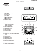
1 Top Cabinet 1. Screw ..................... (A1) x4 7-1
2 Side Panel 1. Screw ..................... (B1) x6 7-1
(Left/right)
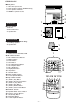
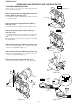
3 CD Player Unit/ 1. Turn on the power supply, 7-2
CD Tray Cover
open the disc tray, take out the
CD cover, and close.
(Note 1)
2. Screw ..................... (C1) x1
3. Hook ....................... (C2) x3
4. Hook ....................... (C3) x2
5. Socket .................... (C4) x2
4 Main/Headphones 1. Screw ..................... (D1) x11 7-2,8-2
PWB/Rear Panel 2. Socket .................... (D2) x4 8-2
3. Flat Cable............... (D3) x1
5 Front Panel 1. Screw ..................... (E1) x3 8-2
6 Display PWB 1. Screw .....................
(F1) x9
8-3
2. Flat Cable............... (F2) x1
7 Tape Mechanism 1. Open the cassette holder. 8-3
2. Screw...................... (G1) x6
9 Turntable 1. Hook ....................... (H1) x2 8-4
2. Cover ..................... (H2) x1
10 Disc Tray 1.
Turn fully the lock lever in the
7-3
arrow direction.
2.
While holding the lock lever,rotate
8-1
the cam gear until the cam gear
rib engages with the clamp lever.
3.
Push the slide holder backward to
8-5
engage the claw with the groove
and remove it in the direction
of the arrow. ..............
(J1) x6
11 CD Servo PWB 1. Screw ..................... (K1) x1 8-6
(Note 2) 2. Hook ....................... (K2) x2
3. Socket .................... (K3) x4
12 CD Mechanism 1. Hook ....................... (L1) x2 9-1
2. Hook ....................... (L2) x3
13
Loading Motor PWB
1. Hook ....................... (M1) x5 9-1
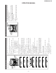
DISASSEMBLY
Caution on Disassembly
Follow the below-mentioned notes when disassembling
the unit and reassembling it, to keep it safe and ensure
excellent performance:
1. Take cassette tape and compact disc out of the unit.
2. Be sure to remove the power supply plug from the wall
outlet before starting to disassemble the unit.
3. Take off nylon bands or wire holders where they need be
removed when disassembling the unit. After servicing
the unit, be sure to rearrange the leads where they were
before disassembling.
4. Take suffcient care on static electricity of integrated
circuits and other circuits when servicing.
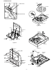
Figure 7-2
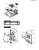
Figure 7-3
CD-BA120/125
STEP REMOVAL
PROCEDURE
FIGURE
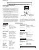
Note 1:
How to open the changer manually. (Fig. 7-3)
1. In this state, turn fully the lock lever in the arrow direction
through the hole on the loading chassis bottom.
2.
While holding the lock lever, rotate the cam gear anticlockwise
until the cam gear rib engages with the clamp lever.
(Fig. 8-1)
3. After that, push forward the CD slide holder.
Note 2:
1. After removing the connector for the optical pickup from the
connector, wrap the conductive aluminium foil around the
front end of the connector so as to protect the optical pickup
from electrostatic damage.
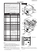
Figure 7-1
CD-BA120/125
Note 3:
1. Be careful not to break the claw of the CD mechanism.
2. When fining back the cam gear assembly, let it lock by front
movement.
(B1)x4
ø3x12mm
(B1)x1
ø3x10mm
Rear
Panel
(B1)x1
ø3x10mm
Side Panel
(Right)
Side Panel
(Left)
(A1)x2
ø3x12mm
(A1)x2
ø3x12mm
Top Cabinet
(C3)x1
(C1)x1
ø3x12mm
(D1)x3
ø3x12mm
CD Player
Unit
CD Tray Cover
Rear
Panel
Pull
(C3) x1
(C4)x2
(C2) x3
1
1
2
Main PWB
CD Servo
PWB
LOCK LEVER