CD-BA1200H SERVICE MANUAL No. S4029CDBA1200 CD-BA1200H CD-BA1200H Mini Component System consisting of CD-BA1200H (main unit) and CP-BA1200H (speaker system). • In the interests of user-safety the set should be restored to its original condition and only parts identical to those specified be used. • Note for users in U.K. Recording and playback of any material may require consent which SHARP is unable to give.
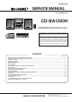
CD-BA1200H (Except for U.K.) SAFETY PRECAUTION FOR SERVICE MANUAL Precaution to be taken when replacing and servicing the Laser Pickup. The AEL (Accessible Emission Level) of Laser Power Output for this model is specified to be lower than Class I Requirements. However, the following precautions must be observed during servicing to protect your eyes against exposure to the Laser beam.
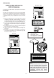
CD-BA1200H IMPORTANT SERVICE NOTES (FOR U.K. ONLY) WITHSTANDING VOLTAGE TESTER Before returning the unit to the customer after completion of a repair or adjustment it is necessary for the following withstand voltage test to be applied to ensure the unit is safe for the customer to use. Setting of Withstanding Voltage Tester and set.
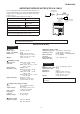
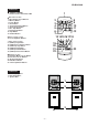
CD-BA1200H NAMES OF PARTS CD-BA1200H 1 2 Front panel 3 4 5 6 1. (CD) Disc Tray 2. (CD) Disc Skip Button 3. (CD) Track Down/Review Button (TUNER) Preset Down Button (TAPE 2) Rewind Button 4. (CD) Track Up/Cue Button (TUNER) Preset Up Button (TAPE 2) Fast Forward Button 5. Timer Set Indicator 6. On/Stand-by Button 7. Timer/Sleep Button 8. Clock Button 9. Function Selector Buttons 10. Equalizer Mode Selector/Extra Bass/Demo Mode Button 11. Volume Up/Down Buttons 12. (CD) Open/Close Button 13.
CD-BA1200H CD-BA1200H Remote control 1 1. Remote Control Transmitter LED CD control section 2. Disc Number Select Buttons 3. Memory Button 4. Pause Button 5. Clear Button 6. Track Down/Review Button 7. Track Up/Cue Button 8. Disc Skip Button 9. Play/Repeat Button 10. Stop Button 11. Random Button 2 3 4 5 6 7 8 9 10 11 12 13 14 15 1617 18 Tuner control section 12. Preset Up/Down Buttons Tape control section 13. (TAPE 1) Play Button 14. (TAPE 2) Record Pause Button 15. (TAPE 1/2) Stop Button 16.
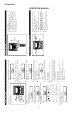
–6– 5 AM 12:00 ) button to select the (AM 12:00 - PM 11:59) The 12-hour display will appear. (AM 0:00 - PM 11:59) The 12-hour display will appear. (0:00 - 23:59) The 24-hour display will appear. AM 0:00 or Press the MEMORY/SET button. Note that this can only be set when the unit is first installed or it has been reset. "AM 12:00" "AM 0:00" "0:00" 0:00 Press the TUNING/TIME ( time display mode. Within 5 seconds, press the MEMORY/SET button. 3 4 Press the CLOCK button.
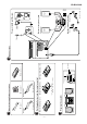
FM aerial × 1 3 AC power lead × 1 –7– 10 cm (4") 10 cm (4") Placing the system Remote control × 1 10 cm (4") 10 cm (4") 3 Replace the battery cover. 2 "AA" size batteries (UM/SUM-3, R6, HP-7 or similar) 2 Insert the batteries. Putting batteries into the remote control 1 Remove the battery cover. 2 AC power lead × 1 [Except for U.K.] AM loop aerial × 1 Check the supplied accessories [For U.K.] 1 4 Connections FM aerial 2 1 [For U.K.] AC 230 V, 50 Hz [Except for U.K.
7 6 5 –8– 4 3 PUSH EJECT 4 1 2 TAPE 1 3 TAPE 2 2 3 PUSH EJECT 5 6 Listening to a tape 2 1 Listening to the radio 7 3,6 5 8 cm (3") 12 cm (5") 8 5 1 2 4 Listening to a CD or ) button to tune in- 2) button to select the TAPE 1 5 Press the button to start playback. 6 Adjust the sound volume using the VOLUME buttons. or TAPE 2. 4 Press the TAPE (1 And then, close the cassette door completely until it is locked. compartment.
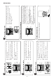
CD-BA1200H DISASSEMBLY CD-BA1200H Caution on Disassembly Follow the below-mentioned notes when disassembling the unit and reassembling it, to keep it safe and ensure excellent performance: 1. Take cassette tape and compact disc out of the unit. 2. Be sure to remove the power supply plug from the wall outlet before starting to disassemble the unit. 3. Take off nylon bands or wire holders where they need to be removed when disassembling the unit.
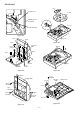
CD-BA1200H (J2) x1 Clamp Lever Turntable CD Player Unit (Top View) Disc Tray (J1) x2 Cam Gear Rib Figure 10-1 (E3)x1 CD Player Unit (E2)x2 (E2)x1 Figure 10-4 Headphones PWB (E1)x7 ø3x10mm (K1) x3 2 (E4)x1 (E2)x1 1 (E1)x1 ø3x10mm Main PWB (K1) x3 (F1)x3 ø3x8mm Figure 10-2 Figure 10-5 (G2)x1 Display PWB (L3) x2 (G1)x9 ø3x10mm (L1)x1 ø3x8mm CD Servo PWB (L2) x2 Tape Mechanism Open (H1)x5 ø3x10mm Cassette Holder (L3) x2 Figure 10-6 Figure 10-3 – 10 – Slide Chassis
CD-BA1200H Cam Gear (M2) x3 CD Mechanism Loading Motor PWB (M1) x1 (M1) x1 (N1) x5 Figure 11-1 CP-BA1200H STEP 1 PROCEDURE REMOVAL Speaker 1. Net .......................... (A1) x1 2. Duct Panel .............. (A2) x1 3. Screw ...................... (A3) x4 FIGURE 11-2 11-3 CP-BA1200H Speaker Box Speaker Box (A1)x1 Speaker (A2)x1 (A3)x4 ø3.5x13mm Driver should be pried away from Speaker Box.
CD-BA1200H REMOVING AND REINSTALLING THE MAIN PARTS TAPE MECHANISM SECTION TAPE 2 Perform steps 1 to 6 and 8 of the disassembly method to remove the tape mechanism. Record/Playback Head How to remove the record/playback and erase heads (TAPE 2) (See Fig. 12-1) 1. Carefully remove the record/playback head and erase head screw (A1) x 2 pcs. Erase Head How to remove the playback head (TAPE 1) (See Fig. 12-2) (A1)x2 Ø2 x 9mm 1. Carefully remove the playback head screw (B1) x 2 pcs.
CD-BA1200H CD MECHANISM SECTION Perform steps 1, 2, 3, 9 and 12 of the disassembly method to remove the CD mechanism. How to remove the loading motor (See Fig. 13-1) Loading Motor 1. Bend the hooks (A1) x 5 pcs., to remove the loading motor. (A1)x1 (A1)x2 (A1)x2 Slide Chassis Figure 13-1 How to remove the pickup (See Fig. 13-2) Stop Washer (B1) x2 (B3) x1 ø2.6 x6mm 1. Remove the screws (B1) x 2 pcs., to remove the shaft (B2). 2. Remove the stop washer (B3) x 1 pc., to remove the gear (B4). 3.
CD-BA1200H • FM Notes: 1: Description of the "FM IF Adjustment" is not carried on this Manual. It is because the IF coil in the FM front end section has been best adjusted in the factory so that its further adjustment is not needed at the field. When replacing the FM front end assembly, no adjustment is needed either.
CD-BA1200H NOTES ON SCHEMATIC DIAGRAM • The indicated voltage in each section is the one measured by Digital Multimeter between such a section and the chassis with no signal given. 1. In the tuner section, ( ) indicates AM < > indicates FM stereo 2. In the main section, a tape is being played back. 3. In the deck section, a tape is being played back. ( ) indicates the record state. 4. In the power section, a tape is being played back. 5. In the CD section, the CD is stopped.
CD-BA1200H WAVEFORMS OF CD CIRCUIT Stopped CH1=500mV DC 10:1 CH3=500mV DC 10:1 T Stopped CH1=500mV DC 10:1 500ms/div (500ms/div) NORM:20kS/s CH3=1V DC 10:1 1999/04/05 17:33:17 CH4=1V 500ms/div (500ms/div) DC 10:1 NORM:20kS/s PDO1 1 7 FDO IC2 24 1 IC2 1 3 4 8 2 IC2 23 T 3 1 CH1 v/DIV 500mV =Filter= Smoothing : ON BW : FULL =Offset= CH1 : 0.000V CH2 : 0.0V CH3 : 0.000V CH4 : 0.
CD-BA1200H SW2 SW3 SW1 OPEN/ CLAMP DISC NUMBER CLOSE M3 T/T UP/DOWN MOTOR M 6 7 8 9 10 4 5 6 1 2 3 4 5 6 1 2 3 4 5 6 CNP12 BI4 3 CNS4 CLAMP SW 5 2 CNP4 + - 1 GND CD RES 4 CLK CE 3 DI 2 DO 1 DRF 5 CDINT 4 WRQ +5V(+B4) 3 CNP11 2 TO DISPLAY SECTION DGND 1 L-CH R-CH AGND TO MAIN SECTION (TO IC601) CONT2 30 CONT3 32 31 RCHO LVSS RVSS 45 46 47 48 LCHO 76 CONT4 66 CL 75 CONT7 65 CE CONT6 Q2 74 64 67 DI 40 68 DO 19 13 69 INT IC2 LC7864
CD-BA1200H +B3 FM ANTENNA FE301 TA7358AP FM FRONT END 8 6 CF302 AM LOOP ANTANNA CF351 X351 456kHz 5 T351 CF352 4 3 7 Q301 Q AM IF FMOSC 2 CF301 1 4 5 1 2 8 9 IC303 AM IF GND FM+B FM DET LA1832S FM IF DET./FM MPX./AM IF AM MIX 17 13 VCO MO/ST L 14 R FM/AM OUT MPXIN 18 7 16 12 STEREO AMRFIN L341 BALUN FMAFC AMOSCIN 23 22 21 24 15 FM/AM AM TRACKING AM BAND COVERAGE TAPE MOTOR M SOLENOID T2 PLAY OSC Q706 +2B Q704 Q705 IC701 54PIN +2B R.
CD-BA1200H +B3 FL701 DISPLAY 1 2 10 3 13 15 16 19 20 22 26 11 14 17 18 21 27 30 31 32 33 Q701 +B6 59 58 57 56 55 54 53 52 51 50 49 48 47 46 45 44 43 42 41 40 39 38 37 SYS.STOP 36 35 +B6 AVDD 34 33 VDD 71 78 79 VLOAD IC701 IX0337AW SYSTEM MICROCOMPUTER 80 91 92 31 1 4 5 6 9 10 11 12 13 15 16 17 7 XL701 4.1943 MHz +B6 DO DI CL CE 100 VDD VDD RESET 99 KEY SW701-SW703 SW709-SW721 SW723-SW725 20 21 22 23 24 +B6 TO CD SECTION RESET SP.DET.
CD-BA1200H CD SERVO PWB-B A B F 7 6 7 6 7 6 5 5 5 5 R51 68K TIN1 4 4 4 4 R52 68K FIN1 3 3 3 3 R53 68K FIN2 2 2 2 2 R54 68K 1 1 1 C23 0.047 TIN2 R56 68K IC1 LA9235M SERVO AMP. R55 68K C24 2.2/50 C11 0.47/6.3 1 FIN1 CNP1 C 7 6 30 1 FIN2 REF 2 29 REF TIN1 C54 47/10 C C55 0.01 C7 10/16 VREF R47 3.
CD-BA1200H 1K 100P R75 1K DO C76 100P R76 1K DI C77 100P R77 1K CL C78 100P R78 1K L62 2.2µH CE CL DI DO INT WRQ DEF RES C80 0.1 COMMAND INTERFACE 64 SUBCODE DECODE CRC 63 PW 62 SBSY 59 DATA 58 DATACK A/D 51 50 17 18 49 48 + 19 47 LPF 1BIT DAC - 46 XIN EFLG CONT4 CONT5 RVDD 38 R-CH R82 2.2K LCHO C2F VDD DGND +5V C83 0.022 9 C31 100/10 CONSTANT VOLTAGE +B R16 10K L61 0.
CD-BA1200H A IC601 LC75341 AUDIO PROCESSOR 3 4 4 5 CD_GND +5v CE 2 L-CH 5 C607 +B B C613 0.0027 C617 1/50 SYSTEM MUTE Q601 2SC3331 D902 1SS133 C629 1/50 LSEL0 8 R607 2.2K R603 1.8K C633 0.001 C601 0.001 L3 10 L R608 2.2K 4 R2 TUN L1 12 Q602 2SC3331 SYSTEM MUTE GND (A_GND) R3 DECK L2 11 R617 3.3K 17 P26 1 - G TO POWER PWB C625 1/50 C602 0.001 R604 1.8K C614 0.0027 C618 1/50 17 R4 AUX R1 CD R616 3.9K C612 0.1(ML) 18 RSEL0 L4 9 C623 1/50 C610 0.
CD-BA1200H MAIN PWB-A1(1/3) +B 23 DD REF C605 0.022 C606 22/50 22 +B C604 100/25 24 C608 10/50 OUT 21 SS 20 TRE L0 10 GND (A_GND) 4 A_10V +B +B C614 0.0027 18 R3 R2 R1 5 CE C618 1/50 7 DI 6 17 R4 GND R616 3.9K C612 0.1(ML) 19 RIN (D_GND) C610 0.1(ML) CLK 9 C630 1/50 16 TUN_R 2 15 C624 1/50 14 C626 1/50 P29 12 - H TO TUNER PWB CLK TUN_L 3 DO R618 3.
CD-BA1200H A F F P15 P16 P13 P20 P14 P11 P10 P9 P8 P7 P6 5G P5 P4 6G 7G P3 P2 8G P1 P12 P19 P18 P17 1G 2G 3G 4G 9G F FL701 FL DISPLAY 1 2 3 4 5 6 7 8 9 10 11 12 13 14 15 16 17 18 19 20 21 22 23 24 25 26 27 28 29 30 31 32 2 C705 100/10 C708 1/50 R743 33 +B S-BUSY 77 P10 76 P11 T_T1/T2 75 P14 REC/PLAY 74 P20 RES OUT T-BIAS DRF WRQ 71 P15 70 DIST0 RESET 67 DIST3 66 65 64 D712 1SS133 CE 21 DISTOUT/SW OUT 33 KEY 2 CLK 22 53 T1 PLAY SW_A DO 24 52 CD CLAMP SW AVSS 25 55 FPA 51 T2 R
CD-BA1200H P4 6G 7G P3 P2 8G P1 P12 P19 P18 P17 1G 2G 3G 4G 9G F F 01 PLAY 16 17 18 19 20 21 22 23 24 25 26 27 28 29 30 31 32 33 Q701 KRC107M 2 1 BI702 R779 3.3 (1/2W) 3 CD INT WRQ(DSP) C707 1/50 R744 1K R745 100K C701 0.
CD-BA1200H IC901 LA4282 POWER AMP. A 10 POWER GND1 C915 470/25 R909 56K C913 0.1(ML) C914 470/25 R908 120 C919 10/50 C910 100/25 12 11 C936 100P C911 0.022 C912 0.1(ML) C903 470P C904 470P R910 270 (1/2W) C917 0.1(ML) R911 270 (1/2W) C916 0.1(ML) R913 4.7 R912 4.7 L OUT 9 8 OUT1 Vcc MUTE CIRCUIT 7 R OUT 6 5 POWER GND2 OUT2 NF2 IN2 4 C918 220P R905 120 PRE-GND IN1 3 2 THERMAL OVER VOL. PROTECTOR CH2 C908 0.082 (ML) R906 1K B 1 C907 100/25 C906 47/25 C905 0.
CD-BA1200H MAIN PWB-A1 (2/3) FM SIGNAL HEADPHONES PWB-A3 1 1 5 5 R916 330 FW902 L903 2.2mH C922 220P JK901 HEADPHONES R OUT L OUT C921 220P R917 330 SO901 SPEAKER TERMINAL L901 0.29µH + + R920 6.8 R918 6.8 C923 0.022 C925 0.022 C924 0.022 C926 0.022 C927 0.022 C929 0.022 C928 0.022 C930 0.022 SP_Lch SP_Rch SPEAKER – – SP_Lch_GND SP_Rch_GND R939 56 R919 6.8 C931 0.001 R921 6.8 R940 C932 56 0.001 C946 2200/35 L902 0.29µH C388 0.001 C950 0.
CD-BA1200H C302 0.001 A AM TRACKING fL T303 C332 0.022 AM ANT. D301 1SS133 +B +B C 21 22 AM RF IN 23 FM AFC 24 1 2 3 3 C350 0.022 T351 CF302 C352 10/16 1 D 0.022 C361 0.022 C363 R351 5.6K +B REG C334 27P(UJ) AM OSC. AM OSC IN L341 BALUN AM MIX OUT 2 AM OSC OUT 2 R358 3.9K FM IF IN 1 T306 R336 10K 1 VD301 SVC348S C335 560P C362 3.3/50 AM BAND COVERAGE fL R323 68K AM LOOP ANTENNA C342 0.022 D302 1SS133 CNP302 B C331 0.047 C330 15P (UJ) C323 0.
CD-BA1200H MAIN PWB-A1(3/3) FM SIGNAL STEREO FM DET VCC 6 7 8 9 R361 1.2K C372 1/50 R362 1.2K 13 MO/ST C374 0.018 R-CH OUT C371 1/50 R363 15K C358 12 1/50 10 11 R353 270 C357 R355 2.2/50 3.3K C398 100/10 C356 0.001 R388 3.9K C355 22P AM IF C354 0.022 C353 0.022 2 C399 0.022 CF352 CF351 3 C370 1/50 1 C350 0.022 R364 15K PHASE (FM/AM) SD 5 T351 R393 1K L352 100µH B +B +B ZD351 DZ5.1BSB Q360 KTA1266GR R377 47K 10 11 C391 47/16 R376 1K R360 4.
CD-BA1200H MAIN PWB-A1 A C912 C905 C910 3 2 1 C951 D916 D917 C958 5 R929 R930 LUG1 R928 ZD903 C956 R134 C146 C122 R122 C120 R145 R601 3 2 1 E C B Q601 Q113 C607 C601 1 2 3 4 5 R607 CNP11 P34 4 - A TO CD SERVO PWB 2 3 4 Figure 30 WIRING SIDE OF P.W.
CD-BA1200H SO902 AC INPUT AC 230V, 50Hz LG901 4 1 6 When Servicing, pay attention as the area enclosed by this line ( ) is directly connected with AC main voltage.
CD-BA1200H A DISPLAY PWB-A2 R745 B Q701 3 2 1 SW711 EQUALIZER/ X-BASS/DEMO C719 C718 FL701 C702 RD25 RD10 C 33 32 31 30 29 28 27 26 25 24 23 22 21 20 19 18 17 16 15 RX701 3 2 1 81 RD11 85 R701 C701 R703 95 5 10 I 15 XL701 C703 RD09 R704 R707 R706 R705 R709 R711 R712 R713 R710 R773 R724 R779 R768 Q706 B C E R766 B C E R708 R702 90 100 1 SW710 OPEN/CLOSE RD07 R718 RD06 R716 R715 SW719 FAST FORWARD RD26 RD22 SW713 VOLUME DOWN RD17 RD08 RD12 E R767 Q705 B C E Q7
CD-BA1200H P34 5 - A TO CD SERVO PWB CNP12 RD WH GY WH GY WH GY WH GY WH CNS702 1 2 3 4 5 6 7 8 9 10 1 10 BI702 2 1 LED722 FL701 SW701 ON/ STAND-BY C715 C711 RD01 R763 D704 D705 D711 SW725 TUNER (BAND) RD13 SW717 MEMORY/SET SW715 TAPE RD14 COLOR TABLE D706 CNS701 4 6 8 10 12 14 16 18 20 3 5 7 9 11 13 15 17 19 21 RD24 D703 D702 RD16 RD15 R769 L701 R775 R719 R777 R725 SW718 REWIND R776 R722 R721 R720 R755 R726 R717 R716 RD R715 9 R727 R728 R729 DISC SKIP RD05 SW721
CD-BA1200H R71 R78 R73 R74 R75 R76 R77 R72 R19 C71 C78 C73 C74 C75 C76 C77 C72 L61 R12 C23 R67 R68 C80 Q1 C21 R13 C82 40 41 CNP3 6 5 4 3 2 1 E 1 6 5 4 3 2 1 C38 10 XL1 9 C56 CNP4 C39 R81 C43 R83 R46 R17 R16 R20 45 C34 35 R95 R94 R48 22 C50 50 C30 25 20 21 65 64 60 55 30 C31 Q2 70 IC2 R45 IC3 1 2 3 30 R22 35 10 15 D21 D22 24 25 R21 R40 40 5 10 20 3 12 11 75 15 R38 C47 42 1 5 R82 C40 R84 R3 C28 R44 R35 R39 C46 C42 R52 R53 R51 R54 R43 2 C49
CD-BA1200H P32 4 - H TO DISPLAY PWB CNP703 TAPE MECHANISM ASSEMBLY FC702 1 TAPE MECHANISM PWB-D 13 1 3 5 7 9 11 13 2 4 6 8 10 12 4 1 8 7 TAPE MOTOR B A + - SOLENOIDE SOLENOIDE TAPE 2 BL GR 3 2 1 BL YL WH BK RD WH BK WH BK PK PT801 MAIN POWER TRANSFORMER RD YL WH GR BK BR YL YL RD BL BK 1 2 3 4 5 6 GR 0 RECORD/PLAYBACK HEAD PK P30 2 - C TO MAIN PWB CNP901 WH BK 3 2 1 ERASE HEAD WH TAPE 1 PLAYBACK HEAD 1 2 34 5 67 OR CNS101 P30 2 - G TO MAIN PWB BL 2 1 CNS102 P30 4 - H
CD-BA1200H VOLTAGE IC1 PIN NO. 1 2 3 4 5 6 7 8 9 10 11 12 13 14 15 16 17 18 19 20 21 22 23 24 25 26 27 28 29 30 VOLTAGE 1.6V 1.6V 1.6V 1.6V 1.6V 1.6V 0V 2.6V 0V 0V 0V 3.3V 1.6V 1.6V 1.6V 0V 0V 1.6V 1.6V 1.6V 1.6V 1.6V 0V 1.6V 0V 0V 0V 1.6V 1.6V 3.3V IC3 PIN NO. 1 2 3 4 5 6 7 8 9 10 11 12 13 14 15 16 17 18 19 20 21 22 23 24 25 26 27 28 29 30 31 32 33 34 35 36 37 38 39 40 41 42 VOLTAGE 1.6V 1.6V 1.8V 2.1V 2.1V 2.1V 2.1V 0V 0V 0V 0V 0V 0V 0V 2.1V 2.1V 1.6V 4.9V 3.5V 1.6V 0V 0V 4.9V 4.9V 1.6V 2.1V 2.1V 1.
CD-BA1200H TROUBLE SHOOTING When the CD does not function When the CD section does not operate when the objective lens of the optical pickup is dirty, this section may not operate. Clean the objective lens, and check the playback operation. When this section does not operate even after the above step is taken, check the following items. Remove the cabinet and follow the trouble shooting instructions.
CD-BA1200H (1) Focus-HF system check Stopped CH1=500mV DC 10:1 Although a CD is inserted and the cover is closed, "NO DISC" is displayed. CH3=500mV DC 10:1 T 500ms/div (500ms/div) NORM:20kS/s FDO 1 Press the OPEN/CLOSE switch (SW1) without inserting a disc, and try starting the playback operation. TDO 3 CH1 v/DIV 500mV =Filter= Smoothing : ON BW : FULL =Offset= CH1 : 0.000V CH2 : 0.0V CH3 : 0.000V CH4 : 0.00V =Record Length= Main : 100K Zoom : 2K =Trigger= Mode : AUTO Type : EDGE CH1 Delay : 0.
CD-BA1200H (2) Tracking system check Check the TE waveform at pin 18 on IC1. Yes If the waveform shown in Figure 39-1 appears and soon after NO DISC appears. No "Initialization" is possible, but play is not possible. Yes No "Initialization" is not possible. The tracking servo is not activated. Check the peripheral circuits at pins 18 and 19 on IC1, pin 23 on IC2, and CNS1A/B. A normal jump operation cannot be completed or the beginning of the track cannot be found. Check the around pin 23 on IC2.
CD-BA1200H (4) PLL system check Stopped CH1=500mV DC 10:1 When a disc is loaded, start play operation. CH3=1V DC 10:1 1999/04/05 17:33:17 CH4=1V 500ms/div (500ms/div) DC 10:1 NORM:20kS/s PDO1 3 4 The HF waveform is normal, but the TOC data cannot be read. PDO2 T FDO 1 Check the PDO waveform. (Figure 40-1) CH1 v/DIV 500mV =Filter= Smoothing : ON BW : FULL =Offset= CH1 : 0.000V CH2 : 0.0V CH3 : 0.00V CH4 : 0.
CD-BA1200H FUNCTION TABLE OF IC IC1 VHiLA9235M/-1: Servo Amp.
CD-BA1200H IC2 VHiLC78641E-1: Servo/Signal Control (LC78641E) (1/2) Pin No. Terminal Name Input/Output Setting in Reset 1 PDO1 Output – 2 PDO2 Output – Phase-comparison output terminal for built-in VOC control. Rough servo : OFF, phase servo : ON. 3 VVSS – – Ground terminal for built-in VCO. 4 PCKIST AI – Resistor terminal for setting the PDO output current. 5 VVDD – – Power terminal for built-in VCO. 6 FR AI – 7 HFL Input – Mirror detection signal input terminal.
CD-BA1200H IC2 VHiLC78641E-1: Servo/Signal Control (LC78641E) (2/2) Pin No. Terminal Name Input/Output Setting in Reset 44 LVDD – – 45 LCHO Output 1/2VDD 46 LVSS – – 47 RVSS – – 48 RCHO Output 1/2VDD 49 RVDD – – 50 XVDD 51 XIN 52 53 54 ASLRCK Input – For anti 55 ASDACK Input – shock mode 56 ASDFIN Input – 57* LRSY Output L For digital L/R clock output terminal. 58* DATACK Output L data output Bit clock output terminal.
CD-BA1200H IC701 RH-iX0337AWZZ: System Microcomputer (IX0337AW) (1/2) Pin No.
CD-BA1200H IC701 RH-iX0337AWZZ: System Microcomputer (IX0337AW) (2/2) Pin No. Port Name 54 P120 T2 PLAY SW_B Terminal Name Input/Output Input PLAY SWITCH FOR T2 55 P119 PPA Input TAPE 2 A–SIDE FULL PROOF 56 P118 FPB Input TAPE 2 B_SIDE FULL PROOF 57 P117 MIC IN Input MIC SWITCH Function 58* P116 KARAOKE LATCH Output KARAOKE LATCH (When not used.
CD-BA1200H DI CL VDD Yref 2 1 24 23 22 CCB INTERFACE LTRE 6 21 ROUT 20 RBASS CONTROL CIRCUIT CONTROL CIRCUIT LBASS 5 CONTROL CIRCUIT LOUT 4 RVref CE 3 LVref YSS IC601 VHiLC75341/-1: Audio Processor (LC75341) 19 RTRE 18 R1N LIN 7 LSEL0 8 Video R1 R2 R4 R3 16 R4 RIN 15 R3 RTRB 14 R2 RBASS 13 R1 ROUT 12 L1 VREF 11 L2 VDD 10 L3 CL 9 L4 RSEL0 Tape Tuner CD 17 RSEL0 24 23 22 21 20 19 18 17 16 15 14 13 10 11 12 Figure 46 BLOCK DIAGRAM OF IC – 46 – L1 9 L2 8
CD-BA1200H FL701 VVKSVA9MS13-1: FL Display 1G 2G 3G 4G 5G 6G T V 9G U h j k b g m e c p r n d P1 P2 P3 P4 P5 P6 P7 P8 P9 P10 P11 P12 P13 P14 P15 P16 P17 P18 P19 P20 8G W a f 7G s 1G 2G 3G 4G 5G 6G 7G U T V W a b k j h f m d g p e n r c s U T V W a b k j h f m d g p e n r c s U T V W a b k j h f m d g p e n r c s U T V W a b k j h f m d g p e n r c s U T V W a b k j h f m d g p e n r c s U T V W a b k j h f m d g p e n r c s U T V W a b k j h f m d g p e n r c s 8G 9G : F
CD-BA1200H —MEMO— – 48 –
CD-BA1200H PARTS GUIDE CD-BA1200H MODEL CD-BA1200H Mini Component System consisting of CD-BA1200H (main unit) and CP-BA1200H (speaker system). “HOW TO ORDER REPLACEMENT PARTS” To have your order filled promptly and correctly, please furnish the following information. 1. MODEL NUMBER 2. REF. No. 3. PART NO. 4. DESCRIPTION For U.S.A. only Contact your nearest SHARP Parts Distributor to order.
CD-BA1200H NO. PRICE RANK PARTS CODE DESCRIPTION NO. INTEGRATED CIRCUITS IC1 IC2 IC3 VHILA9235M/-1 VHILC78641E-1 VHIM63001FP-1 J J J IC101 VHIAN7345K/-1 J IC302 IC303 VHILC72131/-1 VHILA1832S/-1 J J IC601 IC701 VHILC75341/-1 RH-IX0337AWZZ J J IC704 IC901 IC902 IC903 VHIKIA7042AP1 VHILA4282//-1 VHIKIA7810AP1 VHIAN78L05/-1 J J J J IC904 IC905 VHIKIA7805P-1 VSKTC2026//-1 J J AQ Servo Amp.
CD-BA1200H NO.
CD-BA1200H NO.
CD-BA1200H NO. PRICE RANK PARTS CODE DESCRIPTION NO.
CD-BA1200H NO.
CD-BA1200H CD-BA1200H 701 306 A 304 306-2 701 306-1 B 704 306-3 302 C 301 702 303 D 703x2 E M1 F 305 M2 305x2 G SW4 PWB-C H 1 2 3 4 Figure 6 CD MECHANISM EXPLODED VIEW –6– 5 6
CD-BA1200H CD-BA1200H BELT CONNECTION 202 A FF/REW ROLLER ASS'Y 202-1 610 PWB-A2 MM1 601x3 FLYWHEEL FLYWHEEL ASS'Y ASS'Y MAIN BELT TAPE 2 TAPE 1 605x9 B 206 FF/REW ROLLER ASS'Y 616 621x7 610x3 202-2 IC902 IC904 610x2 270 PWB-A3 614x2 Q905 FL701 610x2 IC901 201 C 201-11 214 Silicon grease 201-17 201-23 201-24 271x2 226 201-13 201-12 201-22 201-14 201-10 201-1 614x7 612 606x2 201-21 221 D 620 208 219 PWB-A1 201-15 605x5 201-18 231x4 230 PWB-D 209 606x2 220 E 2
CD-BA1200H CD-BA1200H 604x2 205 257 A 236 235 B 243 224 618 272 244 C 256 604x2 262 CD MECHANISM 241 238 247 250x4 251 273 D 259 M3 252 255 249 PWB-E SW3 SW1 253 SW2 248 239 232 M3 239 E 246 239 254 263 260 242 234 F 239x4 204-2 264 240 204-1 G 245 204 204-3 258 619 H PWB-B 1 2 3 4 Figure 8 CABINET EXPLODED VIEW (2/2) –8– 5 6
CD-BA1200H CP-BA1200H 904 A SP1(L-CH) SP2(R-CH) B 901 905x4 C 906 D 902 903 907 E F BK RD G SPEAKER SP1(L-CH) SP2(R-CH) SPEAKER SP1(L-CH) SP2(R-CH) H 1 2 3 4 Figure 9 SPEAKER EXPLODED VIEW –9– 5 6
CD-BA1200H PACKING METHOD (FOR U.K. ONLY) 11. Label, Energy 12. Label, Saving Energy 13. Label, Feature, Tape 1 14. Label, Feature, Tape 2 15. Polyethylene Bag, Accessories 16. Polyethylene Bag, AC Power Supply Cord 17. FM Antenna 18. Remote Control Setting position of switches and knobs Tape Mechanism STOP CD-BA1200H 1. AC Power Supply Cord 2. AM Loop Antenna 3. Packing Add., Left/Right 4. Packing Case 5. Polyethylene Bag, Unit 6. Sheet, CD Tray 7. Resistration Card 8. Operation Manual 9.
CD-BA1200H COPYRIGHT © 2000 BY SHARP CORPORATION ALL RIGHTS RESERVED. No part of this publication may be reproduced, stored in a retrieval system, or transmitted in any from or by any means, electronic, mechanical, photocopying, recording, or otherwise, without prior written permission of the publisher.