CD-BA200 SERVICE MANUAL No. SY967CDBA200/ CD-BA200 CD-BA200 Mini Component System consisting of CD-BA200 (mini unit) and CP-BA200 (speaker system). • In the interests of user-safety the set should be restored to its original condition and only parts identical to those specified be used. CONTENTS Page IMPORTANT SERVICE NOTES (FOR U.S.A. ONLY) ....................................................................................................... 2 SPECIFICATIONS ............................................
CD-BA200 FOR A COMPLETE DESCRIPTION OF THE OPERATION OF THIS UNIT, PLEASE REFER TO THE OPERATION MANUAL. IMPORTANT SERVICE NOTES (FOR U.S.A. ONLY) BEFORE RETURNING THE AUDIO PRODUCT (Fire & Shock Hazard) Before returning the audio product to the user, perform the following safety checks. 1. Inspect all lead dress to make certain that leads are not pinched or that hardware is not lodged between the chassis and other metal parts in the audio product. 2.
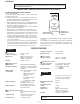
CD-BA200 NAMES OF PARTS 1 CD-BA200 Front panel 1. (CD) Disc Tray 2 2. Extra Bass Indicator 3. Spectrum Analyzer/Volume Level Indicator 4. (CD) Disc Number Indicators 5. (CD/TUNER) Memory Indicator 6. (TAPE 2) Record Indicator 7. (CD) Play Indicator 8. (CD) Music Schedule Indicators 9. (CD) More Tracks Indicator 10. Sleep Indicator 11. FM Stereo Mode Indicator 12. (CD) Random Play Indicator 13. (CD) Pause Indicator 14. (TAPE) Play Indicator 15. (CD) Repeat Indicator 16. FM Stereo Indicator 17.
CD-BA200 Front speaker CP-BA200 1. Super Tweeter 2. Tweeter 3. Bass Reflex Duct 4. Woofer 5. Subwoofer 6. Main Speaker (Woofer, Tweeter and Super Tweeter) Wire 7. Subwoofer Wire 1 2 4 3 5 6 7 1 Remote Control 1. Remote Control Transmitter LED 2 3 4 5 6 7 CD Control section 2. Disc Number Select Buttons 3. Memory Button 4. Pause Button 5. Clear Button 6. Track Down/Review Button 7. Track Up/Cue Button 8. Disc Skip Button 9. Play/Repeat Button 10. Stop Button 11.
–5– 9 8 7 6 5 4 3 2 AM 0:00 MEMORY/SET AM 12:00 TUNING/ TIME ( ) CLOCK ON/ STAND-BY POWER (Main unit operation) SETTING THE CLOCK 0:00 or ) button to adjust the hour. or ) button to adjust the The clock starts operating from "0" second. (Seconds are not displayed.) And then the clock display will disappear after a few seconds. Press the MEMORY/SET button. Press the TUNING/TIME ( or ) button once to advance the time by 1 minute. Hold it down to change the time in 5 minute intervals.
–6– Red Rojo Front speaker (Left) Altavoz delantero (Izquierdo) Blue Azul Switching between power-on and stand-by mode Cambio entre la conexión de la alimentación y el modo de reserva Never mistake the connection to the MAIN and the SUB WOOFER terminals. Wrong connection may damge the main unit or the speakers. No equivoque nunca las conexiones a los terminales MAIN y SUB WOOFER. La conexión incorrecta podría dañar el aparato principal o los altavoces.
CD-BA200 DISASSEMBLY Caution on Disassembly Follow the below-mentioned notes when disassembling the unit and reassembling it, to keep it safe and ensure excellent performance: 1. Take cassette tape and compact disc out of the unit. 2. Be sure to remove the power supply plug from the wall outlet before starting to disassemble the unit. 3. Take off nylon bands or wire holders where they need be removed when disassembling the unit.
CD-BA200 (L2) x1 CLAMP LEVER Turntable CAM GEAR RIB Disc Tray (L1) x2 Figure 8-1 (F1)x1 ø3x6mm (F1)x1 ø3x10mm CD Player Unit Figure 8-4 (E4)x1 (E2)x2 (E3)x1 (M1) x3 3 Power Supply PWB (F2)x1 Main PWB 2 1 (E2)x1 (G1)x2 ø3x10mm (F2)x3 (M1) x3 Power Supply PWB Figure 8-2 Figure 8-5 (H2)x1 (N1)x1 ø3x8mm Display PWB CD Servo PWB (N3) x2 (F3)x1 (N2) x2 (H1)x14 ø3x10mm Tape Mechanism Headphones PWB Open (J1)x5 ø3x10mm Cassette Holder (N3) x2 (K1)x1 ø3x10mm Figure 8-6 Figure 8-3 –8–
CD-BA200 (P2) x3 CD Mechanism Loading Motor PWB (P1) x1 (P1) x1 (Q1) x5 Figure 9-1 CP-BA200 STEP PROCEDURE REMOVAL FIGURE 1 Front Panel 1. Net .......................... 2. Rubber ................... 3. Screw ..................... 4. Tip .......................... (A1) x1 (A2) x4 (A3) x4 (A4) x2 9-2 2 Woofer 1. Screw ..................... (B1) x4 9-3 3 Subwoofer 1. Screw .................... (C1) x4 9-3 4 Tweeter 1. Screw .................... (D1) x2 9-3 5 Super Tweeter 1.
CD-BA200 REMOVING AND REINSTALLING THE MAIN PARTS TAPE MECHANISM SECTION TAPE2 Perform steps 1 to 7 and 9 of the disassembly method to remove the tape mechanism. Record/Playback Head How to remove the record/playback and erase heads (TAPE 2) (See Fig. 10-1) 1. When you remove the screw (A1) x 2 pcs., the recording/ playback head and three-dimensional head of the erasing head can be removesd. Erase Head How to remove the playback head (TAPE 1) (See Fig. 10-2) (A1)x2 Ø2x9mm 1.
CD-BA200 CD MECHANISM SECTION Perform steps 1, 2, 3, 11 and 14 of the disassembly method to remove the CD mechanism. How to remove the loading motor (See Fig. 11-1) Loading Moter 1. Bend the hooks (A1) x 5 pcs., to remove the loading motor. (A1)x1 (A1)x2 (A1)x2 CD Base Figure 11-1 How to remove the pickup (See Fig. 11-2) Stop Washer (B3) x2 (B1) x1 ø2.6 x6mm 1. Remove the stop washer (B1) x 1 pc., to remove the gear (B2). 2. Remove the screws (B3) x 2 pcs., to remove the shaft (B4). 3.
CD-BA200 • FM RF Signal generator: 1 kHz, 75 kHz dev., FM modulated TUNER SECTION fL: Low-range frequency fH: High-renge frequency • AM IF/RF Signal generator: 400 Hz, 30%, AM modulated Test Stage Frequency Frequency Display Test Stage Frequency Frequency Display Setting/ Instrument Adjusting Connection Parts AM IF 450 kHz 1,720 kHz T351 AM Band Coverage — 530 kHz (fL): T306 *2 1.1 ± 0.1 V 990 kHz (fL): T303 AM Tracking 990 kHz *1. Input: Antenna, *2.
CD-BA200 NOTES ON SCHEMATIC DIAGRAM • The indicated voltage in each section is the one measured by Digital Multimeter between such a section and the chassis with no signal given. 1. In the tuner section, ( ) indicates AM < > indicates FM stereo 2. In the main section, a tape is being played back. 3. In the deck section, a tape is being played back. ( ) indicates the record state. 4. In the power section, a tape is being played back. 5. In the CD section, the CD is stopped.
CD-BA200 WAVEFORMS OF CD CIRCUIT Stopped CH1=500mV DC 10:1 CH3=500mV DC 10:1 T Stopped CH1=500mV DC 10:1 500ms/div (500ms/div) NORM:20kS/s CH3=1V DC 10:1 1999/04/05 17:33:17 CH4=1V 500ms/div (500ms/div) DC 10:1 NORM:20kS/s PDO1 1 7 FDO IC2 24 1 IC2 1 3 4 8 2 IC2 23 T 3 1 CH1 v/DIV 500mV =Filter= Smoothing : ON BW : FULL =Offset= CH1 : 0.000V CH2 : 0.0V CH3 : 0.000V CH4 : 0.
CD-BA200 SW2 SW3 SW1 OPEN/ CLAMP DISC NUMBER CLOSE M3 T/T UP/DOWN MOTOR M 7 8 9 10 4 5 6 1 2 3 4 5 6 1 2 3 4 5 6 CNP12 BI4 3 CNS4 6 2 CNP4 + - 1 GND CLAMP SW 5 CD RES 4 DI CE 3 CLK 2 DO 1 DRF 5 CDINT 4 WRQ +5V(+B5) 3 CNP11 2 TO DISPLAY SECTION DGND 1 L-CH R-CH AGND TO MAIN SECTION (TO IC601) CONT2 30 CONT3 32 31 RCHO LVSS RVSS 45 46 47 48 LCHO 76 CONT4 66 CL 75 CONT7 65 CE CONT6 Q2 74 64 67 DI 40 68 DO 19 13 69 INT IC2 LC78641E
CD-BA200 FM ANTENNA AM LOOP ANTENNA +5V +B4 BF301 B.P.F 6 IC301 TA7358AP FM FRONT END 1 5 CNP301 FM RF L312 1 9 5 4 2 8 IC303 LA1832S FM IF DET./FM MPX./AM IF 23 21 SWM2 T2 PLAY IC701 54PIN SWM1 T1 PLAY IC701 53PIN SWM4 R. PLAY IC701 56PIN SWM3 F.
CD-BA200 FL701 DISPLAY +B4 1 2 3 6 ~ 14 15 ~ 20 29 ~ 53 56 57 58 Q701-Q703 Q710-Q712 JOG701 JOG +B7 RX701 REMOCON SENSOR +B6 18 60 79 SYS.
CD-BA200 CD SERVO PWB-C A 5 5 5 R51 68K TIN1 4 4 4 R52 68K FIN1 3 3 3 3 R53 68K FIN2 R54 68K TIN2 2 2 2 2 R56 68K 1 1 1 C23 0.047 IC1 LA9235M SERVO AMP. R55 68K 1 FIN1 CNP1 C 5 4 30 1 REF FIN2 C54 47/10 C C55 0.01 C7 10/16 C8 0.1 REF 2 29 +B VREF D REF PH RFSW R42 120K RF- 25 REF DH 24 6 7 EFBL 27 ODRV 22 PH/BH REF LPF 9 REF 10 11 ODRV 12 AGCON 20 REF 19 LPF 18 REF REF 13 TEST0 14 TES1 21 LPF C18 3P (CH) R5 39K R6 27K C17 0.
CD-BA200 R75 1K DO C76 100P R76 1K DI C77 100P R77 1K CL C78 100P R78 1K L62 2.2µH CE CL DI DO INT WRQ DEF RES C80 0.1 COMMAND INTERFACE 64 SUBCODE DECODE CRC 63 PW 62 SBSY 59 DATA 58 DATACK 51 50 17 18 49 48 + LPF 1BIT DAC - 19 47 46 R-CH RVSS R82 2.2K LVSS LCHO 41 EMPH DOUT C2F VDD 1K 1K PCK +B C30 0.1 C31 100/10 2 L-CH +B 4 +5V 5 +B CNP11 C83 0.022 +B 9 CONSTANT VOLTAGE +B +B L61 0.82µH R16 10K +B Q1 2SC3203Y +B ZD61 DZ3.
CD-BA200 MAIN PWB-A1 (1/2) BI601 CD_+B 7 D_GND 8 P24 1 - D CNS901 TO POWER SUPPLY PWB Q603 KTC3199GR C636 0.001 7 C621 1/50 9 10 C627 1/50 R616 2.2K R617 3.3K RIN LSEL0 8 C623 1/50 C625 1/50 11 C629 1/50 C610 19 0.1 C6 C620 0.0027 1/50 18 C622 1/50 RSEL0 17 C624 R4 1/50 16 RTRE LIN 12 L4 AUX L3 DECK R3 L2 TUNER R2 L1 CD R1 C626 1/50 C628 14 1/50 15 13 C630 1/50 M_GND 9 -15V 10 -B SP_DET 11 SP_RLY 12 +5V +B 13 C Q604 KTC3199GR CD_GND 6 C616 0.001 R622 2.
CD-BA200 601 5341 OCESSOR +B 24 +B + - VREF + - R633 33K C602 22/50 22 ROUT C614 10/50 C608 0.1 + - 21 RBASS 20 R632 R631 6.8K 6.8K CLK VDD 23 R608 10K Lch C631 390P JK601 VIDEO IN C632 390P Rch R634 33K R606 C610 3.9K 19 0.1 C612 C620 0.0027(ML) 1/50 RIN 18 C622 1/50 RSEL0 17 C624 R4 1/50 16 D601 1SS133 R3 K CHASIS C634 0.001 C626 1/50 C628 14 1/50 15 R2 R D602 1SS133 R1 13 C630 1/50 R618 3.
CD-BA200 A 1K R794 1K R740 1K R741 1K R742 R743 1K 1K R744 1K +B 53 T1 PLAY SW_A 52 51 2.2K R756 +B R733 68K R732 68K SWM1 T1 PLAY SWM3 F.PLAY PH2 13 2 1 0V T2 PLAY +5V +B T2 RUN +MTR Q707 KTC3199GR R739 470K D715 1SS133 Q706 KTC3199GR 10V +B +B R736 10K Q704 KTA1271Y 10V SOL2 SOL1 R_REC T1 RUN T1 PLAY R735 470K D714 1SS133 CNP702 FC702 PH1 SOLM2 SOLENOID SOLM1 SOLENOID SWM4 R.PLAY R738 1K C717 2.
CD-BA200 8 37 36 35 34 33 32 31 30 29 20 19 18 17 16 15 14 13 12 11 10 9 8 7 6 CLAMP SW D_GND RES OUT CD DO CD DI CD CLK DRF CD CE WRQ(DSP) 1 2 3 4 5 6 7 8 9 10 CNS703 1 2 3 4 5 6 7 8 9 10 BI703 DISPLAY PWB-A2 F F F G01 G02 G03 G04 G05 G06 G07 G08 G09 G10 G13 G11 G14 G12 P02 P01 G15 P04 P03 P05 P06 P10 P09 P08 P07 CD INT P19 12 - E TO CD SERVO PWB CNP12 G1 P5 P4 G2 C722 1/50 3 2 1 C725 0.
CD-BA200 C923 100/50 R9 0.1 ( C92 0.02 R9 10 C918 0.1 (ML) 68K R971 68K R922 4.7 -B C957 0.022 C944 220P (ML) C943 220P (ML) R966 330 -B +B +B -B +B -B +B R819 -B R806 680 (2W) 22K +B D803 TS6B04GM +B1 C803 0.047 (ML) C815 0.022 -B D804 1N4004S +B2 D807 1N4004S C805 0.047 (ML) D806 1NS4004S Q821: CONSTANT VOLTAGE REGULATOR C810 47/50 R802 10 ZD802 MTZJ6.2A R801 2.2K D810 1N4004S +B +B Q802 KTC3199GR C821 0.1(ML) 1 R816 1K R817 47K R807 220 UN_SW_5V +B +B D_GND C824 0.
+ C640 100P +B C639 100P L601 2.2mH JK670 HEADPHONES FW801 HEADPHONES PWB-A3 Q908 KTC3199GR R940 56K 5 C937 47/50 +B R945 330 (1/2W) -B +B R952 15K +B +B R954 1K 2 2 1 1 R953 68K CNP803 D909 1SS133 +B CNS803 R955 4.7K (1/2W) +B Q910 KTC3203Y C932 47/50 1 R939 56K C938 10/50 D904 R937 1SS133 1K R977 1K +B R941 56K 9GR 15 D906 1SS133 R935 10K 1 2 3 4 5 Q907 KTC3199GR D905 1SS133 C925 0.022 C927 220P C931 1/50 R933 0.
CD-BA200 C302 0.001 A C301 0.001 AM ANT. T303 C331 0.047 C330 15P (UJ) AM TRACKING fL C332 0.022 D301 1SS133 C342 0.022 VD301 SVC348S C335 560P 2 2 3 3 IC301 TA7358AP FM FRONT END 1 2 3 4 5 6 21 FM IF IN AM MIX OUT REG AM OSC IN 22 1 2 3 T351 C352 10/16 3 AM IF 8 7 9 +B C304 0.01 C305 4.7P(CH) C306 0.022 1 2 C303 10P(CH) 1 1 R302 10 FM ANTENNA AM ANTENNA 23 C350 0.022 BF301 B.P.F CNP301 D 24 C336 470P R323 68K C351 0.022 C C334 27P (UJ) AM OSC.
CF351 C374 0.015 L-CH OUT C370 1/50 C355 22P R388 3.9K C385 0.01 SD FM/AM IF CONT FM/AM MO/ST ST IND 11 R376 1K R385 5.6K R360 4.7K R370 1K DO 10 R386 22K CL 9 1K 8 R378 DI 7 1K 6 R372 5 R359 1.8K R395 47K C391 47/16 FM IN C386 330P R384 5.6K 14 13 12 IF IN 17 16 15 4 1K +B R383 5.6K 3 R373 R391 390 +B AM IN PD SWITCHING Q360 KTA1266GR CE IC302 LC72131 PLL(TUNER) +B R392 390 L351 100µH VDD AIN 19 18 R387 5.6K R377 47K R379 2.2K R380 1.5K 1K C388 0.
CD-BA200 A 22 21 20 19 18 17 16 15 14 13 12 R377 CF352 C396 R383 Q360 C313 R351 C312 R309 C353 C354 C399 C366 X351 C371 R363 C369 C367 R357 R350 R361 R364 C373 R356 R358 R370 T306 C358 R355 R362 C368 C374 C365 C332 C357 IC303 R365 C337 C342 C342 C361 C336 R323 C335 C331 C362 C308 C316 D305 C314 R336 C330 VD301 E C334 C356 24 23 22 21 20 19 18 17 16 15 14 13 R313 C388 C370 1 2 3 4 5 6 7 8 9 10 11 12 2 3 VD302 R311 R316 C323 1 L352 ZD351 CF351 VD303 C
CD-BA200 P31 10 - H TO DISPLAY PWB CNP704 P34 4 - A TO CD SERVO PWB CNP11 COLOR TABLE FC701 CNS601 1 2 3 4 5 RD WH GY WH GY MAIN PWB-A1 R140 C134 R155 C121 C127 R138 C142 E C B VIOLET GY GRAY WH(W) WHITE BK BLACK PK PINK TO TAPE MECHANISM TAPE 2 HEAD CNS102B P35 11 - F P35 10 - F CNS101B TO TAPE MECHANISM TAPE 1 HEAD R131 R139 C123 R154 R157 E C B R153 Q121 C578 P33 8 - H CNS901 TO POWER SUPPLY PWB R581 R570 Q122 R638 BLUE VL R590 ZD561 1 2 3 4 R587 C575 R586 R585 C617
CD-BA200 DISPLAY PWB-A2 A 1 2 3 FL701 RS723 RS724 RS725 R702 R705 R719 Q710 65 5 C723 R764 R770 RD0 B C E C716 D715 D714 R733 SW716 EQUALIZER Q705 SW727 PRESET UP C717 18 RS701 RD08 SW715 X-BASS/ MEMO 1 C735 R700 5 RD14 IC702 9 15 RS710 RS702 10 C738 RS708 RS709 LE RS703 RS704 E RD SW728 PLAY/ REPEAT C734 RD10 SW711 DISC3 SW710 DISC2 SW729 STOP SW709 DISC1 C719 COLOR TABLE D713 BR SW712 DISC SKIP SW713 OPEN/ CLOSE D712 RD11 RD12 12 10 8 6 4 2 13 11 9 7 5 3 1 CNP
CD-BA200 P34 5 - A TO CD SERVO PWB CNP12 CNS703 RD WH GY WH GY WH GY WH GY WH 10 9 8 7 6 5 4 3 2 1 10 1 BI703 Q709 R798 RX701 1 2 3 70 R792 R793 R794 R740 65 R741 R742 R743 60 01 55 40 45 51 50 R713 R799 C732 C728 C733 R750 R744 C715 R751 R747 C727 RD01 RD02 R749 R721 R718 SW702 CLOCK RD03 C731 R715 R712 R758 R756 R755 L701 R754 R763 R762 R761 R760 R759 R768 R767 R766 R769 R748 RS711 SW703 TIMER/ SLEEP D716 R753 R764 SW701 POWER 3 2 1 R746 R781 5 IC703 C730
CD-BA200 P35 8 - F TO POWER TRASFORMER AC POWER SUPPLY CORD (229) AC 120V, 60Hz CNS801 A 2 1 BLACK WHITE CNP801 F803 5A/125V B C831 M901 FAN MOTOR R819 C814 C938 RL801 B C E R817 Q802 T802 POWER TRANSFORMER R816 Q910 R919 R R916 C912 R994 R903 R948 C906 C902 C907 R910 R902 R995 L902 B C E Q90 R9 C903 C904 R915 R909 R913 D909 R952 B C E R9 D903 D901 C909 B C E C914 E C B C905 R955 E Q903 D815 D813 R921 C818 D812 C817 D814 Q904 R920 C901 Q901 R953 D801
CD-BA200 P35 9 - C TO POWER TRASFORMER P35 8 - A TO POWER TRASFORMER CNS802 CNS804 4 5 5 4 3 2 1 R803 CNP804 D805 C819 C828 3 CNP802 C812 D806 B C E ZD802 D807 D804 C808 C827 2 Q823 1 COLOR TABLE BROWN BR 2 3 C834 C801 R806 R924 R926 R927 R930 C928 R928 C921 C929 R807 Q906 C920 C926 C927 YELLOW GREEN BL BLUE VL VIOLET GY GRAY WH(W) WHITE BK BLACK PK PINK HEADPHONES PWB-A3 C830 JK670 HEADPHONES E C B R925 R931 YL GR R936 C925 E C B C816 C922 C923
CD-BA200 5 CD SERVO PWB-C P29 10 - A TO MAIN PWB P31 10 - A TO DISPLAY PWB CNS601 CNS703 A R71 R78 R73 R74 R75 R76 R77 R72 R19 C71 C78 C73 C74 C75 C76 C77 C72 R12 L61 R67 R68 C80 Q1 R58 C21 R13 R80 C23 C11 C12 C82 CNP3 6 5 4 3 2 1 6 5 4 3 2 1 C34 C38 9 C56 CNP4 C39 R81 C43 R83 R46 R17 R16 10 XL1 40 41 R95 R94 R48 22 C50 R20 45 C30 25 20 21 50 35 C31 Q2 65 64 60 55 30 R45 IC3 1 2 3 30 R22 35 10 15 D21 D22 IC2 20 R21 R40 40 5 70 15 24 25 3 12 11 75
CD-BA200 TAPE MECHANISM ASSEMBLY P30 2 - H TO DISPLAY PWB CNP702 TAPE MECHANISM PWB-E 13 FC702 1 13 11 9 7 5 3 1 12 10 8 6 4 2 SW SW SW PH 2 PH B A 1 + - SOLM SOLENOIDE MM1 TAPE MOTOR SOLM SOLENOIDE TAPE 1 PLAYBACK HEAD ERASE HEAD TAPE 2 RECORD/PLAYBACK HEAD CNS804 5 4 3 2 1 5 4 32 1 OR OR YL BK YL RD BL BK BL RD P33 10 - A P33 9 - A TO POWER TO POWER SUPPLY PWB SUPPLY PWB CNP804 CNP802 CNS802 3 21 T801 POWER TRANSFORMER CNS101A PK BK WH BL GR WH PK BK WH WH BL GR WH PK BK
CD-BA200 VOLTAGE IC1 PIN VOLTAGE NO. 1 1.6V 2 1.6V 3 1.6V 4 1.6V 5 1.6V 6 1.6V 7 0V 8 2.6V 9 0V 10 0V 11 0V 12 3.3V 13 1.6V 14 1.6V 15 1.6V 16 0V 17 0V 18 1.6V 19 1.6V 20 1.6V 21 1.6V 22 1.6V 23 0V 24 1.6V 25 0V 26 0V 27 0V 28 1.6V 29 1.6V 30 3.3V IC3 PIN VOLTAGE NO. 1 1.6V 2 1.6V 3 1.8V 4 2.1V 5 2.1V 6 2.1V 7 2.1V 8 0V 9 0V 10 0V 11 0V 12 0V 13 0V 14 0V 15 2.1V 16 2.1V 17 1.6V 18 4.9V 19 3.5V 20 1.6V 21 0V 22 0V 23 4.9V 24 4.9V 25 1.6V 26 2.1V 27 2.1V 28 1.
CD-BA200 TROUBLE SHOOTING When the CD does not function When the CD section does not operate when the objective lens of the optical pickup is dirty, this section may not operate. Clean the objective lens, and check the playback operation. When this section does not operate even after the above step is taken, check the following items. Remove the cabinet and follow the trouble shooting instructions.
CD-BA200 (1) Focus-HF system check Stopped CH1=500mV DC 10:1 Although a CD is inserted and the cover is closed, "NO DISC" is displayed. CH3=500mV DC 10:1 T 500ms/div (500ms/div) NORM:20kS/s FDO 1 Press the OPEN/CLOSE switch (SW1) without inserting a disc, and try starting the playback operation. TDO 3 CH1 v/DIV 500mV =Filter= Smoothing : ON BW : FULL =Offset= CH1 : 0.000V CH2 : 0.0V CH3 : 0.000V CH4 : 0.00V =Record Length= Main : 100K Zoom : 2K =Trigger= Mode : AUTO Type : EDGE CH1 Delay : 0.
CD-BA200 (2) Tracking system check Check the TE waveform at pin 18 on IC1. If the waveform shown in Figure 39-1 appears and soon after NO DISC appears. Yes The tracking servo is not activated. Check the peripheral circuits at pins 18 and 19 on IC1, pin 23 on IC2, and CNS1A/B. Yes A normal jump operation cannot be completed or the beginning of the track cannot be found. Check the around pin 23 on IC2. No "Initialization" is possible, but play is not possible. No "Initialization" is not possible.
CD-BA200 (4) PLL system check Stopped CH1=500mV DC 10:1 When a disc is loaded, start play operation. CH3=1V DC 10:1 1999/04/05 17:33:17 CH4=1V 500ms/div (500ms/div) DC 10:1 NORM:20kS/s PDO1 3 4 The HF waveform is normal, but the TOC data cannot be read. PDO2 T FDO 1 Check the PDO waveform. (Figure 40-1) CH1 v/DIV 500mV =Filter= Smoothing : ON BW : FULL =Offset= CH1 : 0.000V CH2 : 0.0V CH3 : 0.00V CH4 : 0.
CD-BA200 FUNCTION TABLE OF IC IC1 VHiLA9235M/-1: Servo Amp.
CD-BA200 IC2 VHiLC78641E-1: Servo/Signal Control (LC78641E) (1/2) Pin No. Terminal Name Input/Output Setting in Reset 1 PDO1 Output – 2 PDO2 Output – Phase-comparison output terminal for built-in VOC control. Rough servo : OFF, phase servo : ON. 3 VVSS – – Ground terminal for built-in VCO. 4 PCKIST AI – Resistor terminal for setting the PDO output current. 5 VVDD – – Power terminal for built-in VCO. 6 FR AI – 7 HFL Input – Mirror detection signal input terminal.
CD-BA200 IC2 VHiLC78641E-1: Servo/Signal Control (LC78641E) (2/2) Pin No. Terminal Name Input/Output Setting in Reset 44 LVDD – – 45 LCHO Output 1/2VDD 46 LVSS – – 47 RVSS – – 48 RCHO OUTPUT 1/2VDD 49 RVDD – – 50 XVDD – – For quartz Power terminal for quartz oscillation. 51 XIN Input Oscillation oscillation Ground terminal of 16.9344MHz quartz oscillation.
CD-BA200 IC701 RH-iX0332AWZZ: System Microcomputer (IX0332AW) (1/2) Pin No.
CD-BA200 IC701 RH-iX0332AWZZ: System Microcomputer (IX0332AW) (2/2) Pin No.
CD-BA200 DI CL VDD Yref 2 1 24 23 22 CCB INTERFACE LTRE 6 21 ROUT 20 RBASS 0.1uF CONTROL CIRCUIT CONTROL CIRCUIT LBASS 5 0.
CD-BA200 FL701 VVKBJ744GNK-1: FL Display 11G 14G 15G 13G 10G 12G 9G 1G 2G 3G 4G 5G 6G 7G 8G 9G S2 S1 S4 S3 a j h f g e r k b m n c p Dp d (1G~8G) PIN CONNECTION PIN NO. 3 2 1 CONNECTION 15G 14G 13G 12G 11G 10G 9G 8G 7G 6G 5G 4G 3G 2G 1G NP NP F1 F1 F1 PIN NO. 20 19 18 17 16 15 14 13 12 11 10 40 39 58 57 56 55 54 53 52 51 50 CONNECTION F2 F2 8 7 6 5 4 38 37 36 35 34 33 32 31 30 29 28 27 26 25 24 23 22 21 CONNECTION P12 P11 P10 P9 P8 P7 P6 P5 P4 P3 P2 PIN NO.
CD-BA200 —MEMO— – 48 –
CD-BA200 PARTS GUIDE MODEL CD-BA200 CD-BA200 Mini Component System consisting of CD-BA200 (mini unit) and CP-BA200 (speaker system). “HOW TO ORDER REPLACEMENT PARTS” To have your order filled promptly and correctly, please furnish the following information. 1. MODEL NUMBER 2. REF. No. 3. PART NO. 4. DESCRIPTION For U.S.A. only Contact your nearest SHARP Parts Distributor to order.
CD-BA200 NO. PRICE RANK PARTS CODE DESCRIPTION NO. ZD801 ZD802 ZD803 CD-BA200 INTEGRATED CIRCUITS DESCRIPTION VHEMTZJ360B-1 VHEMTZJ6R2A-1 VHEMTZJ130C-1 J J J Zener,36V,MTZJ36B AA Zener,6.2V,MTZJ6.
CD-BA200 NO.
CD-BA200 NO.
CD-BA200 NO.
CD-BA200 NO.
CD-BA200 NO.
CD-BA200 CD-BA200 701 306 A 304 306-2 701 306-1 B 704 306-3 302 C 301 702 303 D 703x4 E M1 F 305 M2 305x2 G SW4 PWB-D H 1 2 3 4 Figure 7 CD MECHANISM EXPLODED VIEW –7– 5 6
CD-BA200 CD-BA200 206 BELT CONNECTION 202 A FF/REW ROLLER ASS'Y 608x8 202-1 FF/REW ROLLER ASS'Y MM1 608 608x2 FLYWHEEL FLYWHEEL ASS'Y ASS'Y MAIN BELT TAPE1 TAPE2 608 PWB-A2 B PWB-B 608x2 608x4 605x14 608 202-2 211 214 FL701 Silicon Grease C 607 609x4 226 614x4 IC902 201-15 207 PWB-A 201-21 609 614 201-17 201-1 201-24 Silicon Grease 201-13 201-12 201-20 D IC802 201-14 IC801 227 609x3 Q823 PWB-E 201-10 201-11 228 230 607 605x5 612 PWB-A3 201 E 211 231x10 IC901 2
CD-BA200 CD-BA200 604x2 A 205 257 266 B 235 243 224 612 244 C 262 241 D 238 247 PWB-F 250x4 M3 251 259 246 239 SW3 252 255 249 E 604x2 256 CD MECHANISM SW1 SW2 248 232 253 239 239 254 260 263 F 242 239x3 258 234 204-2 240 G 204-1 264 204 204-3 PWB-C 245 H 615 1 2 3 4 Figure 9 CABINET EXPLODED VIEW (2/2) –9– 5 6
CD-BA200 CP-BA200 908x4 A 911 907 905,906 B SP3,4 915x2 903,904 910 C SP7,8 913x4 D SP1,2 915x2 SP5,6 914x4 E 912x4 909x2 901,902 BK 913x4 F 909 G SP1,2 SUPER TWEETER YL 909 BK SP1,2 SUPER TWEETER C1,2 Capacitor 3.3µF,100V RD C1,2 Capacitor 3.
CD-BA200 PACKING OF THE SET (FOR U.S.A. ONLY) Setting position of switches and knobs Tape Mechanism STOP UNIT FRONT SPEAKER CP-BA200 92L70032002510 Polyethylene Bag SPAKP0013AWZZ1 Polyethylene Bag, Unit 92L74231005300 Layer Pad Top ba ck Top Top FR SPAKA0236AWZZ Packing Add., Left/Right ON T FR ON T 92L720RBA20000 Packing Add., Rear Bottom Bottom FR ON T 92L720FBA20000 Packing Add.