Service Manual K5 CHASSIS-DVD COMBO TV
CONTENTS o o o o o o o o o o o o PAGE Safety Instructions Technical Specifications Remote Control Preparations Operating Your TV Block Diagram IC Datasheets&Specs Pin Voltages of IC’s Oscillosgraphs Of Some IC Pins Electrical Adjustments Channel Frequency Tables Spare Part List 1 2 3 4 7 8 21 22 29 31 35 38 41
1. SAFETY INSTRUCTIONS GENERAL GUIDELINES 1. It is advised to insert an isolation transformer in the AC supply before servicing a hot chassis. . exposed metallic part a return path to the chassis the reading should be between 4Mohm and the 20Mohm. When the exposed metal does not have a return path to the chassis, the reading must be infinite. 2. Potentials as high as 33KV are present when this receiver is in operation.
2. TECHNICAL SPECIFICATIONS . Power source: 220-240V AC, 50-60Hz Power consumption (nom.) : 73W Standby power consumption : 2W Aerial impedance : 75Ohm, coaxial type Receiving system 1: PAL BG PAL SECAM BG PAL SECAM BG DK PAL I VHF BAND I CH2-4 VHF BAND III CH5-12 CABLE TV S1-41 UHF BAND CH21-69 Receiving channels: 20”, 21” Audio outputs : 7W RMS at %10 THD 21” High Voltage : 25 ± 0.5 KV 21” Focus voltage : %25.6 ± %38 of EHT Grid 2 voltage : 0-1400 V Heater voltage : 6.2 ± 0.
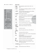
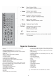
3. REMOTE CONTROL .
5
Special features • Your TV can receive stereo channels directly (NICAM optional). • Automatic tuning system with country selection. • 100 Programme Memory. • Available for Cable Channels (A decoder may be required). • Manual Fine Tuning. • Child Lock. • Return to the last viewed channel (SWAP). • Spatial Sound effect. • 16:9 picture format. • S-Video connection (optional). • Audio/Video RCA sockets (optional). • Sound adjustment using one button (Smart control). • Equalizer Sound Setup.
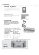
4. PREPARATIONS . MAIN SUPPLY CONNECTIONS Connect the TV mains plug into your domestic mains socket outlet (230 V 50Hz AC). Press the Program up, Program down button or Numeric Buttons on the remote handset to switch • the TV on. AERIAL CONNECTION Using a 75Ω aerial lead connect your TV to the aerial outlet in your home. BATTERY FITTING Insert the 2 AAA Batteries supplied into the compartment on the rear of the remote control, ensure you follow the polarity diagram inside the compartment.
. 5. OPERATING YOUR TV C. TUNING THE TELEVISION A. SWAP FUNCTION There are two ways of tuning your television: • Manual, where you control the tuning process or Autoprogram where the television does it all automatically. • The TV sets equipped with ATS (Automatic Tuning System) sorts the channels regarding the broadcasting system of your country (optionally). Allows you to swap between the program you are watching and the last selected program. i.e.
Please note If you do not press any buttons for 15 seconds the TV will exit the menu system. Tuning with channel numbers Enter the SETUP menu by pressing the blue button. Press the OK button to enter the CHANNEL row. In the Setup menu select PROG NO and change to P1 using the Program down button to select it and the Volume up button to change it. Use the OK button to select “S” for cable channels and “C” for terrestrial broadcast. Use Volume up button to select the channel number buttons.
Use the Program down button to select AUTOPROGRAM and the OK button. A list of Press countries will appear. Select the desired country using Program and Volume buttons. Note: TV Guide information may not have for all programmes. It depends on the broadcasting and determined by broadcasting company. Note: TV Guide is not displayed on the screen, if there is not a provider in the saved channels. When you are sure the aerial is connected properly press the OK button. Autoprogam will start.
DISPLAY INFO: If you want to see the TV Guide information automatically while changing the channels, this option should be open. In this case, if you open the provider channel Mini Guide occurs on the screen. 2-) PAT (Picture and Text) (OPTIONAL) In the double window function, you can also display the teletext screen in the second window. 3-) PIP Picture Position Change Press the POS button repeatedly until desired position is achieved. The PIP picture moves clockwise.
12
13
14
15
16
17
18
19
20
. 6.
. 7. IC DATASHEETS&SPECS 7.1)VCT 49XYI GENERAL DECRIPTION The VCT 49xyI is an IC family of high-quality singlechip TV processors. Modular design and deepsubmicron technology allow the economic integration of features in all classes of single-scan TV sets. The VCT 49xyI family is based on functional blocks contained and approved in existing products like DRX 396xA, MSP 34x5G, VSP 94x7B, DDP 3315C, and SDA 55xx.
• bass/treble or equalizer • loudness and spatial effect (e.g.
PIN CONNECTIONS AND SHORT DESCRIPTIONS NC = not connected LV = if not used, leave vacant OBL = obligatory; connect as described in circuit diagram IN = Input Pin OUT = Output Pin SUPPLY = Supply Pin Pin No 1 2 3 4 5 6 7 8 9 10 11 12 13 14 15 16 17 18 19 20 21 22 23 24 25 26 27 28 29 30 31 32 33 34 35 36 37 38 39 40 41 42 Pin Name GND VSUP8.0AU VREFAU SPEAKERL SPEAKERR AOUT1L AOUT1R AIN3L/AOUT2L AIN3R/AOUT2R AIN2L AIN2R AIN1L AIN1R/SIF TAGC VREFIF IFINIFIN+ RESETQ VSUP5.0FE VSUP5.0IF VSUP3.
43 44 45 VSUP1.8FE GND GND SUPPLY OBL SUPPLY OBL SUPPLY OBL 46 47 48 49 50 51 52 53 54 55 56 57 58 59 60 61 62 63 64 65 66 67 68 69 70 71 72 73 74 75 76 77 78 79 80 81 82 83 84 85 86 87 88 VSUP3.3FE P10 P11 P12 P13 P14 P15 P16 P17 P20 P21 SCL SDA VPROT HOUT HFLB SAFETY GNDDAC VSUP3.3DAC VSUP3.3IO GND GND VSUP3.3BE XREF VRD BOUT GOUT ROUT SVMOUT BIN GIN RIN FBIN GNDM SENSE RSW1 RSW2 EW VERTVERT+ TEST VSUP5.
7.2)TDA 8357 GENERAL DESCRIPTION The TDA8357J is a power circuit for use in 90° and 110° colour deflection systems for 25 to 200 Hz field frequencies, and for 4 : 3 and 16 : 9 picture tubes. The IC contains a vertical deflection output circuit, operating as a high efficiency class G system. The full bridge output circuit allows DC coupling of the deflection coil in combination with single positive supply voltages.
• • • Analog Voltage Range (VDD – VEE) = 3.0 to 18 V Note: VEE must be _ VSS Linearized Transfer Characteristics Low–noise – 12 nV//Cycle, f . 1.0 kHz Typical This device contains protection circuitry to guard against damage due to high static voltages or electric fields. However, precautions must be taken to avoid applications of any voltage higher than maximum rated voltages to this high–impedance circuit. For proper operation, Vin and Vout should be constrained to the range VSS _ (Vin or Vout) _ VDD.
• • • • • • • • • • • Low Power Consumption Very Low Start-up Current Soft-Start for noiseless Start-up Standby Burst Mode with and without Control Signal for lowered Output Voltages Digital Frequency Reduction in small Steps at Decreasing Load Over- and Undervoltage Lockout Switch Off at Mains Undervoltage Mains Voltage Dependent Fold Back Point Correction Ringing Suppression Time Controlled from Output Voltage Easy Design In Free usable Fault Comparator Functional Description The ICE1QS01 is optimized t
. 8. PIN VOLTAGES OF IC’S 0 45 GND Supply Voltage Analog Audio, 8.
N.C NOT CONNECTED 0 0 7 CH.2 OUT CHANNEL 2 OUTPUT 2 CH.1 IN. CHANNEL 1 INPUT 0 0 8 MUTE MUTE 3 RF RIPPLE FILTER 9 GND(OUTPUT) OUTPUT GROUND 4 GND(INPUT) INPUT GROUND 0 0 10 Vcc Vcc 25,3 8,47 5 CH.2 IN CHANNEL 2 INPUT 0 0 11 ST-BY STANDBY 16,5 0,43 6 N.C NOT CONNECTED 0 0 12 CH.
9. OSCILLOSGRAPHS OF SOME IC PINS . Note : A pattern Generator is connected to the TV (Colour Bar, sound 1 kHZ) 9.
Pin 40, Analog Video 1 Output, 15625 kHz Pin 41, Analog Video 2 Output, 15625 kHz Pin 60, Horizontal Drive Ouput, 15625 kHz Pin 61, Horizontal Fylback Input, 15625 kHz Pin 71, Analog Blue Ouput, 15625 kHz Pin 72, Analog Green Ouput 15625 kHz 32
Pin 73, Analog Red Ouput, 15625 kHz Pin 80, Sense ADC Input, 15625 kHz Pin 84,Differential Vert. Sawtooth Out(VERT-), 15625 kHz Pin 85, Differential Vert. Sawtooth Out(VERT+), 15625 kHz 9.
Pin 3, Supply Voltage, 15625 kHz Pin 4, Output B, 15625 kHz Pin 6, Flyback Supply Voltage, 15625 kHz Pin 7, Output A, 15625 kHz Pin 8, Guard Output, 15625 kHz Pin 9, Feedback Input, 15625 kHz 34
10. ELECTRICAL ADJUSTMENTS . 1. ELECTRICAL ADJUSTMENTS 1.1 Supply Voltage Adjustment Connect a digital voltmeter to the cathode of diode D610 at the AV mode of the TV and set the screen voltage to the minimum with the screen potentiometer. Adjust the main supply voltage (B+) with P601 potentiometer to the following value (after supply adjustment, readjust Screen and focus voltage). 21” : 122 VDC (for A51QDX993X030) 2.
2.3 White Balance Adjustment • • • • • • • Apply a white pattern with a pattern generator to the antenna input. Enter the Service Menu and access to VIDEO ADJ. I sub-menu Set the value of “G.CUT OFF” value to “156” and “G.DRIVE” value to “356”. Adjust red drive with“R.DRIVE” and blue drive with “B.DRIVE” . Adjust red cut off with “R.CUT OFF” and blue cut off with “B. CUT OFF” If white balance can not be adjusted properly, slightly change the values of “G.CUT OFF” and “G.DRIVE”. Exit from Service menu. 2.
BLUEBLACK : ON(blueblack acticated), OFF(Blueblack inactivated) LTI&COMB : ON; OFF CTI :ON(Colour Transition Improvement available); OFF(N/A) ADAPTIVE PKG : ON(Digital Noise Reduction available); OFF(N/A); MENU(via menu) PROTECTION : N/A(No Protection circuit); BCL ONLY(Only Beem Current Limiting available); VERTICAL ONLY( Only Vertical protection avaliable); BCL&VERTICAL(Both avaliable) PANORAMA : AVAILABLE; N/A KEYBOARD : P-P+V-V+; MENU P/V-+ GAME : AVAILABLE; N/A ALARM TIMER : AVAILABLE; N/A DVD LANG : A
2.7 Factory Settings for Service Mode Values given in Table 1 are typical values and can vary according to the CRT type. FACTORY SETTINGS FOR SERVICE MODE 21" VIDEO ADJ. I Master R.DRIVE 356 G.DRIVE 356 B.DRIVE 356 R. CUTOFF 156 G. CUTOFF 156 B. CUTOFF 156 IBRM 270 WDRM 290 SCREEN ADJ. 296 VIDEO ADJ.
11. CHANNEL FREQUENCY TABLE .
40
12.
Insertion Point C632 C633 C634 C635 C636-C637 C639-C642 C644 C646 C647-C649 C650 C651 C652 C653 C654 C655 C656 C657 C658 C659 C660 C661 C662 C664-C667 C668 C670 C701 C702 C704-C705 C706-C708 C709 C710-C712 C713 C714 C920-C923 C940-C941 D01 D102 D201 D202 D401-D405 D501 D504-D505 D508-D511 D512 D604 D605 D606-D609 D610 D611 D612-D613 D614 D615 D616 D617-D618 D619 D620 D621-D701 D702-D704 D705-D707 D708 DOWN EJECT F103 FORWARD FS601 IC01 IC101 IC201 IC301 IC401 IC501 IC601 IC602 IC603-IC604 IC605 IC606-IC608
Insertion Point L603 L701 MENU P602 PH601 PLAY/PAUSE PR/VOL Q01 Q102 R01 R102-R108 R109-R110 R113-R115 R119 R120 R121 R122-R123 R124 R125-R126 R127 R128 R129 R130 R131-R132 R133 R201-R202 R203-R204 R205-R206 R207-R209 R210 R211 R212 R213-R223 R224 R225-R226 R228 R229 R230 R233-R236 R237-R257 R258 R259 R301-R302 R303-R304 R305-R306 R307 R308 R311 R312-R312 R314 R317-R318 R319-R320 R323-R324 R325 R401 R402 R404-R407 R408-R409 R410-R413 R414-R417 R418 R419 R420 R423-R424 R425 R427-R431 R432 R434 R435 R436-R437
Insertion Point R513 R514 R515 R516-R517 R52 R521 R522 R523 R524 R525 R526 R527 R529 R531-R532 R533 R534 R537 R538 R539 R54 R540 R541 R542 R55 R56-R57 R58 R59 R601-R602 R605 R606 R608 R609 R610 R611 R617 R618 R619 R620 R621 R624 R625 R626 R627 R628 R629 R63 R631 R632 R634 R635 R636 R637 R638 R639 R640 R644 R645 R648 R649 R650 R651 R652 R654 R656-R658 R659 R660-R661 R663 R664 R665 R666 R667 R668 R702-R705 R706-R708 R709-R711 R712-R714 R715 R716-R718 R719 R720 R721 R722-R724 R725 R726-R727 R728 R729 R730-R732
Insertion Point T403-T406 T407-T501 T502 T504 T505 T506-T608 T609 T610 T701-T703 T704-T706 T707-T709 TH601 TR501 TU102 TV/DVD UP X202 X202-DVD X203 X204 X205 X301 X302 X401A X402 X402-1 X402-2 X402-X402-2 X403 X403-DVD X404 X406 X406-X402-1 X407 X407-DVD X501 X502 X503 X601 X602 X603 X603-DVD X703 X921 X922 X923 X925 X941 ZD501 ZD502 ZD503-ZD504 ZD601 ZD602 TR502 TR601 Object description TRN-CHIP BC848BLT1G SOT23 TRN-CHIP BC858BLT1G SOT23 TRN BC639 TRN.