CD-CH1000 SERVICE MANUAL No. S8070CDCH1000 AUDIO TOWER SYSTEM MODEL CD-CH1000 CD-CH1000 Audio Tower System consisting of CD-CH1000 (main unit) and CP-RW5000 (speaker system). • In the interests of user-safety the set should be restored to its original condition and only parts identical to those specified should be used. CONTENTS Page IMPORTANT SERVICE NOTES (FOR U.S.A. ONLY) ...................................................................................................... 2 SPECIFICATIONS .........
CD-CH1000 FOR A COMPLETE DESCRIPTION OF THE OPERATION OF THIS UNIT, PLEASE REFER TO THE OPERATION MANUAL. IMPORTANT SERVICE NOTES (FOR U.S.A. ONLY) BEFORE RETURNING THE AUDIO PRODUCT (Fire & Shock Hazard) Before returning the audio product to the user, perform the following safety checks. 1. Inspect all lead dress to make certain that leads are not pinched or that hardware is not lodged between the chassis and other metal parts in the audio product. 2.
CD-CH1000 CD-CH1000 NAMES OF PARTS ■ Front panel 01. 02. 03. 04. 05. 06. 07. 08. 09. 10. 11. 12. 13. 14. 15. 16. 17. 18. 19. 20. 21. 22. 23. 24. 25. 26. 27.
CD-CH1000 CD-CH1000 ■ Remote control 01. 02. 03. 04. 05. 06. 07. 08. 09. 10. 11. 12. 13. 14. 15. 16. 17. 18. 19. 20. 21. 22. 23. 24. 25.
CD-CH1000 Setting the Clock OPERATION MANUAL 5 Turn the jog dial to adjust the hour and within 2 minutes, press the ENTER button. ● When the 12-hour display is selected, “AM” will change automatically to “PM”. 6 Turn the jog dial to adjust the minutes and within 2 minutes, press the ENTER button. ● The hour will not advance even if minutes advance from “59” to “00”. ● The clock starts from “0” second. (Seconds are not displayed.) The time display will disappear after a few seconds.
CD-CH1000 ,, ,, , 1 Accessories Accesorios Remote control × 1 Controlador remoto × 1 Blue Azul Red Rojo Black Negro Black Negro Speaker wire for MAIN terminals × 2 Cable del altavoz para los terminales MAIN × 2 FM/AM loop antenna × 1 Antena de FM/cuadro de AM × 1 2 System Connections 3 Battery installation ,,, ,, ,,, ,,, ,,, ,,,,, ,,, , ,,, ,,,,, ,,, ,,,,, ,,, ,,,,, Conexiones del sistema FM antenna Antena de FM Right speaker Altavoz derecho Left speaker Altavoz izquierdo Black Negro Extra
CD-CH1000 Listening to a CD (CDs) Audición de un disco CD (CDs) 1 Press the POWER button to turn the power on. Pulse el botón POWER para conectar la alimentación. 2 Press the CD button. Pulse el botón CD. 3 Press the DISC 1 button to open the disc tray 1. Pulse el botón DISC 1 para abrir la bandeja del disco 1. 4 5” (12 cm) 3” (8 cm) Listening to a Cassette Tape Audición de un cassette 2 Press the TAPE button. Pulse el botón TAPE. Place the CD on the disc tray 1, label side up.
CD-CH1000 DISASSEMBLY CD-CH1000 Caution on Disassembly Follow the below-mentioned notes when disassembling the unit and reassembling it, to keep it safe and ensure excellent performance: 1. Take cassette tape and compact disc out of the unit. 2. Be sure to remove the power supply plug from the wall outlet before starting to disassemble the unit. 3. Take off nylon bands or wire holders where they need to be removed when disassembling the unit.
CD-CH1000 Control PWB Control Panel B (G2)x1 ø3x10mm Speaker PWB (G2)x1 ø3x10mm Power PWB Jog PWB (S1)x6 ø2.6x10mm (U1)x2 ø2.6x10mm (G1)x1 (U1)x1 ø2.6x10mm Main Chassis (S2)x1 (T1)x6 ø2.6x10mm LED B PWB CD Changer Block LED Holder Figure 9-1 Front Panel Cassette Holder Open Control Panel A (H1)x4 ø3x10mm Figure 9-4 Tape Mechanism (V3)x4 CD Switch PWB (J3)x1 Front Panel Open (J3)x1 (J1)x1 Cassette Holder Cover (V1)x4 ø2.
CD-CH1000 CP-RW5000 CD-CH1000 (CD CHANGER MECHANISM UNIT) STEP REMOVAL PROCEDURE FIGURE STEP 8-1 1 1 Top Cabinet 2 Side Panel(Left/Right) 1. Screw ................ (B1) x8 8-1 3 Rear Panel 1. Screw ................ (C1) x3 2. Screw ................ (C2) x6 8-2 4 Front Panel 1. Flat Cable .......... (D1) x1 2. Screw ................ (D2) x4 3. Socket ............... (D3) x6 8-2 5 CD Changer Mechanism 1. Flat Cable .......... (X1) x1 2. Screw ................ (X2) x2 3. Screw ..........
CD-CH1000 REMOVING AND REINSTALLING THE MAIN PARTS TAPE MECHANISM SECTION Perform steps 1 to 4 and 8 of the disassembly method to remove the tape mechanism. Record/Playback Head How to remove the record/playback and erase heads (See Fig. 11-1) 1. Carefully remove the record/playback head and erase head screws (A1) x 2 pcs. Erase Head (A1)x1 Ø2 x 9mm (A1)x1 Ø2 x 5mm Figure 11-1 How to remove the pinch roller (See Fig. 11-2) 1.
CD-CH1000 FRONT PANEL SECTION (E1)x1 ø2.6x10mm CD Changer Door Panel Perform steps 1 to 4 of the disassembly method to remove the front panel. Gear Box A How to remove the control panel motor (See Fig. 12-1) Control Panel Motor 1. Remove the control panel. 2. Remove the screws (E1) x 6 pcs., to remove the CD changer door panel. 3. Remove the screws (F1) x 2 pcs., to remove the control panel motor. (E1)x3 ø2.
CD-CH1000 CD CHANGER MECHANISM MAIN BASE PARTS ASSEMBLING/ADJUSTING PROCEDURE Work content Applied part No. 1. Motor assembly (X 2) mounting (screw x 4) Assembly fig. No. 101/129 2. MT idle gear mounting (screw x 1) 125 Fig.14 3. MT system gear assembly 123/124/126/127 Fig.14 4. STB/tray drive system gear and others assembling/ mounting (screw X 3) 137/138/145/146 (153)/147/148 Fig.14 5. Tray big gear assembly 131 Fig.14 6. T.M SW PWB mounting (screw x 3) 7.
CD-CH1000 112 STB DRIVE GEAR R (ASSY) 148 STB GEAR D 101 MAIN BASE 103 STB HOLDER 124 129 129 123 126 110 STB DRIVE GEAR A 123 Mark position 125 127 145 STB GEAR A 153 STB GEAR ANG. 146 STB GEAR B 147 STB GEAR C 110 STB DRIVE GEAR A 111 STB DRIVE GEAR L (ASSY) 137 138 TRAY GEAR C TRAY IDLER GEAR 131 TRAY BIG GEAR After assembly TRAY BIG GEAR, turn it in the arrow direction.
CD-CH1000 124 129 129 123 126 123 125 127 Mark position * This position becomes the reference (stock) position of the tray. 145 132 TRAY GEAR A 146 147 The hole must align. It must not rotate in contact with the peripheral (hatched) part of 131. 110 133 TRAY GEAR B 111 Direct the recess part (trapezoidal side) of the axis 135 in this direction.
CD-CH1000 Mark position (Assemble the mode big gear in this position.
CD-CH1000 37° Mark position 128 142 LIFT GEAR A 132 133 145 130 TRAY DRIVE GEAR F 146 110 147 111 141 143 TRAY JOINT GEAR F (CHANGE BOX L ASS'Y) ASSEMBLING POSITION LIFT CAM 144 140 LIFT CAM Scale: 2 magnifications Assembling procedure 1. Turn the mode big gear approx. 37 degrees in the arrow direction. 2. Assemble the change box L ass'y. Note: At this time, the tray joint gear F must be located in the position shown in figure. Moreover, the gear must be engaged securely. 3.
CD-CH1000 180 TOP PLATE F Mark position 142 LIFT GEAR A 132 133 145 130 146 110 147 135 111 141 143 140 144 STB HOLDER HEIGHT ADJUSTING METHOD When the height of STB holder is high, (Decrease the clearance.) When the height of STB holder is low, (Increase the clearance.) Bend this part. 240 OS LEVER Adjusting procedure 1. Turn the mode big gear approx. 37 degrees in the arrow direction. 2.
CD-CH1000 Mark position Be sure to assemble the tray into this position. 191~196 TRAY1~TRAY6 Insert it along the guide of the change box. 142 LIFT GEAR A 132 133 145 ,,,, ,,,, ,,,, 146 110 147 130 TRAY No.1~6 Rear surface: Stamped. Note: During insertion, don't mistake No. 135 111 141 143 140 Rear side 144 Tray installing method: (After adjusting the height of the STB holder) ,, ,, ,, 1. Turn the mode big gear to the mark position to lower the STB holder to the bottom area. 2.
CD-CH1000 ADJUSTMENT MECHANISM SECTION TUNER SECTION • Driving Force Check fL: Low-range frequency fH: High-range frequency Torque Meter Specified Value Play: TW-2412 • AM IF/RF Signal generator: 400 Hz, 30%, AM modulated Over 80 g • Torque Check Frequency Frequency Torque Meter Play: TW-2111 30 to 60 g. cm Fast forward: TW-2231 60 to 120 g.cm Rewind: TW-2231 60 to 120 g.
CD-CH1000 TEST MODE Outline While the unit is turned off, press the POWER key while holding down the VOLUME-DOWN and PANEL OP/CL keys to enter the test mode selection mode. Then, the unit is started, the panel is opened, and the microcomputer's version/destination/span is displayed. If the following data is entered from the keyboard while in the test mode selection mode, the unit directly enters the specified test mode. This operation is applied to the main unit's keys only.
CD-CH1000 2. Soft reset Purpose: To initialize the unit. Function: To initialize all functions. Operation: "ALL CLEAR" is displayed, all functions are initialized, and the unit is turned on. To exit the test mode When the initialization through soft reset is complete, the unit is turned on. Table Character display for test mode 2 Character display Item Reset operation display Type Auxiliary display Operation 1 2 3 4 A L L 5 6 7 8 : 9 10 Auxiliary display Note C L E A R 3.
CD-CH1000 (3) Step 3 mode Performs focus search and turns on the focus servo. Focus search is repeated until it is brought into focus. Display "T3___________0:00" The keys you can press here and the resulting operations are as follows: "POWER" ........... The test mode is turned off, the power is turned off, and the unit is placed in the normal standby mode. "FF/FWD" ........... While holding down this key, the pickup is moved outward. "REW/REV" ........
CD-CH1000 Table 24. TEST-TuSet preset frequencies CH BAND 1% 2 3 4 5 6% 7 8 9 10 11-40 Unused channels are indicated with "_". '%' indicates the last channel for each band. All FM bands are preset to FM monaural. U.S.A. FM FM 87.5 MHz FM108.0 MHz FM 90.0 MHz FM106.0 MHz FM 98.0 MHz AM AM 530 kHz AM1720 kHz AM 600 kHz AM1400 kHz AM 990 kHz Extension cable Type 1. 33 Pin extension flat cable, 500mm Part No.
CD-CH1000 NOTES ON SCHEMATIC DIAGRAM • Resistor: To differentiate the units of resistors, such symbol as K and M are used: the symbol K means 1000 ohm and the symbol M means 1000 kohm and the resistor without any symbol is ohm-type resistor. Besides, the one with “Fusible” is a fuse type. • Capacitor: To indicate the unit of capacitor, a symbol P is used: this symbol P means pico-farad and the unit of the capacitor without such a symbol is microfarad.
CD-CH1000 SWITCHING Q351 TUN_L 13 MO/ST 14 L-CH OUT (FM/AM) 12 PHASE VSM TUN_R 15 R-CH OUT A_+B X351 456kHz IC303 LA1832S FM IF DET./FM MPX.
PB_MUTE l Q507 REC_R-CH Q508 Y X W V U T S R Q O 8 4 7 1 – 2 3 + + – 5 6 VSM D_GND C2B_DO C2B_CL C2B_DI C2B_CE REC_L-CH +B -B NC NC A_GND n TAPE_R m TAPE_L REC_L-CH IC503 NJM4558M MOTOR DRIVER REC_L-CH CD_L L1 12 TUNER_R 14 R2 TUNER TAPE_R 15 R3 DECK L3 10 AUX_R 16 R4 AUX L4 9 18 IC502 RIN – + + – VREF LTRE LBASS LOUT + – 22 LIN – + RTRE IC502 20 RBASS LC75341 ROUT AUDIO R_CH 21 PROCESSOR – + +B AUX_L CD_R A_GND 7 REC_L-CH CD_L 6 5 AUX_R R-CH JK501 AUX IN L-CH
CD-CH1000 +B 26 LCD DB7 TO CD PWB 9 8 7 6 5 4 3 2 1 41 XT2 42 XT1 T-SOL T-MOTOR DEST_OUT1 A-FP SW CAM SW DEST_OUT2 CD CD CD CD CD C FH C FH C FH A-SW D FH A-SW E LCD-E LCD-RW TUNER CL TUNER DI AVref1 LEVEL_R AVSS KEY 4 KEY 3 KEY 0 KEY 1 KEY 2 AVDD A Vref 0 48 PROTECT VSM 47 SYS STOP CD 81 FH T-SW A 49 SP RLY 50 POWER KEY LEVEL_L 46 JOG-B 50 FH 83 FH T-SW C 82 FH T-SW B 44 REMOCON 45 JOG-A 49 B-FP SW CE CST SW DEST_IN SPAN CD MUTE CLK DATA LCK1 LCK2 43 RESET
CD-CH1000 +B +B +B IC912 BU2092F INPUT/OUTPUT EXPANDER 18 VDD VSS 1 __ 17 OE DATA 2 16 Q11 CLOCK 3 15 Q10 14 Q9 13 Q8 12 Q7 11 Q6 10 Q5 T-SOL T-MOTOR DEST_OUT1 DEST_OUT2 7 6 5 4 3 2 1 Q1 6 Q723 REC MUTE 99 Q721 SW710, SW730~SW735 +B FH M B- 98 FH M B+ 97 LED_EG LED_1 LED_2 LED_3 LED_4 LED_5 +B FH A-SW A FH A-SW B FH A-SW C FH A-SW D LED754 LED755 83 82 81 SW761~SW764 A_+B KEY2 KEY3 KEY4 D_GND JOG-A JOG-B Q955 Q954 2 +B CNP934 1 2 3 4 5 6 +B 7 1 2 3 4 5 6 7 8 KEY4 KEY3 KEY2 A_+
CD-CH1000 Q200 MO200 FAN MOTOR + Q212 JK701 HEADPHONES FAN MOTOR DRIVER M SO201 + Q210 + RY202 + + SP L-CH GND MAIN SP L-CH SP L-CH SO201 GND SPEAKER SP L-CH SUB TERMINALS WOOFER SP R-CH GND SP R-CH SP R-CH GND MAIN SP R-CH Q209 AC POWER SUPPLY CORD AC 120V, 60Hz RY801 F807 5A 125V RY201 M+10V Q211 -B Q206 +B Q205 Q201 1 IC802 KIA7810AP VOLTAGE REGULATOR IC802 7 – 3 4 – 5 -B Q809 6 A_GND M_+10V -B A_+10V A B C D -8V +B FAN_CTL SP_DET SP_RLY UN_SW 5V +B D_GND D_GND AC_
FOO TRO VREF RFGC TEBC SEL AVDD3 FMO DMO DVSS DVDD TESIN XVSS XI XO XVDD CD/CD-RW_SEL IC2 TC9490F SERVO/SIGNAL CONTROL – 31 – PDO PVDD /UHSO /HSO SBSY SFSY DATA CLCK SBOK DVSS DVDD IPF DOUT AOUT LRCK BCK CNP1 TO MAIN PWB Figure 31 BLOCK DIAGRAM (6/6) IC6 NC NC IC6 TA2147F SERVO PRE AMP.
CD-CH1000 AM FM/AM LOOP ANTENNA FM AM SIGNAL FM SIGNAL 1 2 3 CNP303 1 2 3 A C321 100/16 C345 0.022 C346 0.022 0.1V 1.8V Q302 KTC3194 Y OSC BUFF C318 100P(CH) C T311 T312 FM IF VD303 SVC211C C2B_DO R371 R399 10K 0V 4.7V D R373 1K 4.7V 4.7K Q371 KTA1266 GR SWITCHING R374 1K C311 100P(CH) C312 100P (CH) C382 15P(CH) C310 100P (CH) R372 1K D352 DS1SS133 VDD 17 C397 L351 100µH 9.2V 11 ST IND IF IN 12 0V R376 1K 3 CF302 FM IF 10.7MHz R323 68K R378 82K +B R351 5.6K C351 0.
CD-CH1000 TO TUNER SECTION P32 1-G TUN_L A_GND TUN_R A_+B C2B_CE C2B_DI C2B_CL C2B_DO D_GND L M N K H E G F I C562 0.1 C599 0.001 CHASSIS GND J MAIN PWB-A (2/3) VSM JK501 AUX IN L-CH R-CH D508 DS1SS133 D507 DS1SS133 R550 39K R549 39K L502 2.2µH R547 2.2K R548 2.2K C573 2.2/50 R591 47K R592 47K C574 2.2/50 Y AUX_SEL X VSM W C2B_DO V C2B_CE U C2B_DI T C2B_CL S D_GND R S-MUTE Q CD-R_SEL P CD_MUTE O PB_MUTE NC S-MUTE +B R526 1K C529 10/50 5V R528 C510 2.2K 10/50 C512 5V 0.
CD-CH1000 C950 150P (CH) R1031 EX-DATA 1K EX-CLK R1007 1K LCK1 R1008 1K A C958 390P C957 150P (CH) 0V 0V 0V 0V 1.
CD-CH1000 C958 390P 7 P ) 0V 0V 0V 0V 1.1V 1 2 3 4 5 6 7 8 0V 9 41 +B VDD 18 5V IC912 BU2092F INPUT/OUTPUT EXPANDER C970 0.1 VSS 0V DATA OE 17 0V R1032 1K SW12 16 CLK 0V R1052 1K LCK SW11 15 2.8V R1051 1K NC SW10 14 0V R1050 1K NC SW9 13 0V R1023 1K NC SW8 12 NC SW7 11 P_CONT R1048 CD-R_SEL SW5 10 LCD_RESET 10K MAIN PWB-A (3/3) DIG_SEL AUX_SEL FAN PNL_OP PNL_CL R1027 10K R1026 10K R1024 10K +B C975 1/50 C974 0.1 C976 0.
CD-CH1000 BI703B BI703A DISPLAY PWB-B1 R744 LED724 LED723 LED722 150 +B 1 +B 1 2 2 0.8V LED721 LED720 LED719 LED718 LED717 LED716 R741 150 R743 150 A R727 LED706 LED705 LED704 150 R732 LED709 LED708 LED707 150 LED701 ~ LED709: L1154GDA LED716 ~ LED724: L1154GDA R724 LED703 LED702 LED701 150 +B LED A PWB-B2 Q707 KTC3203 Y 0.2V C716 2.2/50 CNP701 LCD720 LCD DISPLAY 5 +B L703 2.2µH C705 10P 2 3 4 5 C704 10P VLCD 5V VSS 0.1V VDD 5V SCL 3.1V SDA 3.4V 1 R749 1K R748 10K 0.
CD-CH1000 BI740B BI740A MOTOR PWB-B7 1 2 3 1 2 3 SW705 OPEN/CLOSE CNS741 BI741 TO MAIN PWB CNP933 P35 12-H 1 2 3 4 5 1 2 3 4 5 OPEN_SW CLOSE_SW D_GND MOTOR_+ MOTOR_– SWITCH PWB-B8 + M – C715 0.1 MO700 CONTROL PANEL MOTOR FM SIGNAL HEADPHONES PWB-B9 TO POWER PWB CNP207 P41 12-B CNS730 BI730 1 2 3 4 JK701 HEADPHONES RA711 150 1 2 3 4 L705 2.2µH RA710 150 CONTROL PWB-B4 LED776 K5052UL R787 1K CNP775 CNS773 2 1 CNS772 BI772 1 1 2 2 3 3 4 4 5 5 6 6 BI771A 4 3 2 1 2 CNP934 R755 1.
CD-CH1000 A B CD SIGNAL C CNP1 5 IC2 TC9490F SERVO/SIGNAL CONTROL 13 C18 R29 100K R30 12 2.2M PDO /HSO /UHSO PVDD 17 5V 1.6V NC 3.3V NC NC 1V 0V C27 0.0047 C21 0.001 1.7V 0.033(ML) TEZI 32 1.7V TEI 31 0.7V SBAD 30 1.7V C22 FEI 29 0.033(ML) 1.7V RFRP 28 1.7V RFZI 27 1.7V RFCT 26 3.3V AVDD 25 1.7V C23 0.01 RFI 24 1.6V C24 SLCO 23 0.0027 0V AVSS 22 1V VCOF 21 1.7V C25 0.01 PVREF 20 3.3V LPFO 19 1V LPFN 18 0V C26 TMAX 1 2 3 4 5 6 7 8 9 10 11 12 13 14 15 16 TP1 TP2 TP3 TP4 R25 5.
CD-CH1000 C95 100P C94 100P GND(D) CANA_A CANA_B CANA_C CANA_D CANA_E CANB_A CANB_B GND(D) CAMA_A CAMA_B CAMA_C CAMA_D CAMA_E CAMB_A CAMB_B 1 2 3 4 5 6 7 8 R78 8.2K IC5 BA5939S FOCUS/ TRACKING/ SPIN/ SLED DRIVER 0.3V 4V 4V Q5 4V KRA102 M SWITCHING C45 C48 470/10 100/10 R49 1.2K R50 1.2K +B R47 8.6V 0V 7V 8.6V 0V 4.3V 4.3V 0V 0V C46 0.022 8.6V 10K 1.7V 1.7V 4V 4V 4V C38 10/50 C49 0.1 Q1 2SC1740 R R35 1K R36 2.2K R37 33K 24 10 8 IC6 TA2147F SERVO PRE AMP. 2.7V C67 0.
CD-CH1000 C 10 11 12 13 14 15 D CNP807 1 2 3 4 5 6 7 8 TO MAIN PWB BI950 P35 7-H FAN_CTL SP_DET SP_RLY UN_SW 5V D_GND D_GND AC_RLY CTL -8V Ch1 Out 31V +Vcc 8 0V 0V -30V 30V C234 1/50 4.6V C242 C2 10/50 10/ R256 0.1(1W) R260 1K C240 0.022 0V R258 0V 10K Q204 KTC3199 GR C251 47/50 D204 DS1SS133 R246 820 R261 56K 0V 4.6V 0V Q205 KTC3199 GR Q206 KTC3199 GR -0.2V -0.2V -0.2V R205 56K R209 C205 1K 15P -0.2V R203 820 0V -36V 0V C250 0.
CD-CH1000 POWER PWB-D1 (1/2) Ch2 -0.2V 0V Q210 KTC3199 GR R284 1K 8.2V R299 3.9K 0V 0V R283 470K C257 10/50 Q212 2SA562 Y +B 0V 0.1V Q209 KTC3199 GR R253 R276 22K R275 22K R270 330(1/2W) D207 DS1SS133 R271 4.7(1/2W) FROM HEADPHONES PWB CNS730 P37 8-C + + - 1 2 3 4 5 6 7 8 C254 3300/63 C255 2200/50 + SP L-CH GND MAIN SP L-CH SP L-CH SO201 GND SPEAKER SP L-CH SUB TERMINALS WOOFER SP R-CH GND SP R-CH SP R-CH GND MAIN SP R-CH BI201B C245 0.1(ML) R272 4.7(1/2W) BI201A C246 0.
CD-CH1000 FROM CNS940 P35 9-H MAIN PWB P40 1-F TO POWER SECTION CNP102 A B C D A_+10V A_GND M_+11V BIAS_GND 1 2 3 4 5 6 7 8 REC_CONT REC_BIAS +B C134 47/25 BIAS OSC. Q116 KTC3203 Y 0V 1 C141 1/50 1 0V 11.3V +B 0V 6.8V 13 Vcc GND 12 L104 330µH 0V R148 4.7 0V C133 0.039(ML) C137 0.0082 R143 82 R141 R139 C135 47K 22K 0.047(ML) Q114 SWITCHING 2SA1015 GR 0V C131 4V 0V 14 RIPPLE ALC 11 22/50 3.7V 3.7V R136 10K 0V C130 1/50 C138 0.0033 R109 15K C124 0.022 16 R134 100 R132 1.
CD-CH1000 LED A PWB-B2 LED708 LED709 RD LED707 LED706 LED705 LED704 2 LED724 BI703B R732 LED723 LED722 R744 R727 LED718 LED717 LED702 LED703 1 LED721 LED716 R724 R741 LED701 LED720 LED719 R743 WH RD WH DISPLAY PWB-B1 2 C716 1 BI703A 6 R719 R718 L704 BI702 WH GY WH GY WH RD L703 1 R788 C706 C705 C704 CNP701 4 E C B Q707 5 3 2 1 R749 R748 RD WH GY WH GY WH P46 5-A CNP970 6 5 4 3 2 1 5 TO MAIN PWB 1 CNS702 FFC970 11 1 CNP935A TO MAINPWB P46 2-A 1 3 5 7
CD-CH1000 A CD SWITCH PWB-B3 LED759 SW730 CD1 PLAY SW701 POWER R701 R708 R726 Q725 3 2 1 B SW720 CD1 EJECT R707 RX701 LED758 R711 1 2 3 SW731 CD2 PLAY R702 R710 BI720 R750 C709 LED757 C707 C703 SW732 CD3 PLAY 5 R720 SW723 CD4 EJECT R721 10 9 3 2 1 Q720 SW733 CD4 PLAY R792 IC702 18 15 Q721 CNP721 1 2 3 4 5 6 LED756 R791 11 R714 R715 1 E SW722 CD3 EJECT R713 D SW721 CD2 EJECT R703 1 R747 CNP931 P46 2-A RD WH GY WH GY WH GY WH GY WH GY LED731 TO MAIN PWB CN
CD-CH1000 CONTROL PWB-B4 SW758 STOP JOG PWB-B5 R777 R781 R779 LED773 LED776 R783 SW778 ENTER R773 R764 SW756 PLAY/ PAUSE R769 R758 SW755 FAST FORWARD SW753 FAST REVERSE LED775 JOG701 JOG DIAL LED774 SW776 MENU R755 R752 SW750 RECORD PAUSE R766 R775 R771 SW751 CLEAR SW752 MEMORY SW774 DISPLAY SW772 EQUALIZER MODE SW770 PLAY MODE SW764 CD SW773 X-BASS SW761 AUX R753 SW762 TUNER R754 1 R757 R760 C713 R761 BI773 1 1 1 4 BI770 BI771B 2 1 4 7 CNS772 CNS773 6 5 4 3 2
CD-CH1000 TO TAPE MECHANISM PWB P43 11-F FROM JOG PWB P45 11-E CNS770 FROM DISPLAY PWB P43 7-F CNS702 FROM CD SWITCH PWB P44 1-D CNS720 A FROM MOTOR PWB P45 8-F CNP741 TO POWER PWB P51 12-E CNP807 FFC970 1 11 8 7 6 5 4 3 2 1 BI950 B Q905 3 C Q907 R36 C958 R1051 C950 R1023 C714 1 5 9 IC912 15 IC701 7 6 5 4 R763 18 10 3 2 1 R1027 R1050 R768 C936 R364 E CNP933 1 2 3 4 5 R1126 C37 C957 R1141 9 8 R1109 R1105 2 Q908 C901 C999 Q909 R1014 B R1015 C970 C995 C R362 1
CD-CH1000 CNP303 D304 D303 D301 D302 C330 C323 C306 L312 C308 D310 C309 C314 C315 R322 Q302 R311 VD302 R313 C317 C316 C345 C327 C390 C318 C313 C347 C303 C304 C305 C342 C346 R351 CF302 C363 C350 3 2 1 R352 D306 D311 C301 D312 X352 11 10 9 8 7 6 5 4 3 2 1 IC302 R371 R372 C312 C311 R373 R374 C310 D352 R376 R395 R383 R399 C397 12 13 14 15 16 17 18 19 20 21 22 C355 Q360 B C E C380 C389 R384 R379 R393 R377 C384 E C B L351 C387 C382 C341 R382 C391 R385 C392
CD-CH1000 TO MAIN PWB CNP901 P46 6-H FFC901 1 CD PWB-C 33 C49 CNP1 C E C46 R77 TP10 R72 R46 R45 R78 R50 Q4 B C E CNP5 R52 C47 5 24 R40 R53 1 1 2 3 4 5 6 7 8 C32 R55 C43 C44 R56 CNP7 R39 B C E C98 C60 C58 C33 C59 Q1 1 R57 2 3 4 5 6 7 CNP3 4 3 2 1 F 13 8 8 9 10 12 5 7 6 4 FW2 1 FW3 8 G R31 C29 R35 R27 10 20 R37 C36 C34 TP6 IC6 15 C41 C30 R49 TE 3 2 14 15 4 11 1 12 13 C40 C23 C20 TP14 C42 C99 C95 C96 C97 C25 R32 C94 1 2 3 4 5 6 7 8 CNP2
CD-CH1000 MOB2 TRAY MOTOR MOB1 MAIN CAM MOTOR CNS4 YL 4 OR 3 RD 2 BR 1 NM2 SLED MOTOR + CNS6B BL GY GY GY GY GY 1 2 3 4 5 6 1 2 3 4 5 6 NM1 SPINDLE MOTOR CNP6A 1 2 3 4 5 6 - CNS6A NSW1 PICKUP IN + 1 2 3 4 5 6 7 8 CNS5B RD GY GY GY GY GY GY GY CNS7A 1 2 3 4 5 6 7 4 - CNS5A 1 2 3 4 5 6 7 8 CD MOTOR PWB-E CNS7B RD WH WH WH WH WH WH 1 2 3 4 5 6 7 PICKUP UNIT SWB103 DISC DETECT3 COLOR TABLE BR SWB102 DISC DETECT2 1 SWB101 DISC DETECT1 RED 7 6 5 4 3 2 1 OR ORANGE YL YELLOW 8 7
CD-CH1000 SO201 SPEAKER TERMINALS MAIN SUB WOOFER MAIN R-CH GND R-CH GND L-CH GND L-CH GND A SPEAKER PWB-D3 L201 B L202 L204 BI201B 1 8 WH GY WH GY WH GY WH RD L203 AC POWER SUPPLY CORD AC 120V, 60Hz BK WH C 1 2 BL GY WH GY WH RD RD CNS808 5 4 3 2 1 D 2 RD WH GY WH GY CNP801 1 T801 MAIN POWER TRANSFORMER 1 5 BL BI808 T802 SUB POWER TRANSFORMER C836 F806 4A 125V C834 F807 5A 125V E RD RD 1 BL BK BL RD 2 3 4 5 D816 F805 4A 125V F C832 CNP802 4 3 CNS804 2 CNP803 C
CD-CH1000 POWER PWB-D1 C231 C203 R234 C225 R237 C221 C226 R233 1 2 3 4 5 6 7 8 R211 C248 C207 8 7 6 5 R221 R235 C213 R277 C229 C219 R227 C211 TO MAIN PWB BI960 P47 8-A C217 C227 R203 C247 IC203 R241 R239 D201 R228 1 2 3 4 CNP806 FR214 C218 1 2 3 4 5 6 7 8 9 10 11 12 13 14 15 R217 D205 DZ803 R813 C820 BI950A P46 6-A WH PK R144 R134 Q210 Q119 2 1 3 R200 DZ201 1 2 C141 Q120 3 1 2 CNP102 C140 R104 R154 R156 R150 R126 R124 C258 R207 B CE R299 B CE Q212 R130 R129
CD-CH1000 WAVEFORMS OF CD CIRCUIT STOP NO DISC FOCUS SEARCH 1 PLAY FOO IC2 33pin 12 2 IC5 2pin 3 TMAX IC2 17pin FO+ 13 SBOK IC2 8pin FO- IC5 1pin 14 DMO IC2 41pin 0.2µs FOCUS SEARCH 0.2µs STOP TOC IL 6 4 TEI IC2 31pin SEL IC2 38pin 5 PLAY 11 TRO IC2 34pin FEI IC2 29pin 6 15 TEI FMO IC2 40pin IC2 31pin 0.2µs 0.2µs STOP 5 PLAY CUE 6 FEI IC2 29pin 7 11 SBAD TRO IC2 34pin IC2 30pin 8 TEI IC2 31pin RFO IC6 22pin 15 FMO IC2 40pin 0.2µs STOP 5 0.
CD-CH1000 TROUBLESHOOTING When the CD does not function When the CD section does not operate when the objective lens of the optical pickup is dirty, this section may not operate. Clean the objective lens, and check the playback operation. When this section does not operate even after the above step is taken, check the following items. Remove the cabinet and follow the troubleshooting instructions.
CD-CH1000 Check in the CD test mode. STEP 1 Does the display "E-CD01" appear? Yes No Does the pickup move to the inner/outer position using the 'UP'/'DOWN' key? Check the line of PU-IN SW. Check from pin 2 of CNP6 via pin 25 of CNP1 to pin 94 of IC901. No Check the line of the slide control. Check from pins 3 and 4 of CNP6 via pins 17, 18 and 22 of IC5 to pin 40 of IC2. No Check from pins 7 and 8 of CNP5 via Q4 and pins 6 and 7 of IC6 to pin 38 of IC2.
CD-CH1000 FUNCTION TABLE OF IC IC2 VHiTC9490F/-1: Servo/Signal Control (TC9490F) (1/2) Pin No. Function Terminal Name Input/Output 1 BCK Output Bit clock output terminal. 32fs, 48fs or 64fs can be selected by command. 2 LRCK Output L/R channel clock output terminal. L channel: "L", R channel: "H". the output polarity can be inverted by command. 3 AOUT Output Audio data output terminal. MSB/LSB fast can be selected by command. 4* DOUT Output Digital out output terminal.
CD-CH1000 IC2 VHiTC9490F/-1: Servo/Signal Control (TC9490F) (2/2) Pin No. Function Terminal Name Input/Output 39 AVDD3 40 FMO Output — Feed equalizer output terminal. Analog 3.3V power supply terminal. 41 DMO Output Disc equalizer output terminal. 42 VSS3 — Digital GND terminal. 43 VDD3 — Digital 3.3V power supply terminal. 44 TESIN Input 45 XVSS3 — 46 XI Input 47 XO Output 48 XVDD3 49 DVSS3 50 RO 51 DVDD3 52 DVR 53 LO 54 DVSS3 Test input terminal.
CD-CH1000 IC6 VHiTA2147F/-1:Servo Pre Amp. (TA2147F) Pin No. Terminal Name Function Input/Output 1 VCC — 2 FNI Input 3.
CD-CH1000 IC6 VHiTA2147F/-1:Servo Pre Amp. (TA2147F) PEAK GVSW 13 20K 12 RFDC 15K 50K 20K 20µ VRO 14 11 TEO 40K 20K 10p FEO 15 20K 15K 10 TEN 20K 40K 10p FEN 16 9 TEB 20K 50u 12K 1.3V 2K 50K 8 SEL RFRP 17 12K 20K 1K BOTTOM PEAK RFRPIN 18 7 LDO 14K 2K 40K 6 MDI RFGO 19 240K 15p RFGC 20 x0.5 x2 5 TNI 1 x0.
CD-CH1000 IC901 RH-iX0353AWZZ: System Microcomputer (IX0353AW) (1/2) Port Name Pin No.
CD-CH1000 IC901 RH-iX0353AWZZ: System Microcomputer (IX0353AW) (2/2) Pin No.
CD-CH1000 IC702 VHiBU2092F/-1: Input/Output Expander (BU2092F) Pin No.
CD-CH1000 LCD DISPLAY LCD720: RUNTZ0020AWZZ L R Recommended Circuit for Contrast adjustment VDD R1 LCD PANEL VLCD VR R2 80seg+4com VSS SCL R1+VR+R2=20k Ohm SDA VSS VDD VLCD PCF8533U/2 SA0,A0,A1,A2 connect to VSS R tr/2Cb MPU Pin No.
CD-CH1000 PARTS GUIDE AUDIO TOWER SYSTEM MODEL CD-CH1000 CD-CH1000 Audio Tower System consisting of CD-CH1000 (main unit) and CP-RW5000 (speaker system). “HOW TO ORDER REPLACEMENT PARTS” To have your order filled promptly and correctly, please furnish the following information. 1. MODEL NUMBER 2. REF. No. 3. PART NO. 4. DESCRIPTION For U.S.A. only Contact your nearest SHARP Parts Distributor to order.
CD-CH1000 NO.
CD-CH1000 NO.
CD-CH1000 NO.
CD-CH1000 NO.
CD-CH1000 NO.
CD-CH1000 NO.
CD-CH1000 NO.
CD-CH1000 NO.
CD-CH1000 CD-CH1000 306-2 A 306 306-1 306-3 701 704 B 701 304 C 302 301 702 D 303 703x2 E NM1 F 307 NM2 308 305x2 G NSW1 H PWB-E 1 2 3 4 Figure 9 CD MECHANISM EXPLODED VIEW –9– 5 6
CD-CH1000 CD-CH1000 803x3 803x2 114 117 803x2 A 803x3 806 148 B 802x3 116 149 118x2 146 106x6 126 803x2 802x2 107 152 147 806 PWB-F 145 124 115 C 125 134 143 102 803 144 803 138 123 127 142 120 805 140 137 805 141 804 133-1 141 807 132 D 139 131 130 121 119 133-2 803x2 133 E 804 119 113 136 121 128 129 135 122 805 112 F 123 111 PWB-G 133-3 151 101 104 110 105 G 109 801x4 MOB1 PWB-C MOB2 803x2 803x3 802x2 808x4 803 108 H 805x4 CD MECHAN
CD-CH1000 CD-CH1000 201-4 201 201-30 A PWB-B2 201-3 201-25 201-31 201-34 609x4 BELT CONNECTION B FF/REW Belt PWB-B1 FF/REW Clutch 201-32 603x4 201-38 TAPE MECHANISM 201-37 LCD720 612x4 602 Flywheel Tape Main Belt Motor 201-23 C 208 PWB-B3 608x6 250 201-12 250-1, 250-2, 250-3, 250-4, 250-5, 250-6, 201-13 619 250-7, 250-8 201-24 201-1 D 201-16 201-14 201-26x6 201-11 201-15 201-10 201-9 201-8 201-7 201-6 201-5 E 614x2 607 201-29 201-33 205-4 610 205-10 201-17 201-27 201-18
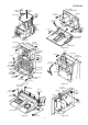
CD-CH1000 CD-CH1000 617 204 618x2 A 617x5 618x2 605 PWB-D1 236 239 219 614 216 605 B 617x2 PWB-D3 IC802 Q809 Q805 207 IC202 IC201 615x3 232 617x4 231 C 617x4 616x4 230 Silicon Grease 617 202-2 615x3 604x4 M0200 238 228 202-1 202 225 D 227 614 x2 226 241 210 211 620x2 PWB-D2 238 228 601x2 616x2 240x14 PWB-A 614 614 T801 209 614 E 215 614x3 212 237 614x2 213 605x4 217 203-1 F CD CHANGER MECHANISM 214 619 614x2 619 218 G 203-2 608x5 H 1 2 617x4 203 3 4
CD-CH1000 CP-RW5000 A 703 702 710 709 718x4 708 B 701 C SP605(L-CH) SP606(R-CH) SP603(L-CH) SP604(R-CH) 715x2 D 704 713 712 720x2 706x2 716x2 719 714 711 E 717x4 719 707x2 705 F TWEETER SP603(L-CH) SP604(R-CH) SP601(L-CH) SP602(R-CH) WOOFER Capacitor SP601(L-CH) SP602(R-CH) BK YL BK TWEETER SP603(L-CH) SP604(R-CH) G Capacitor 2.7µF,100V Electrolytic (N.P.
CD-CH1000 PACKING OF THE SET (FOR U.S.A. ONLY) Setting position of switches and knobs Tape Mechanism STOP Cassette Holder CLOSE Control Panel CLOSE SSAKH0038AWZZ Polyethylene Bag, Unit 92LV1054C Polyethylene Bag, Speaker Polyethylene Bag, Speaker Speaker Cord Ass'y Speaker Cord 92LN1892T Packing Add., Top,Speaker CP-RW5000 CD-CH1000 Energy Star Label Prod. Serial Number Label Fro nt Fro nt 92LN1892B Packing Add.
CD-CH1000 —MEMO— – 15 –
CD-CH1000 —MEMO— – 16 –
CD-CH1000 COPYRIGHT © 2000 BY SHARP CORPORATION ALL RIGHTS RESERVED. No part of this publication may be reproduced, stored in a retrieval system, or transmitted in any from or by any means, electronic, mechanical, photocopying, recording, or otherwise, without prior written permission of the publisher.