CD-M8000W/CP-M8000 SERVICE MANUAL No. S4228CDM8000W MINI COMPONENT SYSTEM MODEL CD-M8000W SPEAKER SYSTEM MODEL CP-M8000 • In the interests of user-safety the set should be restored to its original condition and only parts identical to those specified be used. CONTENTS Page SAFETY PRECAUTION FOR SERVICE MANUAL ........................................................................................................... 2 VOLTAGE SELECTION ..................................................................
CD-M8000W/CP-M8000 SAFETY PRECAUTION FOR SERVICE MANUAL WARNINGS THE AEL (ACCESSIBLE EMISSION LEVEL) OF THE LASER POWER OUTPUT IS LESS THAN CLASS 1 BUT THE LASER COMPONENT IS CAPABLE OF EMITTING RADIATION EXCEEDING THE LIMIT FOR CLASS 1. THEREFORE IT IS IMPORTANT THAT THE FOLLOWING PRECAUTIONS ARE OBSERVED DURING SERVICING TO PROTECT YOUR EYES AGAINST EXPOSURE TO THE LASER BEAM.
CD-M8000W/CP-M8000 FOR A COMPLETE DESCRIPTION OF THE OPERATION OF THIS UNIT, PLEASE REFER TO THE OPERATION MANUAL. SPECIFICATIONS CP-M8000 CD-M8000W General Power source Power consumption Dimensions Weight Type 4-way type speaker system Super Tweeter 10 cm (4") Tweeter 10 cm (4") Midrange 25 cm (10") Woofer Maximum input power 500 W (Total) Rated input power 250 W (Total) Impedance 6 ohms Dimensions Width: 465 mm (18-5/16") Height: 330 mm (13") Depth: 373 mm (14-11/16") Weight 10.1 kg (22.2 lbs.
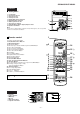
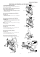
CD-M8000W/CP-M8000 NAMES OF PARTS CD-M8000W Front panel 1. Disc Tray 2. Timer Set Indicator 3. On/Stand-by Button 4. Tuner (Band) Button 5. CD Button 6. Headphone Socket 7. Microphone Level Control 8. Microphone Socket 9. Tape (1 2) Button 10. Video/Auxiliary Button 11. Equaliser Mode Select Button 12. Monster Bass/Demo Mode Button (with Indicator) 13. Disc Tray Open/Close Button 14. Disc Skip Button 15. Volume Control 16. Tape 1 Cassette Compartment 17. Tape 2 Cassette Compartment 18.
CD-M8000W/CP-M8000 CD-M8000W Rear panel 1. Cooling Fan 2. AC Voltage Selector 3. AC Power Lead 4. Transport Screw 5. FM 75 Ohms Aerial Terminal 6. FM Aerial Earth Terminal 7. AM Loop Aerial Socket 8. Span Selector Switch 9. Video/Auxiliary (Audio Signal) Input Sockets 10. Speaker Terminals 4 5 6 7 8 1 2 9 10 Note: This product is equipped with a cooling fan inside, which begins to run at a specified volume level for better heat radiation. Remote control 3 1 1. Remote Control Transmitter 2.
CD-M8000W/CP-M8000 DISASSEMBLY CD-M8000W Caution on Disassembly Follow the below-mentioned notes when disassembling the unit and reassembling it, to keep it safe and ensure excellent performance: 1. Take cassette tape and compact disc out of the unit. 2. Be sure to remove the power supply plug from the wall outlet before starting to disassemble the unit. 3. Take off nylon bands or wire holders where they need to be removed when disassembling the unit.
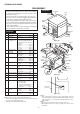
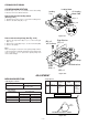
CD-M8000W/CP-M8000 Tape Mechanism (E2)x1 (E3)x1 Mic PWB (M2)x1 (E3)x1 (E3)x1 Turntable Power PWB Front Panel (G2)x1 Loading Tray Transformer PWB (M1)x2 Main PWB (G2)x1 Main PWB (E3)x1 Amp. PWB Figure 7-1 (F1)x4 ø3x6mm (F2)x1 CD Player Unit (F1)x1 ø3x10mm (F2)x3 Figure 7-4 Headphones PWB (N1)x3 Loading Tray (F4)x1 (F1)x1 ø3x10mm 3 Amp.
CD-M8000W/CP-M8000 CD Mechanism (Q1)x1 (Q2)x2 (Q1)x1 Loading Tray Figure 8-1 CP-M8000 STEP REMOVAL 1 Front Panel/ Supper Tweeter PROCEDURE 1. Net Ass'y ................ 2. Catching Holder ..... 3. Screw ..................... 4. Screw ..................... FIGURE (A1) x1 (A2) x4 (A3) x4 (A4) x2 8-2 8-3 2 Woofer 1. Screw ..................... (B1) x4 8-3 3 Tweeter 1. Screw ..................... (C1) x4 8-3 4 Midrange 1. Screw .....................
CD-M8000W/CP-M8000 REMOVING AND REINSTALLING THE MAIN PARTS TAPE 2 TAPE MECHANISM SECTION Clutch Ass'y Perform steps 1 to 7 and 10 of the disassembly method to remove the tape mechanism. Record/Playback Head How to remove the record/playback and erase heads (TAPE 2) (See Fig. 9-1) 1. When you remove the screws (A1) x 2 pcs., the record/ playback head and three-dimensional head of the erase head can be removed. Erase Head How to remove the playback head (TAPE 1) (See Fig. 9-2) (A1) x 2 Ø2 x 6mm 1.
CD-M8000W/CP-M8000 CD MECHANISM SECTION Loading Motor Perform steps 1, 2, 3, 12, 13, 14 and 15 of the disassembly method to remove the CD mechanism. CD Loading Motor PWB Loading Tray How to remove the loading motor (See Fig. 10-1) (A1) x 1 (A1) x 2 1. Bend the hooks (A1) x 5 pcs., to remove the loading motor. 2. Remove the drive belt (A2) x 1 pc. (A1) x 2 Loading Motor Pulley Drive Belt (A2) x 1 Figure 10-1 How to remove the pickup (See Fig. 10-2) Stop Washer (B3) x 2 (B1) x 1 ø2.6 x 6mm 1.
CD-M8000W/CP-M8000 TUNER SECTION CD SECTION fL: Low-range frequency fH: High-range frequency • AM IF/RF Signal generator: 400 Hz, 30%, AM modulated • Adjustment Since this CD system incorporates the following automatic adjustment functions, readjustment is not needed when replacing the pickup. Therefore, different PWBs and pickups can be combined freely. Each time a disc is changed, these adjustments are performed automatically. Therefore, playback of each disc can be performed under optimum conditions.
CD-M8000W/CP-M8000 TEST MODE • Setting the test mode Any one of test mode can be set by pressing several keys as follows. + + TEST:CD operation test Function:-CD test mode. -Enter test mode. C D T E S T IL isn't done OPEN/CLOSE operation is using manual. << >>, << >> buttons make pick's slide possible. <> key input. Do TOC IL.
CD-M8000W/CP-M8000 Standard Specification of Stereo System Error Message Display Contents Error Contents DISPLAY Notes TAPE Mechanism Error. 'ER-TA**' 00: Tape Mechanism Error. 01: Initial Error. 02: 03: CD Pickup Mechanism Error. 'ER-CD**' 01: PU-IN SW Detection NG. 02: 03: 04: CD Changer Mechanism Error. 'ER-CD**' (*) 10: Changer Error. 11: Initial Error. 12: 13: CD DSP Communication Error 'ER-CD**' 31: DSP COMMUNICATION ERROR Focus Not Match. 'NO DISC' IL Time Over. TUN PLL Unlock.
CD-M8000W/CP-M8000 NOTES ON SCHEMATIC DIAGRAM • The indicated voltage in each section is the one measured by Digital Multimeter between such a section and the chassis with no signal given. 1. In the tuner section, indicates AM indicates FM stereo 2. In the main section, a tape is being played back. 3. In the deck section, a tape is being played back. ( ) indicates the record state. 4. In the power section, a tape is being played back. 5. In the CD section, the CD is stopped.
CD-M8000W/CP-M8000 TO MAIN SECTION M TO DISPLAY SECTION CD RES CLAMP SW O/C DISC NO 2 3 4 5 6 7 8 9 10 CNP8 2 3 4 5 6 1 2 3 4 5 6 CNS4 CL 1 1 1 2 3 4 5 6 CNP4 DI 8 DO 7 CE 6 DRF 5 WRQ +6.
CD-M8000W/CP-M8000 +B +B6 IC301 TA7358AP FM FRONT END 9 8 5 6 L IN 31 R IN 32 VCC 23 VRK1 MIC VOLUME FM+B 2 3 VCO 16 FM/AM MO/ST FM MPXIN DET AM IF 18 L R 14 15 12 CE DI CLK DO IC302 LA1832S FM IF DET./ FM MPX./ AM IF 11 3 4 5 6 17 9 10 21 +B5 +B5 JK690 VIDEO/AUX L AUX R 8 17 L 9 R 16 TAPE L 10 R 15 L 11 TUNER R 14 CD L 12 R 13 CNS11 CNP7 FROM CD SECTION TAPE 1 L-CH P.B. HEAD R-CH 17 13 SWITCHING IC903 KIA4558P OPE AMP.
CD-M8000W/CP-M8000 FL701 FL DISPLAY +B5 1 13 14 ~ 19 27 ~ 32 33 ~ 41 5 ~ 12 351 1V TO CD SECTION 45 +B9 TAPE MECHANISM ASS'Y Q705 X351 6 kHz +B9 3 38 56 52 51 48 46 62 60 40 30 25 13 54 86 ~ RESET 91 IC701 IX0532AW SYSTEM MICROCOMPUTER VDD 92 93 100 1 2 4 5 6 7 8 9 1 0 11 12 31 37 29 26 15 41 16 1 7 20 21 22 23 24 +B9 XL700 4.194304 MHz +B9 TO CD SECTION RESET SW601 SPAN SELECTOR SP DET. Q709 +B7 +B9 FAN MOTOR DRIVER Q907 M M IC901 STK41217 POWER AMP.
CD-M8000W/CP-M8000 CD SERVO PWB-C A CD SIGNAL C34 C33 C32 PICKUP UNIT C30 C57 C28 PICKUP HPC1LX +B 80 79 78 77 76 75 74 73 1 2 3 4 5 6 7 8 9 C6 0.1 R12 C8 330 0.0027 +B C50 22P(CH) TP1 TP2 10 6 3 2 + R17 R18 + LD_M+ LD_M– + + +B C46 100/10 VCC4 M+ M– VCC3 SP- SP+ SPO VCC2 22 23 24 25 26 27 28 29 30 31 32 33 34 35 36 37 38 39 40 41 42 C41 100/10 +B +B G H • NOTES ON SCHEMATIC DIAGRAM can be found on page 14.
C37 0.1 C36 0.22/50 C35 0.047 4 LVSS 43 LCHO 42 LVDD 41 SBCK/FG DEFECT V/*P FSEQ MONI1 MONI2 MONI3 MONI4 MONI5 VSS VDD DOUT TEST 6 GPDAC CONT4 CONT5 N 18 ADAVDD 19 ADAVSS 20 TDO R16 1K 1K 1K 3 24 25 26 27 28 29 30 31 32 33 34 35 36 37 38 39 40 C14 100/10 9 R17 R18 C13 0.022 C22 0.01 CNP8 XL1 33.8688 MHz R43 220 +B ZD1 DZ3.3BSB +B C23 10/25 R24 2.2K +B R22 100 C16 330/6.3 R25 2.2K C26 0.0015 C25 R27 0.0015 10K +B C51 0.
CD-M8000W/CP-M8000 7 8 9 M_+13V +B –15V –B C617 2.2/50 6 C619 1/50 7 8 9 C625 1/50 + – RIN LSEL0 RSEL0 L4 R4 AUX DECK RTRE 17 C624 1/50 16 C628 1/50 R2 14 TUNER R1 L1 12 R624 13 CD C630 1/50 4.7K SP_RLY 11 SP_DET 12 SW+5V 13 –20dBAT IC851 KAI7812AP VOLTAGE REGULATOR +B C S_MUTE IC8 KIA45 OPE –B IC860 KIA4558P C867 1/50 7 4 1 R881 4.7K 1 R875 100K R867 100K C845 0.047 C863 22/50 100K R874 C864 22/50 +B A_+5V +B SW_5.
CD-M8000W/CP-M8000 MAIN PWB-A(1/2) 24 CLK VDD 23 +B VREF ROUT C602 22/25 C614 10/50 22 21 C610 0.22 20 19 RIN RSEL0 R4 +B R608 10K CD SIGNAL PLAYBACK SIGNAL VIDEO SIGNAL RECORD SIGNAL MIC SIGNAL R633 39K R606 3.9K C608 0.22 RBASS FM SIGNAL R631 8.2K C612 0.0015 RTRE R632 8.2K C620 1/50 18 L-CH C631 390P C632 390P JK601 VIDEO/AUX R634 39K R-CH C622 10/50 17 C624 1/50 16 C626 1/50 R3 15 C641 47P C628 1/50 R2 14 CHASSIS R618 4.7K R1 13 C630 1/50 R623 4.
CD-M8000W/CP-M8000 SPAN A LED B PWB-B4 +B 2 3 G08 G09 P01 P02 P03 P04 P05 P06 P07 P08 P09 P10 P11 P12 P13 P14 P16 P15 P17 41 40 39 38 37 36 35 34 33 32 31 30 29 28 27 19 18 17 16 15 14 13 12 Q705 KTC3199 GR R793 1K R796 680 G8 G9 S1 S2 S3 S4 77 S14 76 S15 R750 47K 75 S16 74 DIST4/S17 D702 DS1SS133 73 DIST3/S18 72 DIST2/S19 71 DIST1/S20 1 Q703 KRC102 M +10V S5 78 S13 3 2 S6 79 VLOAD 1 LED707 4204UYT7 80 S7 S12 1 Q702 LED708 4204UYT7 KRC102 M 2 3 R790 680
CD-M8000W/CP-M8000 DISPLAY PWB-B1 8 17 16 15 14 13 12 11 10 9 8 7 6 F G02 G01 G03 G04 G06 G05 G07 G08 G09 P01 P02 P03 P04 P05 SPAN 5 1 R795 1.5 C703 0.022 C702 220/10 C701 1/50 G1 G2 G3 G4 G5 G6 G7 G8 G9 S1 S2 S3 S4 S5 87 88 89 90 91 92 93 94 95 96 97 98 99 100 1 –20dBATT 2 +B VDD R763 1K R702 1K R703 1K R704 R705 1K 1K R706 1K R707 R708 1K 1K SUB-CE/DSA_STB 3 T-BIAS 4 T_T1/T2 5 REC/PLAY 6 CD RESOUT 7 WRQ 8 SPAN 9 RESET 10 XL701 4.
CD-M8000W/CP-M8000 7 6 5 4 2 1 3 R951 3.9K R936 56K R935 56K C962 0.22 C961 0.22 C940 220P R906 1K R909 56K R910 56K R911 100(1/4W) Fusible R967 22K(1/2W) C958 0.1/50 SPDET VH– R943 680(2W) 22K (1/2W) C901 3300/100 D901 DS1N404S ZD951 DZ130BSB C952 220/25 D D909 DS1SS133 R968 C902 3300/100 C918 0.22/50 C917 0.22/50 R966 22K (1/2W) C903 C904 4700/50 4700/50 Q909 KRA107 M 1 R952 3.
CD-M8000W/CP-M8000 AMP. PWB-H1 FM SIGNAL R923 56K L-CH L-CH LG901 C929 0.22 R925 10(1/2W) C927 0.22 RFM940 12(1W) C945 10/50 R946 47K L901 3.0µH CNP907 FAN MOTOR DRIVER R939 1K D912 DS1SS133 R941 560(2W) R942 560 (2W) R937 15K D915 DS1SS133 DFM922 DS1SS133 R938 68K D916 DS1SS133 C943 47/50 CNS907 2 2 1 1 2 2 M_+13V 1 FW901 FW901A D801 D10XB60F C811 0.22(ML) PT801 POWER TRANSFORMER C812 0.
CD-M8000W/CP-M8000 AM LOOP ANTENNA SO301 FM ANTENNA TERMINAL A 2 1 2 1 CNP301 R311 R314 22 C309 0.001 100K R313 33K 3 C305 4.7P (CH) C310 15P (CH) B 4 C323 0.022 5 +B 6 C312 0.022 +B R322 680 Q302 KTC3194 Y 7 T301 FM OSC. R325 47K OSC BUFF T302 C311 R302 10 18P C324 8.2P(UJ) FM IF C318 100P 1 2 CF303 FM SIGNAL R316 4.7K AM SIGNAL AM BAND COVERAGE fL 8 9 C306 0.022 C335 560P C334 22P (UJ) C307 10/16 VD303 KDV147B T303 R323 68K C313 22P R309 (CH) 10K 3 AM OSC.
CD-M8000W/CP-M8000 MIC PWB-G MIC SIGNAL CK7 0.47/50 CK8 4.7/50 CK9 2.2/50 RK48 10K CLOCK 41 RK10 1K 3 VACL LATCH 40 RK9 1K 4 MIC1 IN PS2 39 5 ALC1 PS1 38 6 MIC1NF IN VCF IL 37 7 MIC1 OUT L OUT 36 8 MIC1VOL IN R OUT 35 0.15 2.2/50 CK30 2.2/50 CK49 100P CK52 1/50 47P 2.2/50 VOL IN 30 CK24 2.2/50 5.6K CK25 CK12 MICOUT 2.2/50 14 LPF2OUT 29 15 LPF1 IN1 LPF2IN2 28 16 LPF2 IN2 LPF2IN1 27 6 RK43 18K 2.2/50 0.
CD-M8000W/CP-M8000 TO DISPLAY PWB P31 12 - D CNPK1 CNS602 1 2 3 4 5 6 7 8 9 10 11 R391 X351 C358 10 11 12 C611 C607 C62 C609 C625 R618 C623 C627 IC601 1 2 3 4 5 6 7 8 9 C641 R623 R617 C622 C628 C620 R620 C610 24 23 22 21 20 19 18 17 16 15 14 13 C630 C614 C608 C624 BI602 R627 R625 C606 R612 G C602 R606 C635 E C B R626 C374 C372 R608 R611 C618 B C E Q606 R614 R362 C368 R607 C636 R622 C616 R616 C631 R631 B C E C373 C626 R363 R615 C615 C617 E C B R361 C371 R35
CD-M8000W/CP-M8000 TO CD SERVO PWB P34 4 - A CNP701 CNP7 FROM TAPE 1 PLAYBACK HEAD P35 10 - F BK BL BL BK BK BL RD BK CNS11 1 2 3 4 5 6 7 8 21 Q122 R156 B C E C146 R140 R627 R625 C122 C116 R174 C118 R106 C154 R166 R167 E C B C152 Q128 R164 R162 BR Q124 C613 1 2 3 IC851 D859 C855 R605 C606 C853 IC852 IC853 C619 C607 C621 C609 C625 C858 R853 C843 D851 D858 C852 C857 C629 IC854 1 2 3 BROWN RD(R) RED OR ORANGE YL YELLOW GR GREEN BL BLUE VL VIOLET GY GR
CD-M8000W/CP-M8000 A LED B PWB-B4 RX701 REMOTE SENSOR 1 3 2 C701 R794 LED704 C716 C717 R795 B 5 6 7 8 9 10111213141516171819 1 R783 R707 C707 R793 R763 R792 Q705 B C E FL701 R702 D709 D710 R740 R760 R780 Q706 B C E CNP905 R775 C709 R776 C710 RD19 R778 SW723 DISC SKIP 4 E C B R722 SW715 TIMER/ SLEEP SW716 TUNING/ TIME UP R SW717 REC PAUSE RD20 Q707 E C B 1 3 5 7 9 CNP702 2 4 6 8 10 R772 C712 R773 C702 R739 R779 TO POWER PWB P33 8 - D Q708 G 1 10 FFC702 P35 8 -
CD-M8000W/CP-M8000 LED A PWB-B3 R771 LED703 LED701 RD01 45 85 75 R754 IC701 55 45 40 20 R731 35 25 XL701 C706 Q710 51 50 1 2 3 R757 5 10 15 1 R753 70 65 60 CNP701 R752 90 95 100 BI704 1 Q702 Q701 3 3 3 2 2 2 1 1 1 1 2 3 4 5 6 7 8 9 10 11 12 13 14 15 16 17 18 19 20 21 R732 RD16 RD17 R735 R734 R746 SW702 FAST REWIND/ PRESET DOWN R790 RD05 SW706 REVERSE PLAY RD02 RD06 SW707 REVERSE MODE SW705 PLAY DISPLAY PWB-B1 7 8 CNP601 R755 R796 LED707 SW704 STOP SW718 MEMORY/ SE
CD-M8000W/CP-M8000 M903 FAN MOTOR RD BR A CNS907 2 1 1 5 FW901 2 1 1 1 CNP705 5 5 4 3 2 1 1 1 2 CNS903 RD 1 WH FW901A 2 RD BI903 RFM940 JK701 HEADPHONES RD WH BI902 CNP907 FW901 B CNS902 2 R943 4 RD C952 5 WH 7 HEADPHONES PWB-B2 3 WH 6 BK 7 C918 R950 R949 C939 R909 R907 R910 R908 ZD951 C904 D913 DFM922 C C917 R905 D902 C915 R969 R965 C911 R906 C913 C905 C912 C940 R936 R935 R970 R942 9 8 7 6 5 4 3 2 1 R914 R915 R913 CNS901 FROM MAIN PWB P31 7-H
CD-M8000W/CP-M8000 P30 1 - F FROM DISPLAY PWB CNS705 R807 ZD804 CNP905 1 2 3 4 R806 R803 R810 R819 ZD801 R811 ZD802 Q803 C819 C823 B C E PT801 POWER TRANSFORMER R805 D809 R802 TRANSFORMER PWB-H3 D810 C824 C822 C821 C809 127 V 220 V 5 F804 T5A L 250V 6 127 V AC POWER SUPPLY CORD AC 110/127/220/ 230-240 V, 50/60 Hz K801 110 V C811 D801 C812 7 220 V 230-240 V F803 T5A L 250V 4 C810 3 CNP903 2 F805 T5A L 250V D802 1 230-240 V 110 V F801 T10A L 250V F806 T2A L 250V CNP
CD-M8000W/CP-M8000 P30 1 - E FROM DISPLAY PWB CNS701 P29 8 - A FROM MAIN PWB CNS11 12 CD SERVO PWB-C 11 A C5 C6 1 C50 R49 10 R4 R6 C53 C39 COLOR TABLE R47 C46 CNP4 6 5 4 3 2 1 CNP3 6 5 4 3 2 1 5 BROWN RD(R) RED OR ORANGE YL YELLOW GR GREEN BL BLUE VL VIOLET GY GRAY WH(W) WHITE BK BLACK PK PINK CNS3A PICKUP UNIT(306) 654 321 CD MOTOR PWB-D 654 321 CNS3B RD WH GY WH GY WH GY WH 7 8 1 654 321 CNP3A 1 1 2 3 4 5 6 7 8 CNS2B SW4 PICKUP IN + CNS2A CNS1B 1 2 3 4 5
CD-M8000W/CP-M8000 TAPE MECHANISM ASSEMBLY P30 3 - H TO DISPLAY PWB CNP702 FFC702 10 1 TAPE MECHANISM PWB-F SW 1 3 5 79 2 4 6 8 10 SW SW PH 1 2 SOLENOID + - SOLENOID TAPE MOTOR TAPE 1 PLAYBACK HEAD CD LOADING MOTOR PWB-E PK WH BK TAPE 2 RECORD/PLAYBACK/ERASE HEAD SW1 OPEN/CLOSE + WH BK PK GR M3 T/T UP/DOWN LOADING MOTOR 123456 3 2 1 CNS102 P29 11 - D FROM MAIN PWB – CNP101 P29 9 - A TO MAIN PWB 1 CNS4 RD WH BK WH BK WH SW2 CLAMP BI4 1 2 3 4 5 6 6 SW3 DISC NUMBER 7 8
CD-M8000W/CP-M8000 VOLTAGE IC101 IC302 IC601 PIN VOLTAGE NO. 1 0V 0V 2 3 0.5 V PIN VOLTAGE NO. 1 2.4 V 0V 2 3 0V 0V 4 2.9 V 5 4.8 V 6 0.1 V 7 4.2 V 8 3.3 V 9 10 0 V 11 5.1 V 12 2.2 V 13 5 V 14 0 V 15 0 V 16 2.3 V 17 5 V 18 0.6 V 19 0.8 V PIN VOLTAGE NO. 1 0V 0V 2 3 0V 5.3 V 4 5.3 V 5 5V 6 5V 7 5.3 V 8 5V 9 10 5 V 11 5 V 12 5 V 13 5 V 14 5 V 15 5 V 16 5 V 17 5 V 18 5 V 19 5 V 20 5 V 21 5 V 22 5 V 23 10.2 V 24 0 V 4 5 6 7 8 9 10 11 12 13 14 15 16 17 18 19 20 21 22 23 24 2V 0V 1.3 V 0V 0.6 V 3.5 V 3.
CD-M8000W/CP-M8000 WAVEFORMS OF CD CIRCUIT Stopped CH1=500 mV DC 10:1 CH3=500 mV DC 10:1 T 1 IC1 21 Stopped CH1=200 mV DC 10:1 500 ms/div (500 ms/div) NORM:20 kS/s T 1999/04/07 09:51:15 500 ms/div (500 ms/div) NORM:20 kS/s CH2=500 mV DC 10:1 FDO 1 T FDO 1 IC1 21 2 6 IC1 22 1 TDO 2 IC1 20 3 SPDO CH1 v/DIV 500 mV =Filter= Smoothing : ON BW : FULL =Offset= CH1 : 0.000 V CH2 : 0.0 V CH3 : 0.000 V CH4 : 0.
CD-M8000W/CP-M8000 TROUBLESHOOTING When the CD does not function When the CD section does not operate when the objective lens of the optical pickup is dirty, this section may not operate. Clean the objective lens, and check the playback operation. When this section does not operate even after the above step is taken, check the following items. Remove the cabinet and follow the trouble shooting instructions.
CD-M8000W/CP-M8000 Stopped CH1=500 mV DC 10:1 (1) Focus-HF system check. Although a CD is inserted and the cover is closed, "NO DISC" is displayed. CH3=500 mV DC 10:1 T 500 ms/div (500 ms/div) NORM:20 kS/s FDO 1 Press the OPEN/CLOSE switch (SW1) without inserting a disc, and try starting the playback operation. TDO 3 CH1 v/DIV 500 mV =Filter= Smoothing : ON BW : FULL =Offset= CH1 : 0.000 V CH2 : 0.0 V CH3 : 0.000 V CH4 : 0.
CD-M8000W/CP-M8000 (2) Tracking system check. Check the TE waveform at pin 15 on IC1. If the waveform shown in Figure 40-1 appears and soon after NO DISC appears ? Yes The tracking servo is not activated. Check the peripheral circuits at pins 14, 15 and 20 on IC1, and CNS1A/B. Yes A normal jump operation cannot be completed or the beginning of the track cannot be found. Check the around pin 20 on IC1. No "Initialization" is possible, but play is not possible ? No "Initialization" is not possible.
CD-M8000W/CP-M8000 (4) PLL system check. Stopped CH1=500 mV DC 10:1 When a disc is loaded, start play operation. CH3=1 V DC 10:1 1999/04/05 17:33:17 CH4=1 V 500 ms/div (500 ms/div) DC 10:1 NORM:20 kS/s PDO1 3 4 The HF waveform is normal, but the TOC data cannot be read. PDO2 T FDO 1 Check the PDO waveform. (Figure 41-1) CH1 v/DIV 500 mV =Filter= Smoothing : ON BW : FULL =Offset= CH1 : 0.000 V CH2 : 0.0 V CH3 : 0.00 V CH4 : 0.
CD-M8000W/CP-M8000 FUNCTION TABLE OF IC IC1 VHiLC78645NE1: CD Servo (LC78645NE) (1/2) Pin No. Terminal Name Input/Output Setting in Reset 1 SLCO Output — 2 SLCIST Input — 3 EFMIN Input — 4 RF Output — 5 RFVDD Input — RF power terminal. 6 RFVSS — — RF earth terminal. To be connected to 0 V. 7 FIN1 Input — A+C signal input terminal. 8 FIN2 Input — B+D signal input terminal. 9 TIN1 Input — E signal input terminal. 10 TIN2 Input — F signal input terminal.
CD-M8000W/CP-M8000 IC1 VHiLC78645NE1: CD Servo (LC78645NE) (2/2) Pin No. Terminal Name Input/Output Setting in Reset 44 RVSS — — 45 RCHO Output LVDD /2 46 RVDD Input — 47 XVDD Input — 48 XOUT Output — 49 XIN Input — 50 FSX/16MIN Input/Output Input 51 XVSS — — 52* C2F Output H C2 FLAG monitor port. 53* EFLG Output L C1, C2 error corrected monitor port.
CD-M8000W/CP-M8000 LDD LDS FR VVDD PCKIST VVSS PD02 PD01 CONT1 CONT2 CONT3 VSS VDD5 DRF *RES *WRQ DO DI CL CE IC1 VHiLC78645NE1: CD Servo (LC78645NE) 80 79 78 77 76 75 74 73 72 71 70 69 68 67 66 65 64 63 62 61 SLCO 1 60 DATA SLCIST 2 59 BCK EFMIN 3 58 LRCK RF 4 57 ASDFIN RFVDD 5 56 ASDACK RFVSS 6 55 ASLRCK FIN1 7 54 16MOUT FIN2 8 53 EFLG TIN1 9 52 C2F TIN2 10 51 XVSS LC78645NE VREF 11 50 FSX/16MIN REF1 12 49 XIN 35 36 37 FIN1 + – FIN
CD-M8000W/CP-M8000 DI CLK VDD VREF 2 1 24 23 22 CCB INTERFACE LTRE 6 20 RBASS CONTROL CIRCUIT CONTROL CIRCUIT LBASS 5 21 ROUT CONTROL CIRCUIT LOUT 4 RVref CE 3 LVref VSS IC601 VHiLC75341/-1: Audio Processor (LC75341) 19 RTRE 18 RIN LIN 7 LSEL0 8 L2 L1 R1 R2 R3 R4 RTRB R2 L3 R3 L4 R4 16 RSEL0 15 RIN 14 RBASS 13 ROUT 12 VREF 11 VDD 10 CLK 9 R1 Video Tape Tuner 24 23 22 21 20 19 18 17 16 15 14 13 VSS LOUT LBASS 7 8 9 10 11 12 Figure 45 BLOCK DIA
CD-M8000W/CP-M8000 IC701 RH-iX0532AWZZ: System Microcomputer (IX0532AW) (1/2) Pin No. 1 Port Name VDD Terminal Name VDD Input/Output Input Function (+) Power supply. 2 P37 -20dBATT Output -20dB Attenuator. 3* P36 SUB_CE Output MP3 sub microcomputer. 4 P35 T_BIAS Output Tape record bias. 5 P34 T_T1/T2 Output Tape T1/T2 change. 6 P33 T_REC/PLY Output Tape REC/PLAY change. 7 P32 CD_RESOUT Output CD DSP reset. 8 P31 CD WRQ Input CD write read request..
CD-M8000W/CP-M8000 IC701 RH-iX0532AWZZ: System Microcomputer (IX0532AW) (2/2) Pin No. Port Name Terminal Name Input/Output Input Function 54 P120 O/C SW 55 P117 MIC SW 56 P116 KARA_LATCH Output Karaoke latch. 57* P115 NO USE Output Open 58* P114 MPEG POWER Output MPEG power control. 59* P113 NO USE Output Open 60 P112 NO USE Input Open Input CD OPEN/CLOSE SW. Mic switch input.
CD-M8000W/CP-M8000 ICK1 VHiM65856SP-1: Mic Amp. (M65856SP) (1/2) Pin No. Port Name Input/Output Input Function 1 MIC SW 2 MCLKCONT — Clock Control. Controls built-in clock generation circuit with external R. 3 VALC — ALC operating voltage setting terminal. To set ALC operating voltage according to applied voltage. 4 MIC1 IN 5* ALC1 6* MIC1NFIN Input 7* MIC1 OUT Output 8 MIC1 VOLIN Input Microphone 1 volume input.
CD-M8000W/CP-M8000 ICK1 VHiM65856SP-1: Mic Amp. (M65856SP) (2/2) Pin No. Port Name Input/Output Input Function Monaural input for external KEYCONTROL IC. Input/Output interface terminal for external KEYCONTROL IC. 33* KEYCONIN 34* SOURCEOUT 35 R OUT Output Rch mixing output. 36 L OUT Output Lch mixing output. 37 VCF IL — 38* PS1 Input Phase shift input 1. Determines a constant at time of phase shift. 39* PS2 Input Phase shift input 2. Determines a constant at time of phase shift.
CD-M8000W/CP-M8000 FL DISPLAY FL701 VVKNA09SS29-1 GRID ASSIGNMENT 2G 3G X-BASS 4G MP3 5G 1 6G 3 2 8G 7G 9G REC ST SLEEP RDS EON kHz TP TI PTYIPTY MHz TA MEMORY col S2 1G S1 S3 S4 a h j k f b g m e c p r n Dp d (1G~8G) ANODE CONNECTION 1G P1 P2 P3 P4 P5 P6 P7 P8 P9 P10 P11 P12 P13 P14 P15 P16 P17 P18 P19 P20 P21 2G 3G X-BASS MP3 4G 5G 6G 2 3 col 1 7G 8G S1 S2 S3 S4 a S1 S2 S3 S4 a S1 S2 S3 S4 a S1 S2 S3 S4 a S1 S2 S3 S4 a S1 S2 S3 S4 a S1 S2 S3 S4 a S1 S2
CD-M8000W/CP-M8000 PARTS GUIDE MINI COMPONENT SYSTEM MODEL CD-M8000W SPEAKER SYSTEM MODEL CP-M8000 “HOW TO ORDER REPLACEMENT PARTS” To have your order filled promptly and correctly, please furnish the following information. 1. MODEL NUMBER 2. REF. No. 3. PART NO. 4. DESCRIPTION For U.S.A. only Contact your nearest SHARP Parts Distributor to order.
CD-M8000W/CP-M8000 NO.
CD-M8000W/CP-M8000 NO.
CD-M8000W/CP-M8000 NO.
CD-M8000W/CP-M8000 NO.
CD-M8000W/CP-M8000 NO.
CD-M8000W/CP-M8000 NO.
CD-M8000W/CP-M8000 CD-M8000W 701 306 A 304 306-2 701 306-1 B 704 306-3 302 C 301 702 303 D 703x2 E M1 F 305 M2 305x2 G SW4 PWB-D H 1 2 3 4 Figure 7 CD MECHANISM EXPLODED VIEW –7– 5 6
CD-M8000W/CP-M8000 CD-M8000W 604 273 202-1 604 202 616x3 IC853 PWB-A IC852 604 IC851 A 604x2 BELT CONNECTION FF/REW Tape FF/REW ROLLER Motor ROLLER ASS'Y ASS'Y FLYWHEEL FLYWHEEL ASS'Y MAIN BELT ASS'Y TAPE2 TAPE1 604 Silicon Grease 610x5 207 614x12 614 267 614x2 268 244 B 202-2 230 611x2 603 264 271 268 208 272 PWB-F 227 255 PWB-B3 614x3 266 209 257 272x2 PWB-B4 258 M904 C PWB-B4 608x15 256 254 PWB-B1 208-1,208-2, 208-3,208-4, 208-5,208-6, 208-7,208-8, 208-9,208-10, 208-
CD-M8000W/CP-M8000 CD-M8000W 217 609x2 A 205 249 243 215 B 241 CD MECHANISM C 216 609x2 265 SW3 PWB-E SW2 SW1 D 235 251 225 226 M3 224 251 M3 240 232 E 204 601 251 214 251 F 223 251 619x2 238 221 239 PWB-C G 233 613 229 222 236 237 206 236 218 620 H 620 1 2 3 4 Figure 9 CABINET EXPLODED VIEW (2/2) –9– 5 6
CD-M8000W/CP-M8000 CP-M8000 916x2 916x2 (with Capacitor C1, C2, C3, C4) A 906 901 907 917x2 SP7 SP8 913x4 B 908 914x4 910 917x2 920x3 919x4 C 902 912x2 909 903 905 D 904 911 SP1 SP2 E 915x4 918x4 SP5 SP6 F SP1 SP2 WOOFER 918x4 SP3 SP4 MIDRANGE SP5 SP6 TWEETER G BL BK BL BL BK BK SP7 SP8 SUPER TWEETER SP7 SP8 SUPER TWEETER BK BL SP5 SP6 TWEETER C1 C2 Capacitor (N.P.) 1.2 µF,250 V C3 C4 Capacitor (N.P.) 6.8 µF,250 V BK BK H BK 912x2 SP3 SP4 C1 C2 Capacitor (N.P.
CD-M8000W/CP-M8000 –– MEMO –– – 11 –
CD-M8000W/CP-M8000 –– MEMO –– – 12 –
CD-M8000W/CP-M8000 COPYRIGHT © 2002 BY SHARP CORPORATION ALL RIGHTS RESERVED. No part of this publication may be reproduced, stored in a retrieval system, or transmitted in any form or by any means, electronic, mechanical, photocopying, recording, or otherwise, without prior written permission of the publisher.