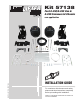
LoadLIFTER 5000 Kit 57138 Ford E-250/E-350 Van & E-350 Commercial Chassis MN-748 • (021210) • ECR 7428 rear application INSTALLATION GUIDE For maximum effectiveness and safety, please read these instructions completely before proceeding with installation. Failure to read these instructions can result in an incorrect installation.
TABLE OF CONTENTS Introduction . . . . . . . . . . . . . . . . . . . . . . . . . . . . . . . . . . . . . . . 2 Important Safety Notice . . . . . . . . . . . . . . . . . . . . . . . . . . . . . . . . . . . . . . . . . . . . . 2 Notation Explanation . . . . . . . . . . . . . . . . . . . . . . . . . . . . . . . . . . . . . . . . . . . . . . . . 2 Kit Hardware and Tools . . . . . . . . . . . . . . . . . . . . . . . . . . . . . 3 Installing the LoadLifter 5000 System . . . . . . . . . . . . . . . . . .
LoadLifter 5000 Introduction The purpose of this publication is to assist with the installation, maintenance and troubleshooting of the LoadLifter 5000 air spring kit. LoadLifter 5000 utilizes sturdy, reinforced, commercial grade single or double, depending on the kit, convolute bellows. The bellows are manufactured like a tire with layers of rubber and cords that control growth. LoadLifter 5000 kits are recommended for most 3/4 and 1 ton pickups and SUVs with leaf springs and provide up to 5,000 lbs.
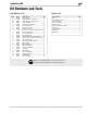
LoadLifter 5000 Kit Hardware and Tools TOOLS LIST HARDWARE LIST Item A B1 B2 C D E F G H I J K L M N O P Q R S T U V W X Y Part # 58736 07463 07464 03982 21837 34365 10785 01775 17103 18438 18435 18444 17405 17203 18427 11042 17444 18501 18489 20086 10466 21230 18405 21234 18401 21233 Description ............................... Qty Air Springs ..........................................2 Upper Bracket - Left Hand ..................1 Upper Bracket - Right Hand ................1 Lower Bracket ...........
LoadLifter 5000 Installing the LoadLifter5000 System CAUTION DANGER YOUR VEHICLE MAY BE EQUIPPED WITH A REAR BRAKE PROPORTIONING VALVE. ANY TYPE OF LOAD ASSIST PRODUCT COULD AFFECT BRAKE PERFORMANCE. WE RECOMMEND THAT YOU CHECK WITH YOUR DEALER BEFORE INSTALLING THIS TYPE OF PRODUCT. IF YOUR VEHICLE DOES NOT HAVE A REAR BRAKE PROPORTIONING VALVE OR IS EQUIPPED WITH AN ANTI-LOCK TYPE BRAKE SYSTEM, INSTALLATION OF A LOAD ASSIST PRODUCT WILL HAVE NO EFFECT ON BRAKE SYSTEM PERFORMANCE.
LoadLifter 5000 Forward Short Threads into the Air Spring Driver Side Passenger Side fig. 2 NOTE fig. 3 Finger tight only. Do not over tighten. 4. LOOSELY install the 3/8” lock washer (N) and 3/8 x 7/8” hex head cap screws (M). Leave loose to allow installation of the upper bracket. 5. Attach the lower bracket (C) to the bottom of the air spring. Use the forward, inboard hole as shown in fig. 4. Use this hole Driver Forward Use this hole fig. 4 Passenger 6.
LoadLifter 5000 LOWERING THE SUSPENSION NOTE It will be necessary to lower the suspension of the vehicle in order to provide clearance to install the air spring unit (fig. 6). The following are tips on lowering the axle or raising the frame. Please review them and determine how to proceed: fig. 6 1. If the vehicle is raised with an axle contact hoist, place axle stands under the frame and lower the axle as needed. 2.
LoadLifter 5000 3. Secure the stud using flat washer (K) and 3/8” lock nut (J). See fig. 9. Torque stud nut to 16ft-lbs. Outboard fig. 9 4. Tighten the hex head bolt securely to 16 ft–lbs. 5. LATE MODELS have an existing hole that lines up with the top hole in the bracket so it will not be necessary to drill on these models. On some models the existing hole may have a plastic stud for a wiring harness hanger protruding through it.
LoadLifter 5000 ATTACHING THE LOWER BRACKET NOTE Most late model vehicles have a small brake line hanger on the passenger side shock bracket that is welded to the axle (fig.12). Remove the bolt holding the wire brake line bracket to the shock mount. Move line aside and attach the brake line bracket spacer (O) to the axle using the existing M8 bolt removed. Attach the stock brake line bracket to the brake line bracket spacer with the M8 bolt (P), washer (Q) and nut (R) provided. Tighten both securely (fig.
LoadLifter 5000 fig. 15 Axle Vent Tube Bolt Rotate Counter Clockwise NOTE fig. 16 Some late models are equipped with the RSC (roll stability control) system (fig. 16). On these models it will be necessary to loosen the axle vent tube bolt and rotate the brake line junction box counter clockwise as far as it will let you. Tighten the axle vent tube bolt securely (fig. 17). 3. Secure the lower bracket to the axle using the saddle clamps (G), flat washers (K) and 3/8” nuts (J). See fig. 18. 4.
LoadLifter 5000 INSTALLING THE AIR LINES 1. Choose a convenient location for mounting the inflation valves. Popular locations for the inflation valve are: a. The wheel well flanges b. The license plate recess in bumper c. Under the gas cap access door d. Through the license plate NOTE Whatever the chosen location, make sure there is enough clearance around the inflation valves for an air chuck. 2. Drill two 5/16” holes to install the inflation valves. 3. Cut the air line assembly in two equal lengths.
LoadLifter 5000 Option 1 Option 2 fig. 21 7. Cut off the air line, leaving approximately 12” of extra air line. A clean square cut will ensure against leaks. Insert the air line into the air fitting. This is a push-to-connect fitting. Simply push the air line into the 90° swivel fitting (D) until it bottoms out (9/16” of air line should be in the fitting). 8. Install the minimum/maximum air pressure decal in a highly visible location.
LoadLifter 5000 2. If there is a problem with the inflation valve: a. Check the valve core by tightening it with a valve core tool. b. Check the air line by removing the air line from the barbed type fitting. Cut the air line off a few inches in front of the fitting and use a pair of pliers or vice grips to pull/ twist the air line off of the fitting. CAUTION DO NOT CUT OFF THE AIR LINE COMPLETELY AS THIS WILL USUALLY NICK THE BARB AND RENDER THE FITTING USELESS. 3.
LoadLifter 5000 Product Use, Maintenance and Servicing Suggested Driving Pressure Maximum Air Pressure 5 PSI 100 PSI FAILURE TO MAINTAIN CORRECT MINIMUM PRESSURE (OR PRESSURE PROPORTIONAL TO LOAD), BOTTOMING OUT, OVER-EXTENSION OR RUBBING AGAINST ANOTHER COMPONENT WILL VOID THE WARRANTY. MAINTENANCE GUIDELINES NOTE By following the steps below, vehicle owners will obtain the longest life and best results from their air springs. 1. Check the air pressure weekly. 2. Always maintain normal ride height.
LoadLifter 5000 Troubleshooting Guide 1. Leak test the air line connections, the threaded connection into the air spring, and all fittings in the control system. 2. Inspect the air lines to be sure none are pinched. Tie straps may be too tight. Loosen or replace the strap and replace leaking components. 3. Inspect the air line for holes and cracks. Replace as needed. 4. Look for a kink or fold in the air line. Reroute as needed.
LoadLifter 5000 fig. 23 Bad headlight aim Rough ride fig. 24 fig. 25 Sway and body roll Guidelines for Adding Air 1. Start with the vehicle level or slightly above. 2. When in doubt, always add air. 3. For motorhomes, start with 50-100 PSI in the rear because it can be safely assumed that it is heavily loaded. 4. If the front of the vehicle dives while braking, increase the pressure in the front air bags, if equipped. 5.
LoadLifter 5000 Warranty and Returns Policy Air Lift Company warrants its products, for the time periods listed below, to the original retail purchaser against manufacturing defects when used on catalog-listed applications on cars, vans, light trucks and motorhomes under normal operating conditions for as long as Air Lift manufactures the product.
LoadLifter 5000 Replacement Information If you need replacement parts, contact the local dealer or call Air Lift customer service at (800) 248-0892. Most parts are immediately available and can be shipped the same day. Contact Air Lift Company customer service at (800) 248-0892, first if: • Parts are missing from the kit. • Need technical assistance on installation or operation. • Broken or defective parts in the kit. • Wrong parts in the kit. • Have a warranty claim or question.
Need Help? Contact our customer service department by calling (800) 248-0892, Monday through Friday, 8 a.m. to 8 p.m. Eastern Time. For calls from outside the USA or Canada, our local number is (517) 322-2144. Register your warranty online at www.airliftcompany.