CD-ES700/CD-ES77 SERVICE MANUAL No. S5428CDES700/ MINI COMPONENT SYSTEM MODEL CD-ES700 CD-ES700 Mini Component System consisting of CD-ES700 (main unit) and CP-ES700 (speaker system). MODEL CD-ES77 CD-ES77 Mini Component System consisting of CD-ES77 (main unit) and CP-ES77 (speaker system). In the interests of user-safety the set should be restored to its original condition and only parts identical to those specified be used. CONTENTS CHAPTER 1. GENERAL DESCRIPTION [1] Specifications ..............
CD-ES700/CD-ES77 IMPORTANT SERVICE NOTES BEFORE RETURNING THE AUDIO PRODUCT BEFORE RETURNING THE AUDIO PRODUCT (Fire & Shock Hazard) Before returning the audio product to the user, perform the following safety checks. 1. Inspect all lead dress to make certain that leads are not pinched or that hardware is not lodged between the chassis and other metal parts in the audio product. 2.
CD-ES700/CD-ES77 Service E Market CD-ES700/CD-ES77 Manual 1. GENERAL DESCRIPTION CHAPTER [1] Specifications FOR A COMPLETE DESCRIPTION OF THE OPERATION OF THIS UNIT, PLEASE REFER TO THE OPERATION MANUAL. CD-ES700/CD-ES77 Tuner General Power source Power consumption Dimensions Weight AC 120 V, 60 Hz 135 W Width: 10-1/4" (260 mm) Height: 13" (330 mm) Depth: 12-7/8" (326 mm) 18.5 lbs. (8.
CD-ES700/CD-ES77 [2] Names of parts CD-ES700/CD-ES77 Front panel 1. Disc Trays 2. Timer Indicator 3. Power On/Stand-by Button 4. CD Track Up or Fast Forward, Tape 2 Fast Forward, Tuner Preset Up, Time Up Button 5. Clock/Timer Button 6. Tuning Up Button 7. Tuning Down Button 8. CD Track Down or Fast Reverse, Tape 2 Rewind, Tuner Preset Down, Time Down Button 9. Equalizer Mode Select Button 10. Tape 1 Cassette Compartment 11. Headphone Jack 12. Game/Video Input Jacks 13. Disc Number Select Buttons 14.
CD-ES700/CD-ES77 Remote control 1 1. Remote Control Transmitter 2. Disc Number Select Buttons 3. Disc Direct Search Buttons 4. CD Clear/Dimmer Button 5. Memory/Set Button 6. CD Track Down or Fast Reverse, Tape 2 Rewind, Tuner Preset Down, Time Down Button 7. CD Pause Button 8. Tape 2 Record Pause Button 9. Tuner (Band) Button 10. CD Button 11. Tape (1 2) Button 12. Game/Video Button 13. Power On/Stand-by Button 14. Clock/Timer Button 15. CD Random Button 16.
CD-ES700/CD-ES77 Service E Market CD-ES700/CD-ES77 Manual 2. ADJUSTMENTS CHAPTER • Signal generator: 1 kHz, 40 kHz dev., FM modulated [1] Mechanism section • • FM Band Coverage FM RF Specified Value Tape 1: Over 80 g Tape 2: Over 80 g Frequency Frequency Display — 87.50 MHz 98.00 MHz (10-30 dB) 98.00 MHz Setting/ Adjusting Point T301 (fL): 1.3 V ± 0.1 V L312 *1. Input: Antenna *2. Input: Antenna Specified Value Tape 1 Tape 2 30 to 80 g.cm 30 to 80 g.cm — 70 to 180 g.cm — 70 to 180 g.
CD-ES700/CD-ES77 [3] TEST MODE • Setting the test mode During stand-by mode, press ON/STAND-BY button while pressing down the button and X-BASS/DEMO button. then, press the CD button to enter the test mode. C D T E S T IL isn’t done OPEN/CLOSE operation is using manual. << >>,<< >>buttons make pick's slide possible. A IL isn’t done IL isn’t done to page 2-3 <> key input. Do TOC IL. Do normal play. When these following key is input into PLAY key, track number can be appoint directly.
CD-ES700/CD-ES77 A <> key input. Laser ON. <> key input. Tracking OFF play at that specific point. <> key input. Tracking ON play from that specific point. <> key input. Adjustment result automatically will display as below for each 2 sec : a) "FOF_XXXX" b) "TOF_XXXX" c) "TBAL_XX" d) "TGAN_XX" f) "FGAN_XX" g) "RFLS_XX" <> key input. STOP Sliding the PICKUP with<< in STOP mode.
CD-ES700/CD-ES77 [4] CD section CD Error code description Error 01 10* 11* 20* 21* 31 * Explanation When Pickup set inner position, inner switch cannot detect 'ON' level for 10 secs. CAM error. Can't detect CAM switch when CAM is moving. When it detect cam operation error during initialize process. TRAY error. Can't detect TRAY switch when TRAY is moving. When it detect TRAY operation error during initialize process. When it change to CD function, DSP cannot read initial data.
CD-ES700/CD-ES77 [5] CD Changer mechanism section • A number in the drawing sheet is the number of the parts guide (CHANGER MECHANISM PARTS).
CD-ES700/CD-ES77 2 139 APPLY SANKOL BEFORE FIX FIX ITEM 1 ACCORDING TO THE SHOWN PICTURE ABOVE ROTATE MODE BIG GEAR UNTIL REACH AS SHOWN IN PICTURE 2–6
CD-ES700/CD-ES77 3 143 APPLY GREASE 112 PULL THE LEVER UNITIL REACH THE ARROW MARK 2–7
CD-ES700/CD-ES77 4 FIGURE 2 FIGURE 1 152 118 142 APPLY GREASE SLOT CLAMP SW ARM INSIDE BASE SLOT 2–8
CD-ES700/CD-ES77 5 APPLY GREASE AT BOTTOM SIDE OF GEAR FOLLOW MARKING NO NEED APPLY GREASE AT BOTTOM SIDE APPLY GREASE AT TOP SIDE OF GEAR FOLLOW MARKING 127 OTHER THAN FIGURE 1 DIRECTION ALL N.G O.K 128 N.
CD-ES700/CD-ES77 6 APPLY GREASE AT HALF GEAR AREA ROTATE CLOCKWISE UNTIL REACH HERE (MAXIMUM) 129 2 – 10
CD-ES700/CD-ES77 7 CHANGE COLOR TO BLACK 148 151 150 2 – 11
CD-ES700/CD-ES77 8 TRAY BIG GEAR CHANGE COLOR TO BLACK MUST FREE FROM GREASE THE SHOWN AREA O.K GREASE APPLICATION LENGTH GREASE APPLICATION PORTION N.
CD-ES700/CD-ES77 9 APPLY GREASE AT BOTTOM SIDE ONLY 138 126 TR-RE JOINT GEAR C 125 APPLY GREASE ONLY AT TOP SIDE GEAR MUST FIX ACCORDING TO THE HOLE'S 2 – 13
CD-ES700/CD-ES77 10 148 147 146 145 2 – 14
CD-ES700/CD-ES77 11 121 APPLY GREASE 144 130 WHEN FIXING ITEM 2 MUST FOLLOW AS SHOWN 2 – 15
CD-ES700/CD-ES77 12 117 FIGURE 1 FIGURE 2 APPLY GREASE FIGURE 3 2 – 16 APPLY GREASE SC141
CD-ES700/CD-ES77 13 ITEM 2 , 3 MUST APPLY GREASE ON TOP SIDE GEAR ONLY 134 133 GEAR 112 O.K GEAR 112 N.G 132 TOP VIEW AFTER ASSY 2 – 17 FIX REVERSE N.
CD-ES700/CD-ES77 14 APPLY GREASE BEFORE FIX MOVE 112 UNTIL TOUCH THE WALL B A DURING GEAR A ROTATE MUST PRESS SHOWN AREA AND LEVER B WILL MOVE ARROW DIRECTION THEN FIX PART 108 SCREW TORQUE 2 108 +0.
CD-ES700/CD-ES77 15 APPLY GREASE 115 BEHIND THE LEVER NEED TO APPLY GREASE PULL IT THEN LEVER WILL MOVE IN 2 – 19
CD-ES700/CD-ES77 16 123 115 APPLY GREASE APPLY GREASE BEFORE FIX APPLY GREASE AT BOSS SPRING MUST ARRANGE UNDER THE HOOK O.K LR JOINT LEV BOARD R BOARD R LR JOINT LEV N.
CD-ES700/CD-ES77 17 ASSY REVERSELY N.
CD-ES700/CD-ES77 18 ASSY REVERSELY N.
CD-ES700/CD-ES77 19 AFTER FIX OUTER UP/DOWN LEVER HOLD SHOWN PORTION AND MOVE UP/DOWN THEN CONFIRM LEVER GO INSIDE THE HOLE OR NOT 120 IF GO INSIDE HOLE IS O.K BIGGER SLOT FACING OUT IF NO GO INSIDE HOLE IS N.
CD-ES700/CD-ES77 20 BIG SLOT FACING OUT 110 2 – 24
CD-ES700/CD-ES77 21 PUSH THE LEVER ACCORDING TO ARROW DIRECTION THEN FIX WHEN FIX MAIN BASE ASSY FOLLOW ACCORDING TO O.K PICTURE O.K MAKE SURE MECHA HOLDER SHAFT FIX PROPELY TO LEVER 2 – 25 N.G N.
CD-ES700/CD-ES77 22 APPLY SANKOL APPLY SANKOL ON TOP 101 APPLY SANKOL INSIDE THE SLOT & OTHER SHOWN PORTION RIB 102 RIB APPLY SANKOL AT TRAY SLIDING PORTION FIX TRAY NO 1 FIRST THAN FOLLOW OTHER 2 – 26 COSMO GUIDE TRAY HAVE MARKING AS SHOWN
CD-ES700/CD-ES77 23 111 GEAR UP/DOWN BOARD APPLY GREASE AT INNER & OUTER GEAR SLIDING PORTION WHEN FIX GEAR UP/ DOWN BOARD THE TWO LEVER MUST AT PARALLEL LINE & POSITION AT TOP MAX SIDE AFTER ASSY GEAR UP/DOWN BOARD 2 – 27
CD-ES700/CD-ES77 24 SCREW TORQUE 3 +0.
CD-ES700/CD-ES77 25 AFTER ASSY TOP PLATE FIX THE FFC FFC4 AFTER PUSH MAKE SURE SNAP PROPELY PRESS IN BACK PORTION 122 AFTER FIX PUSH FOLLOW ARROW DIRECTION 107 BEFORE LOCK SLOT IN AFTER LOCK BEFORE LOCK MUST CONFIRM AFTER LOCK BEFORE LOCK AFTER LOCK MUST CONFIRM 2 – 29
CD-ES700/CD-ES77 26 CAUTION O.K 1. MAKE SURE NO PWB CHIP INSIDE SET .( BEFORE FIX MAKE SURE PWB NO DUST , GREASE & ETC ) N.
CD-ES700/CD-ES77 27 THE TWO SLOT MUST FREE FROM GREASE APPLY GREASE BELOW THE MARKING FOR BOTH PORTION ASSEMBLY SEQUENCE 1.
CD-ES700/CD-ES77 28 MOTOR SCREWING HOLE SCREW TORQUE 1.5 13.8 + 0.2 -0 MUST HAVE GAP M1,2 12.2 +- 0.1 REFERENCE ONLY MOTOR GEAR HEIGHT FROM MAIN BASE 12.2 +- 0.1 + 0.
CD-ES700/CD-ES77 29 3.1 + 0.
CD-ES700/CD-ES77 30 BEFORE MELT IT AFTER MELT IT ( MUST FLAT ) WHEN FITTING STABILIZER PLATE TO STABILIZER, ROTATE STABILIZER ANTI CLOCKWISE BY JIG ( BY HAND CANNOT X ) CHANGE COLOR TO NATURE BELOW 2 – 34 AFTER ASSY TO HOLDER STABILIZER NEED CLEAN WITH ALCOHOL DISC TOUCHING SURFACE
CD-ES700/CD-ES77 31 104 APPLY GREASE MUST MAKE SURE SNAP PROPELY BOTH SIDE ALL SURFACE MUST TOUCH GAP N.G O.K 2 – 35 N.
CD-ES700/CD-ES77 32 NO GAP HAVE GAP O.K N.
CD-ES700/CD-ES77 Service E Market CD-ES700/CD-ES77 Manual 3. MECHANISM BLOCKS CHAPTER [1] Caution on disassembly Caution on Disassembly Follow the below-mentioned notes when disassembling the unit and reassembling it, to keep it safe and ensure excellent performance: 1. Take cassette tape and compact disc out of the unit. 2. Be sure to remove the power supply plug from the wall outlet before starting to disassemble the unit. 3.
CD-ES700/CD-ES77 (F2)x1 (K1)x4 φ3x10mm Front Panel Tape Mechanism (F1)x6 φ3x10mm (K2)x1 Lug Wire Changer Mechanism Unit Front Panel (G2)x10 φ2.6x10mm Display PWB (L1)x4 φ2.
CD-ES700/CD-ES77 CP-ES700/CP-ES77 STEP 1 REMOVAL Tweeter PROCEDURE Passive Radiator 1. Screw ...................... (A1) x4 2. Side Panel .............. (A2) x1 3. Screw ...................... (A3) x4 2 Woofer 1. Front Panel ............. (B1) x1 2. Screw ...................... (B2) x4 3 Tweeter 1. Screw ...................... (C1) x2 4 Super Tweeter 1. Screw ......................
CD-ES700/CD-ES77 [2] Removing and reinstalling the main parts 1. TAPE MECHANISM SECTION Perform steps 1 to 5 and 6 of the disassembly method to remove the tape mechanism. 1.1. How to remove the record/playback and erase heads (TAPE 2) (See Fig. 1) 1. When you remove the screws (A1) x 2 pcs., the recording/playback head and three-dimensional head of the erasing head can be removed. Pinch Roller Pawl TAPE 2 Pinch Roller (C1)x1 Clutch Ass'y Pull Record/Playback Head Figure 3 1.4.
CD-ES700/CD-ES77 2. CD MECHANISM SECTION Perform steps 1, 2, 9, 10, 11 and 12 of the disassembly method to remove the CD mechanism. Reduction gear C 2.1. Remove the pickup. (See Fig. 1) 1. Remove the stop washer (A1) x 1 pc., to remove the gear (A2) x 1 pc. 2. Remove the screws (A3) x 2 pcs., to remove the shaft (A4) x 1 pc. 3. Remove the pickup.
CD-ES700/CD-ES77 3.2. How to Remove the tray motor/main cam motor/5Changer Motor PWB (See Fig. 1) 1. Remove the screws (A1)x 2 pcs., to remove tray motor/main cam motor/5-Changer Motor PWB. Changer Mechanism Unit Main Cam Motor (A1)X2 φ2x10mm Tray Motor 5-Changer Motor PWB Figure 1 NOTE: There are 2 more screws tighten the motors at the bottom of main chassis.
CD-ES700/CD-ES77 — MEMO — 3–7
CD-ES700/CD-ES77 Service E Market CD-ES700/CD-ES77 Manual 4.
CD-ES700/CD-ES77 [2] Main Block diagrams AM LOOP ANTENNA IC303 LA1832S FM IF DET./ FM MPX./AM IF IC301 TA7358AP FM FRONT END FM FM IF T302 9 4 5 7 FM OSC 3 FM L312 RF CF303 CF351 X351 450 kHz 456 kHz T351 CF352 AM IF 4 5 9 8 1 2 17 13 AM MIX AM IF GND VCC FM VCO MO/ST DET L 14 24 AM OSC OUT R 15 FM/AM FM/AM IF MPX. OUT MPXIN FM/AM 12 16 21 18 23 7 VCC 8 T301 AM OSC IN FM OSC OSC BUFF Q302 STEREO 6 1 B.P.F AM RF IN BF301 +B4 10.
+B4 LED703 1 2 5 - 21 FL701 FL DISPLAY 28 - 31 44 45 32 - 41 F2 F1 F1 +B4 F2 CD-ES700/CD-ES77 JOG701 JOG VOLUME 48 46 46 SP_RLY 27 40 25 13 VDD 78 - 69 AC_RLY +B5 83 - 38 CE CLK DI DO VDD RESET T1/T2 BIAS REC/PLAY - 1 2 4 5 3 6 7 10 11 12 15 16 21 +B5 KEY SW701-SW707 SW711-SW716 SW725-SW725 29 +B PROTECT 24 20 17 18 19 +B6 +B5 XL701 4.
CD-ES700/CD-ES77 Service E Market CD-ES700/CD-ES77 Manual 5. CIRCUIT DESCRIPTION CHAPTER [1] Notes on schematic diagram • • • Schematic diagram and Wiring Side of P.W.Board for this model are subject to change for improvement without prior notice. • The indicated voltage in each section is the one measured by Digital Multimeter between such a section and the chassis with no signal given.
CD-ES700/CD-ES77 [3] Waveforms of CD circuit Stopped CH1=500 mV DC 10:1 CH3=500 mV DC 10:1 T 1 IC1 21 Stopped CH1=200 mV DC 10:1 500 ms/div (500 ms/div) NORM:20 kS/s T 1999/04/07 09:51:15 500 ms/div (500 ms/div) NORM:20 kS/s CH2=500 mV DC 10:1 FDO 1 T FDO 1 IC1 21 2 6 IC1 22 1 TDO 2 IC1 20 3 SPDO CH1 v/DIV 500 mV =Filter= Smoothing : ON BW : FULL =Offset= CH1 : 0.000 V CH2 : 0.0 V CH3 : 0.000 V CH4 : 0.
CD-ES700/CD-ES77 [4] Voltage PIN NO. 1 2 3 4 5 6 7 8 9 10 11 12 13 14 15 16 17 18 19 20 21 22 23 24 25 26 27 28 29 30 31 32 33 34 35 36 37 38 39 40 41 42 43 44 45 46 47 48 49 50 51 52 53 54 55 56 57 58 59 60 61 62 63 64 65 66 67 68 69 70 71 72 73 74 75 76 77 78 79 80 IC1 VOLTAGE 3.20 V 1.61V 1.61 V 1.60 V 1.61 V 3.08 V 1.65 V 1.65 V 1.65 V 1.65 V 1.48 V 0V 1.65 V 0V 1.65 V 1.47 V 1.48 V 0V 0V 0V 1.60 V 0V 1.61 V 1.61 V 0V 0V 3.20 V 0V 3.20 V 0V 0V 1.59 V 1.60 V 3.20 V 0V 0V 0V 0V 0V 0V 3.61 V 0V 0V 1.
CD-ES700/CD-ES77 Service E Market CD-ES700/CD-ES77 Manual 6.
CD-ES700/CD-ES77 A R32 10 15 1 18 6 5 4 3 2 1 R24 CNS601 CNP704 CNP5 P6-1 3-H TO DISPLAY PWB R55 C14 R20 R16 R15 R18 R14 R13 B C E P6-5 12-F FROM MAIN PWB C42 R27 R25 C22 L1 R28 R47 R49 14 FFC704 2 1 CNP4 1 3 5 7 9 11 2 4 6 8 10 C40 D 1 2 3 4 5 6 7 8 9 10 11 12 13 14 R56 5 25 20 Q2 IC2 CNP3 R9 19 1 R8 C10 36 35 30 C13 D1 C17 C39 R10 C47 C20 R44 C3 C11 R19 R17 R48 5 4 Q1 6 R42 C23 C4 R3 C15 20 21 C46 1 FFC1 C18 C25 40 C21 C9 R6 C50 C24 C44 41
CD-ES700/CD-ES77 TAPE MECHANISM ASSEMBLY P6-1 6-E TO DISPLAY PWB CNP702A TAPE MECHANISM PWB-D FFC702 7 1 1 3 5 7 2 4 6 SW SW SW 2 1 RD BK SOLENOID SOLENOID +TAPE MOTOR TAPE 2 RECORD/PLAYBACK HEAD BK RD GR SW1 CLAMP RD WH BK YL WH BK ERASE HEAD WH TAPE 1 PLAYBACK HEAD RD 3 2 1 SW2 TRAY SW1 7 6 5 4 3 2 1 CNP102 CNP101 P6-5 11-C TO MAIN PWB SW3 TRAY SW2 M1 TRAY MOTOR BK YL WH BK RD WH BK BK 10 8 6 4 2 WH 11 9 7 5 3 1 CNP4A GR GR P6-5 12-D TO MAIN PWB RX1 SW4 DISC M
CD-ES700/CD-ES77 A R124 R122 R136 C120 C396 C383 C605 C615 C611 C613 C631 9 C621 C623 D860 D862 D861 R620 R958 R857 R853 R864 R912 IC901 IC85 18 17 16 15 14 13 12 11 10 9 8 7 6 5 4 3 2 1 6 4 C918 H • NOTES ON SCHEMATIC DIAGRAM can be found on page 5-1.
CD-ES700/CD-ES77 CNP701A C103 R111 Q111 GY GRAY W H( W ) WHITE BK BLACK PK PINK R144 R143 C140 L103 R141 R140 Q112 R142 Q109 11 R928 C921 D910 CNP901 R929 Q902 C850 R887 R888 Q886 C885 R930 R885 R886 D909 D863 C855 C856 R889 Q885 BI801 ZD903 R926 R925 R927 1 2 3 4 5 6 7 8 CNS601 CNP2 P6-2 5-B TO CD SERVO PWB RD WH BK WH BK WH BK WH R863 R916 R917 C917 R919 VIOLET E C B C139 R146 R147 BLUE VL P6-3 11-F C104 R114 CNP102 R115 R109 R110 R107 R108 C141 C138 GREEN
CD-ES700/CD-ES77 D853 D856 R803 C801 C810 Q801 B C E D801 R891 R808 ZD803 C802 R806 C803 D806 C811 C804 D802 F803 2A/125V Q841 C808 C809 C843 R842 10 9 8 7 6 5 4 3 2 1 CNP801 R804 R801 R805 ZD801 R802 C807 F804 2A/125V D845 D844 D842 D843 B D803 C805 C841 D805 R858 D804 C806 C842 R844 ZD802 1 2 3 C861 IC854 A FW705 R841 1 2 3 4 5 6 CNP802 P6-1 6-G FROM DISPLAY PWB P6-5 12-G FROM MAIN PWB CNS801 POWER PWB-B1 F801 5A/125V B C E F802 5A/125V R843 PT801 MA
CD-ES700/CD-ES77 [2] Schematic diagram GND FM 75 OHMS SO302 FM ANTENA TERMINAL 2 1 2 1 VD303 SVC230C R309 10K 2 3 CF303 T306 9 C335 560P C334 22P(CH) C306 0.022 T303 8 C347 0.022 C324 4.7P(CH) FM OSC. C313 22P (CH) 1 7 C323 0.022 AM BAND COVERAGE fL C330 C307 10/50 R323 68K 15P(CH) VD301 SVC347S R316 4.7K 10K R336 TP301 +B R378 C379 100P (CH) R386 22K C350 3 CF352 C353 0.022 R393 1K C354 R359 1.8K 8 9 C391 47/25 DO +B R383 5.6K R391 270 +B C395 0.
CD-ES700/CD-ES77 A CD SERVO PWB-C CD SIGNAL B C1 47/25 PICKUP UNIT R7 47 +B 4 13 F 5 12 D 6 11 7 10 8 9 9 8 10 7 11 6 12 5 13 4 14 3 15 2 1 16 VREF AVDD1 VR E R6 56 R12 330 C8 B R3 56 C TR+ FOC21 0.056 FO+ TR- C9 3.3/16 CNP1 1 C11 0.056 FO+ C46 0.
CD-ES700/CD-ES77 100P(CH) C33 0.022 C32 C31 C30 C29 C28 100P(CH) 100P(CH) 100P(CH) C27 0.022 100P(CH) 100P(CH) R38 R37 1K 1K R36 R35 R34 R33 R32 1K 1K 1K 1K 1K FFC704 14 14 CD RES 13 WRQ 12 DRF 11 DO 10 DI CNP704 9 CL +B +B 8 CE 2 9 C14 100/10 2.2K 2.2K 1K 0.022 C13 6.8K 0.022 C43 R18 R28 R47 DS184 R15 D1 R14 R13 R16 1 6.8K 8.2K 15K R52 4.7K 47K R55 FDO 21 22 23 24 25 26 27 28 29 30 31 32 33 34 35 36 37 38 39 40 C22 0.01 ZD1 2.2K 390 R31 R56 2.2K R30 DZ3.3BSB C16 330/6.
CD-ES700/CD-ES77 DISPLAY PWB-A2 G11 P02 P01 P04 P03 P06 P05 NX NX NX NX NX P07 NX P08 P09 P11 P10 P13 P12 P14 P17 P16 P15 NP NP F2 F2 R794 1.
CD-ES700/CD-ES77 F1 F1 NP NP G01 G03 G02 G04 G06 G05 G07 G08 G09 G10 G11 P02 P01 P04 P03 P06 P05 NX NX NX NX NX P07 NX FL701 FL DISPLAY 8 27 26 25 24 23 22 21 20 19 18 17 16 15 14 13 12 11 10 9 8 7 6 5 4 3 2 1 R795 1.5 C702 220/10 C701 1/50 +B 4 5 1K R701 1K R702 1K R703 1K R704 1K 6 R705 1K 7 8 R708 9 1K C704 RESET 10 15P(CH) XOUT 11 C705 XIN 12 18P(CH) VPP/IC 13 XL701 4.19 MHz 14 R769 1K CD_DRF 15 3),S17 2),S18 1),S19 0),S20 IC701 IXA002AW (SERAIL No.
CD-ES700/CD-ES77 MAIN PWB-A1 (1/3) FM SIGNAL R601 1K RECORD SIGNAL R602 1K CD SIGNAL +B VIDEO SIGNAL AUDIO SIGNAL +B IC601 LC75341 AUDIO PROCESSOR CNS601 R618 330 CD_D_GND CD_A_GND 4 C605 Q909 KTC3875 GR R607 3.9K C611 0.0022 R987 2.2K 6 C613 1/50 7 8 1/50 1/50 C619 C621 1/50 9 10 11 12 +B ROUT LOUT C603 220/10 C608 0.082 21 LBASS RBASS LTRE RTRE RIN LIN RSEL0 LSEL0 R4 AUX L3 DECK L2 TUNER R2 L1 CD R1 R6 3. C6 0.0 20 0.1 19 C614 1/50 C616 4.
CD-ES700/CD-ES77 JK691 VIDEO OUT 1 FW901 5 JK692 HEADPHONES P6-15 11-B TO POWER AMP. PWB CNP901 GAME INPUT PWB-B2 1 M_+13V SP_RLY R-CH GND L-CH 5 WTM901 CNS603 D690 DS1SS133 D691 DS1SS133 C602 0.022 C601 220/16 B C603 220/10 C608 0.082 1 1 2 2 2 3 4 3 4 3 4 5 5 CNP602 R603 1K 1 C610 1/50 R604 5 VIDEO IN R693 33K R691 8.2K R690 8.2K L-CH C691 390P C690 390P 6 AUX/VIDEO R-CH R692 33K BI603 JK690 GAME VIDEO INPUT CHASSIS 10K R606 3.9K C612 0.0022 1 C614 1/50 C616 4.
CD-ES700/CD-ES77 VL- 2 1 3 +B 0.1(3W) C922 C921 4700/35 4700/35 -B C920 3300/71 VH- C885 R885 820 0.1 D909 1N4004S VL- VL+ D910 1N4004S R889 47K SW 5 GND 4 C856 0.1 (ML) C855 10/50 SP_RLY C859 22/50 +B 3 13V 2 5V 1 C854 220/25 C865 R854 22/25 3.
CD-ES700/CD-ES77 FM SIGNAL D912 DS1SS133 GR 470(2W) 470(2W) R944 1.5K R934 56K L R947 15K R949 1K Q906 KTC3203 Y R950 68K C931 10/50 2 2 1 1 L1_OUT + - M CNS971 +B D911 DS1SS133 L921 0.29µH D913 DS1SS133 R956 1K 1 2 3 4 5 CNP901 L920 0.29µH D914 DS1SS133 Q905 KTC3199S GR 4.4 R946 SP RELAY ON-OFF 47K 10 (1/2W) SP_L1-CH SP_R1-CH R983 33K R940 R941 10 R939 10 (1/2W) L901 3µH (1/2W) R938 10 (1/2W) 0.2 C928 0.1 (ML) C929 0.
CD-ES700/CD-ES77 Service E Market CD-ES700/CD-ES77 Manual 7. FLOWCHART CHAPTER [1] Troubleshooting 1. When the CD does not function The CD section may not operate when the objective lens of the optical pickup is dirty. Clean the objective lens, and check the playback operation. When this section does not operate even after the above step is taken, check the following items. Remove the cabinet and follow the trouble shooting instructions.
CD-ES700/CD-ES77 (1) Focus-HF system check. Stopped CH1=500 mV DC 10:1 CH3=500 mV DC 10:1 T Although a CD is inserted and the cover is closed, "NO DISC" is displayed. 500 ms/div (500 ms/div) NORM:20 kS/s FDO 1 Press the Tray1 CD Eject Button without inserting a disc, and try starting the playback operation. TDO 3 CH1 v/DIV 500 mV =Filter= Smoothing : ON BW : FULL =Offset= CH1 : 0.000 V CH2 : 0.0 V CH3 : 0.000 V CH4 : 0.
CD-ES700/CD-ES77 (2) Focus-HF system check. Check the TE waveform at pin 17 on IC1. If the waveform shown in Figure 4 appears and soon after NO DISC appears? No "Initialization" is possible, but play is not possible? Yes The tracking servo is not activated. Check the peripheral circuits at pins 16, 17 and 22 on IC1, and FFC1. Yes A normal jump operation cannot be completed or the beginning of the track cannot be found. Check the around pin 22 on IC1. No "Initialization" is not possible.
CD-ES700/CD-ES77 (4) PLL system check. Stopped CH1=500 mV DC 10:1 When a disc is loaded, start play operation. CH3=1 V DC 10:1 1999/04/05 17:33:17 CH4=1 V 500 ms/div (500 ms/div) DC 10:1 NORM:20 kS/s PDO1 3 4 The HF waveform is normal, but the TOC data cannot be read. PDO2 T Check the PDO waveform. (Figure 6) FDO 1 CH1 v/DIV 500 mV =Filter= Smoothing : ON BW : FULL Check around pins 76~80 on IC1. =Offset= CH1 : 0.000 V CH2 : 0.0 V CH3 : 0.00 V CH4 : 0.
CD-ES700/CD-ES77 Service E Market CD-ES700/CD-ES77 Manual 8. OTHERS CHAPTER [1] Function table of IC IC1 VHiLC78648E-1: CD Servo (LC78648E) (1/2) Pin No.
CD-ES700/CD-ES77 IC1 VHiLC78648E-1: CD Servo (LC78648E) (2/2) Pin No.
CD-ES700/CD-ES77 DRF *RES *WRQ DO DI CL CE DVSS 73 C2F/SBCK 75 74 CONT6/SBCK 76 MONI5 PD01 77 72 71 70 69 68 67 66 65 64 63 62 61 MONI4 PD02 78 MONI3 PCKIST 79 CONT5 VVSS 80 CONT4 VVDD IC1 VHiLC78648E-1: CD Servo (LC78648E) AVDD1 1 60 DVDD SLCO 2 59 DATA EFMIN 3 58 DATACK RF 4 57 LRSY LPF 5 56 ASDFIN JITTC 6 55 ASDACK AIN 7 54 ASLRCK CIN 8 53 F16MOUT BIN 9 52 OUT1 DIN 10 51 F16MIN LC78648E FEC 11 50 IOMODE PHLPF/RFMON 12 49 XVDD VREF 13
CD-ES700/CD-ES77 IC2 VHILA6261//-1: Focus/Tracking/Spin/Sled Driver (LA6261) Pin No. 1 2 3 4 5 6 7 8 9 10 11 12* 13 14* 15 16* 17 18 19 20 21 22 23 24 25 26 27 28 29 30 31 32 33 34 35 36 Terminal Name VO3+ VO3VO2+ VO2VO1+ VO1PGND1 REGIN PVCC1 REGOUT VIN1 VIN1G VIN2 VIN2G VIN3 VIN3G VIN4 VIN4G FWD5 REV5 VCONT5 FWD6 REV6 VCONT6 VREFIN SGND SVCC PVCC2 MUTE PGND2 VO6+ VO6VO5+ VO5VO4+ VO4- Function BTL Output pin (+) for channel 3. BTL Output pin (-) for channel 3. BTL Output pin (+) for channel 2.
CD-ES700/CD-ES77 IC2 VHILA6261//-1: Focus/Tracking/Spin/Sled Driver (LA6261) 1 + - + - CH3 36 CH4 35 2 + - + - 3 34 4 33 + - 32 Pre Drive 5 CH2 6 + - 7 8 31 CH5 30 29 Pre Drive + - 9 CH1 28 CH6 + VOLTAGE CONTROL AMP + - BTL 10 22k 11 22k 1k 16 17 18 + DUFFER AMP For 1/2 VCC DUFFER AMP For VREF 11k Reference voltage + 22k + Band gad 1k Figure 8-5 BLOCK DIAGRAM OF IC 8–5 25 24 23 22 21 TSD 1k 11k Mode select 22k 1k 15 + - 11k 13 14 26 Mode select 12 27
CD-ES700/CD-ES77 IC601 VHiLC75341/-1: Audio Processor (LC75341) VSS LOUT 5 LBASS 6 LTRE 7 8 9-12 LIN LSEL0 L4-1 20 RBASS 21 ROUT 22 VREF 23 24 VDD CLK LOUT 3 4 Terminal Name R1-4 RSEL0 RIN RTRE LBASS CE Pin No. 13-16 17 18 19 LTRE 2 Function Serial data and clock input pin for control. Chip enable pin. Data written into an internal latch in a timing of "H" to "L". Each analog switch is activated. Data transfer enabled at "H" level. Ground pin.
CD-ES700/CD-ES77 IC701 RH-iXA002AWZZ: System Microcomputer (IXA002AW) (Serial NO.31200001~402XXXXX) (1/2) IC701 RH-iXA020AWZZ: System Microcomputer (IXA020AW) (Serial NO.402XXXXX~) (1/2) Pin No.
CD-ES700/CD-ES77 IC701 RH-iXA002AWZZ: System Microcomputer (IXA002AW) (Serial NO.31200001~402XXXXX) (2/2) IC701 RH-iXA020AWZZ: System Microcomputer (IXA020AW) (Serial NO.402XXXXX~) (2/2) Pin No.
CD-ES700/CD-ES77 IC701 RH-iXA002AWZZ: System Microcomputer (IXA002AW)(Serial NO.
CD-ES700/CD-ES77 IC851 VHIAN80T53/-1: Multi Regulator (AN80T53) Pin No. 1 2 3 4 5 6 7 Terminal Name Function REG4 Output REG3 Output VCC GND MODE 1 REG2 Output REG1 Output 5.1 V power supply with a minimum peak out current of 1200 mA. 13 V power supply with a minimum peak out current of 1350 mA. Connected to Power supplies. Connected to the IC substrate. REG1, REG2,REG3 and REG4 outputs are turned ON when this pin is 5 V. 10 V power supply with a minimum peak out current of 800 mA. 8.
CD-ES700/CD-ES77 [2] FL Display FL701 VVKNA11SS55-1 GRID ASSIGNMENT 11G B DVD VCD CD MP3 X-BASS A1 MEMORY ANGLE CHAP TITLE WMAV- SURROUND TP col 1G 2G 3G D5a 4G Dot col 6G Dot 7G 8G DAILY 9G 10G D5a D5c D5b D4a a D4a D4c D4b D3a (1G) 5G TA D3a D3c m e r D2a p c n d D2c D2b D1a b g D3b D2a h j k f (2G~9G) D1a D1c D1b ANODE CONNECTION 1G P1 P2 P3 P4 P5 P6 P7 P8 P9 P10 P11 P12 P13 P14 P15 P16 P17 P18 P19 2G 5 D5-a D5-b D5-c 4 D4-a D4-b D4-c P 20 3 D3-a D3-
CD-ES700/CD-ES77 PARTS GUIDE MINI COMPONENT SYSTEM MODEL CD-ES700 CD-ES700 Mini Component System consisting of CD-ES700 (main unit) and CP-ES700 (speaker system). MINI COMPONENT SYSTEM MODEL CD-ES77 CD-ES77 Mini Component System consisting of CD-ES77 (main unit) and CP-ES77 (speaker system). “HOW TO ORDER REPLACEMENT PARTS” To have your order filled promptly and correctly, please furnish the following information. 1. MODEL NUMBER 2. REF. No. 3. PART NO. 4. DESCRIPTION For U.S.A.
CD-ES700/CD-ES77 NO. PRICE RANK PART CODE DESCRIPTION ZD902,903 CD-ES700/CD-ES77 IC1 IC2 VHILC78648E-1 VHILA6261//-1 J J IC101 VHIAN7345K/-1 J IC301 IC302 IC303 VHITA7358AP-1 VHILC72131/-1 VHILA1832S/-1 J J J IC601 IC701 VHILC75341/-1 RH-IXA002AWZZ J J IC701 RH-IXA020AWZZ J IC851 IC854 VHIAN80T53/-1 VHIAN78L05/-1 J J IC901 VHISTK41242-1 J AW CD Servo,LC78648E AN Focus/Tracking/Spin/Sled Driver, LA6261 AM Playback and Record/Playback Amp.
CD-ES700/CD-ES77 NO.
CD-ES700/CD-ES77 NO.
CD-ES700/CD-ES77 NO.
CD-ES700/CD-ES77 NO. SW733 SW734 SW735 WTM705 WTM901 PRICE RANK PART CODE 92LSWICH1401AT 92LSWICH1401AT 92LSWICH1401AT QCNCW019FAWZZ QCNCW019EAWZZ DESCRIPTION J J J J J AC AC AC AB AB Switch,Key Type [Disc5] Switch,Key Type [Disc3] Switch,Key Type [Disc1] Socket,6Pin Socket,5Pin Gear,Middle Gear,Drive Shaft,Guide Cushion Pickup Unit Ass’y Pickup Unit (Not Replacement Item) Gear,Rack Spring,Rack Cushion Cushion Screw,ø2.6×6mm Screw,ø2×3mm Washer,ø1.5×ø3.8×0.
CD-ES700/CD-ES77 NO. 1 220 221 222 223 1 224 225 226 227 228 229 601 602 603 604 605 606 607 608 609 610 611 612 613 614 618 PRICE RANK DESCRIPTION J J J J J J J J J J J J J J J J J J J J J J J J J AM AD AD AE AB AX AD AC AE AC AA AA AA AA AA AA AA AA AA AA AD AC AB AB AB AC Power Supply Cord Bushing,AC Power Supply Cord Rotary Fan Bracket,Fan Support A Holder,Fuse Heat Sink Holder,Edge Light A Bracket,PWB Support Shield Sheet,Main PWB Holder,Rib Support Screw,ø3×10mm Screw,ø3×10mm Screw,ø2.
CD-ES700/CD-ES77 CD-ES700/CD-ES77 306-2 A 306 306-1 701 306-3 704 B 304 701 C 302 301 703x2 D E NM1 F 307 NM2 308 305x2 G NSW1 H PWB-F 1 2 3 4 Figure 7 CD MECHANISM EXPLODED VIEW –7– 5 6
CD-ES700/CD-ES77 CD-ES700/CD-ES77 CHANGER MECHANISM UNIT BELT CONNECTION FF/REW Tape FF/REW ROLLER Motor ROLLER ASS'Y ASS'Y A 601x5 202 FLYWHEEL FLYWHEEL ASS'Y MAIN BELT ASS'Y TAPE2 TAPE1 601x3 605x6 PWB-D B CD MECHANISM 212 603x4 206 601x3 209 C 602x2 604x10 602x4 207 PWB-C D 601x2 204 PWB-A2 M901 205 223 602x2 216 205 205 205 FL701 205 226 612 222 228 201-22 218 201 201-21 227 604 201-20 614x2 201-10 201-17 601x2 613 610 201-15 201-16 213 216 212 F 607x2 PWB-B2 20
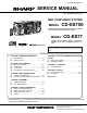
CD-ES700/CD-ES77 CD-ES700/CD-ES77 115 107 A 803x6 123 119 135 104 112 B 136 122 113 108 141 C 130 133 143 801x2 139 134 111 124 132 110 120 144 118 103 131 142 117 127 140 137 121 145 128 125 152 126 152 D 138 136 804 149 101 150 105 148 148 E 101 129 147 147 146 146 101 151 145 M1 M2 101 SW1 SW2 SW3 RX1 PWB-E 101 F 102 SW4 803x2 102 109-5 106 109-1 102 G 109 109-3 102 116 109-4 102 114 109-2 H 1 2 3 4 Figure 9 CHANGER MECHANISM EXPLODED V
CD-ES700/CD-ES77 CP-ES700/CP-ES77 A SP9, 10 SUPER TWEETER SP9, 10 SUPER TWEETER SP7, 8 SUPER TWEETER SP7, 8 SUPER TWEETER SP3, 4 TWEETER BL BK BK C1, C2 Capacitor 1.8 µF, 250 V Electrolytic SP3, 4 TWEETER B 903, 904 BL RD SP1,2 WOOFER C1, C2 Capacitor 1.
CD-ES700/CD-ES77 PACKING OF THE SET Setting position of switches and knobs Tape Mechanism STOP SPEAKER CP-ES700 CP-ES77 CD-ES700 CD-ES77 SPAKP0032AWZZ Polyethylene Bag, Unit P O T SSAKH0053AWZZ Polyethylene Bag, Speaker UNIT SPAKAA010AWZZ Packing Add., Left/Right P O T E SID RE AR E P O T SID FRONT HT FR RIG ON T SPAKAA013AWZZ Packing Add.