XL-HF201P SERVICE MANUAL No. S4212XLH201KU HI FI COMPONENT SYSTEM MODEL XL-HF201P(BK) XL-HF201P(BK) Hi Fi Component System consisting of XL-HF201P(BK) (main unit) and CP-HF200 (speaker system). • In the interests of user-safety (Required by safety regulations in some countries) the set should be restored to its original condition and only parts identical to those specified be used. iPhone, iPod, iPod classic, iPod nano, and iPod touch are trademarks of Apple Inc., registered in the U.S.
XL-HF201P PRECAUTIONS FOR USING LEAD-FREE SOLDER 1. Employing lead-free solder "MAIN, DISPLAY, KEY/JACK, iPod, USB, SMPS PWB" of this model employs lead-free solder. The LF symbol indicates lead-free solder, and is attached on the PWB and service manuals. The alphabetical character following LF shows the type of lead-free solder. Example: Indicates lead-free solder of tin, silver and copper. 2. Using lead-free wire solder When fixing the PWB soldered with the lead-free solder, apply lead-free wire solder.
XL-HF201P CHAPTER 1. GENERAL DESCRIPTION [1] Important Service Safety Precaution CAUTION : “These servicing instructions are for use by qualified service personnel only. To reduce the risk of electric shock do not perform any servicing other than that contained in the operating instructions unless you are qualified to do so”. WARNING 1. For continued safety, no modification of any circuit should be attempted. 2. Disconnect AC power before servicing. [2] Important Service Notes (for U.S.
XL-HF201P [3] Specifications USB (MP3 / WMA) General USB host interface Width: 8 - 1/2” (215 mm) Height: 3 - 4/5” (96 mm) Depth: 13 - 1/5” (335 mm) Complies with USB 1.1 (Full Speed)/2.0 Mass Storage Class. Support Bulk only and CBI protocol. Support file MPEG 1 Layer 3 WMA (Non DRM) 5.7 lbs. (2.6 kg) Bitrate support MP3 (32 ~ 320 kbps) WMA (64 ~ 160 kbps) Other Maximum total number of MP3/WMA files is 65025. Maximum total number of folders is 999 INCLUSIVE of root directory.
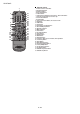
XL-HF201P [4] Names Of Parts Front panel 1 2 3 1. Remote sensor 2. Timer indicator 3. Disc Tray 4. Docking Station for iPod or iPhone 5. Volume Control 6. On/Stand-by Button 7. FUNCTION Button 8. USB Terminal 9. Audio In Socket 10. Headphone Socket 11. Tuner Preset Down, CD/USB Track Down, iPod/iPhone Skip Down 12. Tuner Preset Up, CD/USB Track Up, iPod/iPhone Skip Up 13. Disc/USB Stop Button 14. Disc/USB/iPod/iPhone Play or Pause Button 15.
XL-HF201P Remote control 1 2 3 4 5 6 7 8 9 10 11 12 13 14 15 16 17 18 19 20 21 22 23 24 25 26 27 28 29 30 31 32 33 1. Remote Control Transmitter 2. On/Stand-by Button 3. Numeric Buttons 4. Bass/Treble Button 5. X-Bass Button 6. Tuning Down, Skip Down, Fast Reverse, Time Down Button 7. Tuner Preset Up Button, iPod Cursor Up 8. Volume Down Button 9. Folder Button 10. Tuner Preset Down Button, iPod Cursor Down 11. CD Button 12. USB Button 13. iPod Button 14. iPod Display (TV OUT) Button 15.
XL-HF201P CHAPTER 2. ADJUSTMENTS [1] CD Section Items adjusted automatically • Adjustment Since this CD system incorporates the following automatic adjustment functions, readjustment is not needed when replacing the pickup. Therefore, different PWBs and pickups can be combined freely.
XL-HF201P CHAPTER 3. MECHANICAL DESCRIPTION Service Manual E Market CD-ES700/CD-ES77 [1] Disassembly Caution On Disassembly Follow the below-mentioned notes when disassembling the unit and reassembling it, to keep it safe and ensure excellent performance: 1. Take compact disc out of the unit. 2. Be sure to remove the power supply plug from the wall outlet before starting to disassemble the unit. 3. Take off nylon bands or wire holders where they need to be removed when disassembling the unit.
XL-HF201P STEP REMOVAL 1 Woofer (H1)x1 (H2)x1 Display PWB (H3)x1 (H4)x3 M2.6x8mm Key/Jack PWB Front Panel Assy 2 Dome-Tweeter (J1)x4 M2.6x8mm PROCEDURE FIGURE 1. Net Frame Ass'y .......(A1) X 1 7 2. Screw........................(A2) X 4 7 3. Screw........................(A3) X 4 8 4. Woofer Ring..............(A4) X 1 8 1. Screw........................(B1) X 4 8 2. Tweeter Ring ............(B2) X 1 8 2. Screw........................(B3) X 4 9 Speaker Box (K1)x1 M2.
XL-HF201P CHAPTER 4. FLOWCHART [1] Troubleshooting 1. When the CD does not function The CD section may not operate when the objective lens of the optical pickup is dirty. Clean the objective lens, and check the playback operation. When this section does not operate even after the above step is taken, check the following items. Remove the cabinet and follow the troubleshooting instructions.
XL-HF201P (1) Focus-RF system check. Although a CD is inserted and the cover is closed, "NO DISC" is displayed. 1 Press the Tray1 CD Eject Button without inserting a disc, and try starting the playback operation. IC1 FDO 102 IC1 2 TDO 101 Figure 1 1. Does the pickup move to the PICKUP-IN Switch (NSW1) position? Yes 2. Does the focus (lens) move up and down? (Waveform drawing Figure 1) No Sled motor (NM2). No Check the focus peripheral circuit.
XL-HF201P (2) Tracking system check Check the TE waveform at pin 16 on IC1. If the waveform shown in Figure 4 appears and soon after NO DISC appears? No "Initialization" is possible, but play is not possible? The tracking servo is not activated. Check the peripheral circuits at pins 98, 99, 101, 102 on IC1, and FFC1. Yes A normal jump operation cannot be completed or the beginning of the track cannot be found. Check the around pin 101 on IC1. Yes No "Initialization" is not possible.
XL-HF201P (4) PLL system check. When a disc is loaded, start play operation. 5 IC1 PLLF 126 PLLFO 6 The RF waveform is normal, but the TOC data cannot be read. 127 IC1 1 Check the PLL waveform. (Figure 6) FDO 102 IC1 Check around pins 125~ 128 on IC1.
XL-HF201P CHAPTER 5. MAJOR PART DRAWING [1] Function Table Of IC IC1 RH-IXA311AW00 : System Microcomputer ( 1/4 ) Pin No. 1 NAME H/P-SW Input/ Output TUN_SDA / DAP_SDA CMOS Input / Output HEADPHONE IN DETECTION SWITCH H : IN , L : OUT Input / Output CMOS Input / Output TUNER/DAP DATA I2C BUS LINE Input Input Input CMOS Input / Output 32.768kHz CRYSTAL (SUB CLOCK) Output CMOS Input / Output 32.768kHz CRYSTAL (SUB CLOCK) Input Input RESET INPUT.
XL-HF201P IC1 RH-IXA311AW00 : System Microcomputer ( 2/4 ) Pin No.
XL-HF201P IC1 RH-IXA311AW00 : System Microcomputer ( 3/4 ) Pin No. 57 NAME LEVEL_DET Input/ Output AREA 59 VSS Description Input (A / D) CMOS Input / Output ANALOG AUDIO LEVEL INPUT A/D DETECTION Input (A / D) CMOS Input / Output DESTINATION SETTING A/D INPUT -- -- Input (A / D) CMOS Input / Output -- -- A/D CONVERTER REFERENCE VOLTAGE SUPPLY -- -- 3.
XL-HF201P H/P-SW 1 iPod_EN KEY1 P0_1 / AN6 51 JOG_1/2 KEY2 P0_2 / AN5 52 P0_0 / AN7 50 CURRENT_LIMIT P0_3 / AN4 53 P1_0 / K10 / 49 AN8 USB_EN TIMER_LED P6_2 55 LEVEL_DETECT P0_4 / AN3 54 AREA P0_5 / AN2 / CLK1 57 AC_RELAY VSS P0_6 / AN1 / DA0 58 P6_1 56 SYS_PROTECT VSS / AVSS 59 VREF VREF 61 VCC P0_7 / AN0 / DA1 60 H/P MUTE P3_7 / SSO 63 VCC / AVCC 62 P3_5 / SCL / SSCK 64 TUN_SCL / DAP_SCL IC1 RH-IXA311AW00 : System Microcomputer ( IXA311AW ) ( 4/4 ) P3.
XL-HF201P [2] FL Display FL700 VVKNA16SM21-1 GRID ASSIGNMENT 16G 15G Dp Dp Dp Dp Dp Dp col col Dp 13G 14G 12G 11G 10G 9G 1-1 2-1 1-2 1-5 1-6 1-7 3-1 2-2 1-3 2-5 2-6 2-7 4-5 3-6 3-7 3G 2G 1G 5-4 5-5 4-6 4-7 4G 5-3 4-4 3-5 Dp 5G 5-2 4-3 3-4 Dp 6G 5-1 4-2 3-3 2-4 7G 4-1 3-2 2-3 1-4 Dp 8G 5-6 5-7 ANODE CONNECTION 16G 15G P1 P2 P3 P4 P5 P6 P7 P8 P9 P10 P11 P12 P13 P14 P15 P16 P17 P18 P19 P20 P21 P22 P23 P24 P25 P26 P27 P28 P29 P30 P31 P32 P33 P34 P35 14G 1
XL-HF201P CHAPTER 6.
XL-HF201P [2] Voltage Main PWB IC1 PIN NO 1 2 3 4 5 6 7 8 9 10 11 12 13 14 15 16 17 18 19 20 21 22 23 24 25 26 27 28 29 30 31 32 VOLTAGE (V) 1.73 24.00m 1.73 3.43 1.73 24.00m 24.10m 24.10m 1.62 1.66 3.43 3.43 1.22 3.43 1.22 23.80m 68.40m 25.00m 32.30m 3.43 34.90m 24.90m 1.63 1.65 3.43 25.7m 1.43 36.20m 35.80m 33.10m 33.10m 1.22 PIN NO 1 2 3 4 5 6 7 8 9 10 VOLTAGE (V) NC 4.34 NC 3.44 3.
XL-HF201P IC301 PIN NO 1 2 3 4 5 6 7 8 9 10 11 12 13 14 15 16 VOLTAGE (V) 1.83 101.00m 0.80 0.91 87.10m 87.10m 1.91 81.80m 3.25 1.29 3.11 3.20 3.10 51.00m 3.17 40.00m PIN NO 1 2 3 4 5 6 7 8 9 10 11 12 13 14 15 16 IC550 VOLTAGE (V) 18.20m 0.52 18.20m 2.39 16.20m 18.40m 18.40m 18.40m 25.50m 25.50m 1.07 18.40m 18.40m 16.40m 18.40m 11.57 PIN NO 1 2 3 4 5 6 7 8 9 10 11 VOLTAGE (V) 11.56 2.45 11.70m 38.00m 38.20m 38.40m 38.90m 40.30m 1.18 11.90m 18.
XL-HF201P IC600 PIN NO 1 2 3 4 5 6 7 8 9 10 11 12 13 14 15 16 VOLTAGE (V) 3.20 3.20 3.11 1.38 0.79 3.05 1.65 2.80m 1.51 3.08 3.08 3.08 5.50m 3.07 4.60m 1.44 PIN NO 17 18 19 20 21 22 23 24 25 26 27 28 29 30 31 32 VOLTAGE (V) 3.08 3.17 50.30m 7.30m 7.30m 11.50m 7.10m 3.53 2.54 9.20m 1.79 7.80m 7.60m 291.90m 3.18 162.00m PIN NO 1 2 3 4 5 6 7 VOLTAGE (V) 1.73 4.23 3.00 1.73 1.25 0.28m 0.28m PIN NO 8 9 10 11 12 13 14 VOLTAGE (V) 0.28m 4.92 26.00m 2.54 3.81 2.57 2.
XL-HF201P -MEMO- 6–5
XL-HF201P CHAPTER 7.
XL-HF201P -MEMO- 7–2
XL-HF201P -MEMO- 7 – 31
XL-HF201P CHAPTER 8. CIRCUIT SCHEMATICS AND PARTS LAYOUT [1] Notes On Schematic Diagram • • Resistor: To differentiate the units of resistors, such symbol as K and M are used: the symbol K means 1000 ohm and the symbol M means 1000 kohm and the resistor without any symbol is ohm-type resistor. Besides, the one with “Fusible” is a fuse type. Capacitor: To indicate the unit of capacitor, a symbol P is used: this symbol P means pico-farad and the unit of the capacitor without such a symbol is microfarad.
XL-HF201P [3] Schematic Diagram MAIN PWB-A1 A A042AW B C TOP ENTRY YP12AW CNP601 JP502 0 D JP501 0 0 2.2K R544 10K R548 10K R547 E JP903 C549 0.1u Q520 2875B C536 1000P 1000P 2875B C537 Q521 2.2K R543 KRC104S Q632 Q522 22K R549 CM201GA 2.2/50 KRA102S R992 C538 C569 0.1u C553 0.1u C944 0.1u 000 F JP902 JP901 47p G 47p C552 0.1u C943 0.1u CHASIS GND LUG 902 C945 0.
XL-HF201P MAIN PWB-A1 CD Section A B C TO iPod TERMINAL D USB IN TERMINAL FROM CD PICK-UP UNIT E C39 C40 33p 33pF (MCLKO) C91 (47p) F G H 1 2 3 4 5 7 6 Figure 8-2: MAIN (CD) SCHEMATIC DIAGRAM 8–3 8 9 10 11 12
XL-HF201P DISPLAY PWB-A2 A B C C704 1u D701 DA1010 DA1010 D700 D LUG 700 NB709AWPZ FROM SMPS PWB E FROM MAIN PWB F G H 1 2 3 4 5 6 7 Figure 8-3: DISPLAY SCHEMATIC DIAGRAM 8–4 8 9 10 11 12
XL-HF201P USB PWB-A5 iPod PWB-A4 TO MAIN PWB-A1 A B C 0 FROM EXTERNAL iPod DEVICE ONLY FB403 KEY/JACK PWB-A3 TO DISPLAY PWB-A2 D LUG401 NB708AWPZ E STOP FF PLAY / PAUSE REW AUDIO IN OPEN / CLOSE 8 TO MAIN PWB-A1 F 7 HEADPHONE IN 6 B708 5 C429 0.1 G 0.
XL-HF201P [4] Chart Of Connecting Wires Bi400 1 2 3 4 5 BK WH PK YL 1 A FROM EXTERNAL USB DEVICE ONLY JK400 GY LUG401 USB PWB-A5 FROM EXTERNAL iPod DEVICE ONLY YL PK WH BK TO CHASSIS L-CH (+/-) SPEAKER TERMINAL BK WH BL GR BK PK WH WH PK BK GR BL WH BK GY GY SHIELDED CNP201 Bi201 CNP7 SC600 CNS201 1 2 3 4 5 6 7 1 2 3 4 5 6 7 CNP5 4 3 2 1 B 8 7 6 5 4 3 2 1 CNS5 4 3 2 1 MAiN PWB-A1 TO SMPS CNP902 iPod PWB-A4 R-CH (+/-) RD WH BK WH CNP501 FL700 FL DISPLAY TO CD PICK-UP UNIT B
XL-HF201P [5] Wiring Side Of PWB A MAIN PWB-A1 3 1 4 2 B 1 2 3 4 5 6 7 8 9 10 C 1 23 4 5 6 7 D 1 23 4 5 11 9 7 5 3 1 12 10 8 6 4 2 E WIRE A 5 4 32 1 4 32 1 F G 65 4 32 1 1 23 4 5 6 7 2 4 6 8 10 12 14 16 1 3 5 7 9 11 13 15 BOTTOM VIEW TOP VIEW Lead-free solder indication H Lead-free solder is used in the MAIN PWB. Refer to "Precautions for handling lead-free solder" for instructions and precautions.
XL-HF201P A DISPLAY PWB-A2 11 9 7 5 3 1 12 10 8 6 4 2 B 2 1 C 1 2 3 4 5 TOP VIEW D E F BOTTOM VIEW G Lead-free solder indication H Lead-free solder is used in the DISPLAY PWB. Refer to "Precautions for handling lead-free solder" for instructions and precautions.
XL-HF201P A KEY / JACK PWB-A3 B 1 2 C 1 2 3 4 5 6 7 8 TOP VIEW D E F BOTTOM VIEW G Lead-free solder indication H Lead-free solder is used in the KEY / JACK PWB. Refer to "Precautions for handling lead-free solder" for instructions and precautions.
XL-HF201P iPod PWB-A4 12345678 A B 30 1 C TOP VIEW BOTTOM VIEW Lead-free solder indication D Lead-free solder is used in the iPod PWB. Refer to "Precautions for handling lead-free solder" for instructions and precautions. USB PWB-A5 E F 1 2 3 4 5 G TOP VIEW BOTTOM VIEW Lead-free solder indication H Lead-free solder is used in the USB PWB. Refer to "Precautions for handling lead-free solder" for instructions and precautions.
XL-HF201P -MEMO- 8 – 11
XL-HF201P -MEMO- –1 8 – 12
XL-HF201P PARTS GUIDE HI FI COMPONENT SYSTEM MODEL XL-HF201P(BK) XL-HF201P(BK) Hi Fi Component System consisting of XL-HF201P(BK) (main unit) and CP-HF200 (speaker system). CONTENTS [1] INTEGRATED CIRCUITS [8] OTHER CIRCUITRY PARTS [2] TRANSISTORS [9] CABINET PARTS / CD MECHANISM PARTS [3] DIODES [4] COILS [5] CRYSTALS / VIBRATORS [11] ACCESSORIES / PACKING PARTS [6] CAPACITORS [12] P.W.B.
XL-HF201P NO.
XL-HF201P NO.
XL-HF201P NO.
XL-HF201P NO.
XL-HF201P NO.
XL-HF201P NO.
XL-HF201P NO.
XL-HF201P NO.
XL-HF201P NO.
XL-HF201P [9] CABINET PARTS / CD MECHANISM PARTS 610 x 4 610 223 x 2 204 A 216 202 217 B 610 PWB-A4 208 220 604 x 2 606 227 221 610 x 2 229 610 610 604 x 2 C PWB-A1 209 218 604 x 2 601 x 4 226 209 218 225 224 IC803 D 602 610 x 7 215 607 PWB-A2 302 603 x 3 302-1 E 214 205 FL 203 210 PWB-A3 609 PWB-B 603 x 4 605 x 4 F 603 301 PWB SPACER 201 219 PWB-A5 609 604 302 - 2x4 231 212 302 - 3x4 201 - 2 201 - 1 302 - 4x4 230 609 228 G 201 - 3 213 609 x 2 206 x 4
XL-HF201P NO.
XL-HF201P [10] SPEAKER BOX PARTS 903 913 x 4 A SP3 x 4 914 x 4 913 x 4 B 905 SP1, 2 901 C 911 902 904 908 x 2 D 912 x 4 909 x 2 906 x 4 E F 907 x 4 DOME-TWEETER SP3 (L-CH) SP4 (R-CH) RED BK G BK 910 C1, 2 Capacitor RED DOME-TWEETER SP3 (L-CH) SP4 (R-CH) TERMINAL BK C1, 2 Capacitor 4.
XL-HF201P NO.
XL-HF201P [11] ACCESSORIES / PACKING PARTS PACKING METHOD (FOR U.S.A ONLY) Front Speaker (L/R) UNIT Label, POP TLABZB423AWZZ Polyethylene Bag, Unit SSAKHA173AWZZ Polyethylene Bag, Speaker SSAKHA087AWZZ Packing Add., Front Speaker, Top SPAKAA256AWZZ Packing Add., Unit, Rear SPAKAA412AWZZ Packing Add., Unit, Front SPAKAA328AWZZ A Packing Add.
XL-HF201P COPYRIGHT 2012 BY SHARP CORPORATION ALL RIGHTS RESERVED. No part of this publication may be reproduced, stored in a retrieval system, or transmitted in any form or by any means, electronic, mechanical, photocopying, recording, or otherwise, without prior written permission of the publisher. SHARP CORPORATION S&O Electronics (Malaysia) Sdn. Bhd.