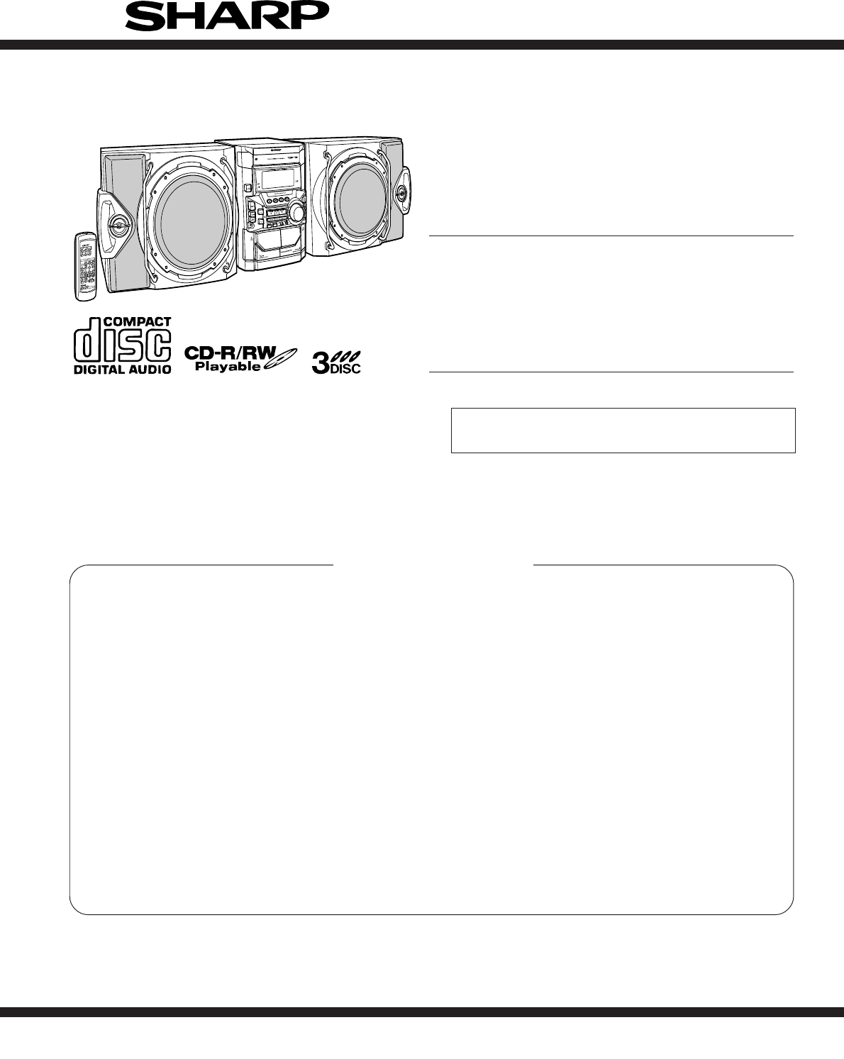
CD-M4000W/CP-M4000 SERVICE MANUAL No. S9156CDM4000W MINI COMPONENT SYSTEM MODEL CD-M4000W SPEAKER SYSTEM MODEL CP-M4000 • In the interests of user-safety the set should be restored to its original condition and only parts identical to those specified be used. CONTENTS Page SAFETY PRECAUTION FOR SERVICE MANUAL ........................................................................................................... 2 VOLTAGE SELECTION ..................................................................
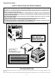
CD-M4000W/CP-M4000 SAFETY PRECAUTION FOR SERVICE MANUAL WARNINGS THE AEL (ACCESSIBLE EMISSION LEVEL) OF THE LASER POWER OUTPUT IS LESS THAN CLASS 1 BUT THE LASER COMPONENT IS CAPABLE OF EMITTING RADIATION EXCEEDING THE LIMIT FOR CLASS 1. THEREFORE IT IS IMPORTANT THAT THE FOLLOWING PRECAUTIONS ARE OBSERVED DURING SERVICING TO PROTECT YOUR EYES AGAINST EXPOSURE TO THE LASER BEAM.
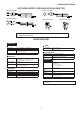
CD-M4000W/CP-M4000 AC POWER SUPPLY CORD AND AC PLUG ADAPTOR QACCL0005AW00 QACCA0003AW00 QACCE0008AW00 QPLGA0003AWZZ QPLGA0004AWZZ FOR A COMPLETE DESCRIPTION OF THE OPERATION OF THIS UNIT, PLEASE REFER TO THE OPERATION MANUAL. SPECIFICATIONS CD-M4000W General Power source Power consumption Dimensions Weight Tuner AC 110/127/220/230 - 240 V, 50/60 Hz Frequency range 120 W Width: 270 mm (10-5/8") Height: 330 mm (13") Depth: 372 mm (14-11/16") 9.4 kg (20.7 lbs.
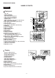
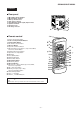
CD-M4000W/CP-M4000 NAMES OF PARTS CD-M4000W Front panel 6 1. Disc Tray 2. Timer Set Indicator 3. On/Stand-by Button 4. Tape 2 Cassette Compartment 5. Tape 1 Cassette Compartment 6. Equalizer Mode Select Button 7. Volume Control 8. Monster Bass/Demo Mode Button (with Indicator) 9. Disc Tray Open/Close Button 10.Disc Number Select Buttons (with Indicator) 11.Disc Skip Button 12.Tuning and Time Up Button 13.Tape 2 Reverse Play Button (with Indicator) 14.CD Button 15.Tuner (Band) Button 16.
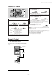
CD-M4000W/CP-M4000 CD-M4000W Rear panel 1. FM 75 Ohms Aerial Terminal 2. FM Aerial Earth Terminal 3. AM Loop Aerial Socket 4. Span Selector Switch 5. Video/Auxiliary (Audio Signal) Input Sockets 6. Speaker Terminals 7. AC Power Lead 8. AC Voltage Selector 1 2 3 4 5 6 8 Remote control 7 1 1. Remote Control Transmitter 2. Echo Level Up and Down Buttons 3. Karaoke Mode Button 4. Disc Number Select Buttons 5. CD Clear Button 6. Tape 2 Record Pause Button 7.
CD-M4000W/CP-M4000 CP-M4000 Speaker system 1 1. Tweeter 2. Super Tweeter 3. Midrange 4. Woofer 5. Bass Reflex Duc 6. Speaker Terminals 2 5 4 3 OPERATION MANUAL System Connections Setting the AC voltage selector Setting the FM/AM span selector Check the setting of the AC voltage selector located on the rear panel before plugging the unit into a wall socket. If necessary, adjust the selector to correspond to the AC power voltage used in your area.
CD-M4000W/CP-M4000 Setting the Clock 4 Press the TUNING/TIME ( or ) button to adjust the hour and then press the MEMORY/SET button. Press the TUNING/TIME ( or ) button once to advance the time by 1 hour. Hold it down to advance continuously. When the 12-hour display is selected, "AM" will change automatically to "PM". 5 Press the TUNING/TIME ( or ) button to adjust the minutes and then press the MEMORY/SET button. In this example, the clock is set for the 24-hour (0:00) display.
CD-M4000W/CP-M4000 Troubleshooting Chart Many potential problems can be resolved by the owner without calling a service technician. If something is wrong with this product, check the following before calling your authorised SHARP dealer or service centre. General Cassette deck Symptom Cannot record. Possible cause Is the erase-prevention tab removed? Cannot record tracks with proper sound quality. Is it a normal tape? (Yo u cannot record on a metal or CrO tape.
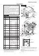
CD-M4000W/CP-M4000 DISASSEMBLY CD-M4000W Caution on Disassembly Follow the below-mentioned notes when disassembling the unit and reassembling it, to keep it safe and ensure excellent performance: 1. Take cassette tape and compact disc out of the unit. 2. Be sure to remove the power supply plug from the wall outlet before starting to disassemble the unit. 3. Take off nylon bands or wire holders where they need to be removed when disassembling the unit.
CD-M4000W/CP-M4000 (H1) x 1 Clamp Lever Display PWB (H3) x 1 (L1) x 2 ø3 x 10mm (H2) x 12 ø3 x 10mm Mic PWB CD Player Unit (Top View) Tape Mechanism Front Panel Lug Wire Cam Gear Rib Open (J1) x 5 ø3 x 10mm Cassette Holder Figure 10-1 (K1) x 1 ø3 x 10mm Lug Wire (E3) x 1 Headphones PWB (E3) x 1 Figure 10-4 (M2) x 1 Power (F2) x 1 PWB (E2) x 1 Mic PWB Transformer PWB Turntable Main PWB Main PWB Slide Chassis (F2) x 1 (E3) x 1 (M1) x 2 Amp.
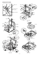
CD-M4000W/CP-M4000 (Q2) x 3 CD Mechanism (P1) x 1 ø3 x 8mm CD Servo PWB Slide Chassis (P3) x 2 (Q1) x 1 (Q1) x 1 (P2) x 2 CD Mechanism Chassis (P3) x 2 Slide Chassis Figure 11-1 Figure 11-2 CP-M4000 STEP 1 REMOVAL Front Panel PROCEDURE FIGURE Speaker Box Ass'y 1. Net .......................... (A1) x1 11-3,11-4 2. Catching Holder ..... (A2) x4 3. Screw ..................... (A3) x4 2 Super Tweeter 1. Screw ..................... (B1) x2 11-5 3 Woofer 1. Screw .....................
CD-M4000W/CP-M4000 REMOVING AND REINSTALLING THE MAIN PARTS TAPE 2 TAPE MECHANISM SECTION Clutch Ass'y Perform steps 1 to 7 and 9 of the disassembly method to remove the tape mechanism. Record/Playback Head How to remove the record/playback and erase heads (TAPE 2) (See Fig. 12-1) Erase Head 1. When you remove the screws (A1) x 2 pcs., the recording/ playback head and three-dimensional head of the erasing head can be removed. How to remove the playback head (TAPE 1) (See Fig.
CD-M4000W/CP-M4000 CD MECHANISM SECTION Perform steps 1, 2, 3, 12, 13, 14 and 15 of the disassembly method to remove the CD mechanism. Slide Chassis How to remove the CD loading motor (See Fig. 13-1) CD Loading Motor CD Loading Motor PWB (A1) x 1 (A1) x 2 1. Bend the hooks (A1) x 5 pcs., to remove the CD loading motor. 2. Remove the drive belt (A2) x 1 pc. (A1) x 2 CD Loading Motor Pulley Drive Belt (A2) x 1 Figure 13-1 How to remove the pickup (See Fig. 13-2) Stop Washer (B3) x 2 (B1) x 1 ø2.
CD-M4000W/CP-M4000 • FM RF Signal generator: 1 kHz, 40 kHz dev., FM modulated TUNER SECTION fL: Low-range frequency fH: High-range frequency • AM IF/RF Signal generator: 400 Hz, 30%, AM modulated Test Stage Frequency Frequency Display Setting/ Instrument Adjusting Connection Parts AM IF 450 kHz 1,602 kHz T351 AM Band Coverage — 531 kHz (fL): T306 *2 1.1 ± 0.1 V 990 kHz (fL): T303 AM Tracking 990 kHz *1. Input: Antenna *2. Input: Antenna FM Band Coverage — FM RF 98.00 MHz 98.
CD-M4000W/CP-M4000 TEST MODE • Setting the test mode Any one of test mode can be set by pressing several keys as follows. + + TEST:CD operation test Function:-CD test mode. -Enter test mode. C D T E S T IL isn't done OPEN/CLOSE operation is using manual. << >>, << >> buttons make pick's slide possible. <> key input. Do TOC IL.
CD-M4000W/CP-M4000 Standard Specification of Stereo System Error Message Display Contents Error Contents Display Output while Device Protection Operation 'PROTECT' Notes 00: While in Protect Circuit Operate 01: Over Current Detection 02: DC Detection 03: TAPE Mechanism Error 'ER-TA**' 00: Tape Mechanism Error 01: Initial Error 02: 03: CD/VCD Pickup Mechanism Error 'ER-CD**' 00: Pickup Mechanism Error 01: PU-IN SW Detection NG 02: 03: CD Changer Mechanism Error 'ER-CD**' 10: Changer Error 11:
CD-M4000W/CP-M4000 5 6 7 8 9 3 4 5 6 1 2 3 4 5 6 CNS4 4 2 1 2 3 4 5 6 CNP4 OC, DISC NO 3 1 1 2 17 25 FD CLAMP SW 2 M3 CD LOADING SLDO CD RES 1 CNP8 CL 6 DI 5 DO +5V (+B5 ) 4 CE +5V (+B5) 3 DRF DGND 2 WRQ AGND 1 M TO DISPLAY SECTION L-CH R-CH CNP7 TO MAIN SECTION BI4 SW3 SW2 DISC CLAMP NUMBER SW1 OPEN/ CLOSE Q3 CONT3 CONT4 75 69 57 63 DI 56 64 DO 55 65 VWRQ 51 50 66 VRES 40 67 DRF IC1 LC78645E CD SERVO 37 28 19 SLDO 23 9 10 LDD
CD-M4000W/CP-M4000 FM ANTENNA TERMINAL +B4 10.7MHz FM IF 7 8 FM L312 RF IC303 LA1832S FM IFDET./ FM MPX./ AM IF T301 AM OSC IN FM OSC AM LOOP ANTENNA OSC BUFF Q302 CNP301 AM TRACKING 2 1 T306 T303 AM BAND COVERAGE X352 4.5MHZ VT CE ICK1 M65856SP MIC AMP. JK1 MIC 20 1 22 15 16 OSC LATCH 40 +B4 L OUT 36 9 R OUT 35 8 6 VCC 23 5 6 17 21 JK601 VIDEO/AUX L-CH R-CH 2 IC101 PLAYBACK AND RECORD/ PLAYBACK AMP. 3 L L(T1) 1 R(T1) 24 SWITCHING REC P.B. Q103Q106 P.
CD-M4000W/CP-M4000 FL701 FL DISPLAY +B4 6 ~ 13 1 2 3 14 ~ 16 23 ~ 32 33 ~ 44 JOG701 JOG VOLUME 56 57 58 Q701-Q703 +B5 +B5 57 56 55 54 53 52 51 50 49 48 +B6 46 45 44 43 42 41 40 VDD 61 RX701 1 REMOTE SENSOR 3 2 67 - 78 79 VLOAD 80 - IC701(1/2) IX0460AW SYSTEM MICROCOMPUTER 89 KEY SW701-SW703 SW709-SW717 SW722-SW734 IC702 BU2092F INPUT/OUTPUT +B5 EXPANDER 1 18 2 IC702 - 90 39 38 37 36 35 +B5 AVDD 34 33 - 31 1 2 4 5 6 7 9 10 11 12 13 15 16 17 +B5 +B6 20 21 22 23 24 3 22 58 4
CD-M4000W/CP-M4000 A PICKUP UNIT CD SERVO PWB-C M PU-IN R11 10K C3 47/25 R13 1K 7 6 5 4 R14 FD 8 FO+ 9 FO– 21 20 19 18 17 16 15 14 13 12 11 10 TR+ MUTE 3 2 IC2 M63001FP FOCUS/TRACKING/ SPIN/SLED DRIVER – + SP+ 6 SP– 5 4 SL+ SL– 3 PUIN 2 1 GND CNP3 1 TR– 6 5 4 3 2 1 C39 100/10 SL– 1 2 3 4 5 6 CT2 0.001 1 2 3 TP3 R12 4 330 C8 5 0.0047 6 7 TP1 C50 8 22P TP2 9 (CH) 10 C10 11 10/50 C9 12 100/10 13 C11 0.22/50 14 15 4 16 C12 17 100P 18 19 20 GND 1 2 3 4 5 6 C6 0.
CD-M4000W/CP-M4000 3 C34 100P C32 100P R38 R37 R36 R35 R34 R33 R32 C30 100P 2 R31 1K C13 0.022 11 R28 2.2K 60 DATA 59 DATACK 58 10 57 56 55 54 XL1 53 33.8688 MHz 52 51 50 R43 49 220 48 47 R22 46 100 45 ZD1 DZ3.3BSB 44 C24 43 C16 10/50 42 330/6.3 R25 LVDD 41 2.2K C23 C44 C26 0.001 10/50 0.0015 R24 R27 2.2K 10K C25 0.0015 C14 100/10 SBCK/FG DEFECT V/*P FSEQ MONI1 MONI2 MONI3 MONI4 MONI5 VSS VDD DOUT TEST R18 1K R20 10K 1 12 C51 0.022 C42 0.
CD-M4000W/CP-M4000 +B 1 DI C606 100/16 2 CLK CE CCB 3 VSS C609 0.22(ML) 4 VREF + – INTERFACE LOUT ROUT + – Q605 KTC3199 GR R622 Q606 2.2K KTC3199 GR LVL-CTRL 4 +B 5 R611 1.5K R613 220 R615 2.2K C615 0.001 C616 0.001 R616 2.2K R614 220 C105 180P 0V R105 3.3K 0.7V 0V R103 2.2K Q103 2SC1845 F 0V 0V 2 3 R171 1K 5 6 + – R874 100K 16 – + 56K Hich=CHROME 56K + – 8 9 C145 22/50 C146 220/10 R146 10K C142 47/25 C132 270P 7 17 C115 100/25 15 14 10 11 12 C127 0.
CD-M4000W/CP-M4000 CLK 24 VDD 23 VREF ROUT C602 22/25 22 C614 R608 10/50 10K R606 C608 3.9K 0.22 (ML) C612 C620 0.0015 1/50 21 C610 0.22(ML) 20 RBASS 19 RIN RSEL0 R4 RTRE 18 C622 10/50 C624 1/50 17 16 R3 15 R2 14 MAIN PWB-A(1/2) FM SIGNAL PLAYBACK SIGNAL RECORD SIGNAL CD SIGNAL VIDEO SIGNAL MIC SIGNAL +B R633 39K R631 8.2K C631 390P R632 8.2K C632 390P L-CH JK601 VIDEO/AUX R634 39K R-CH CHASSIS C626 1/50 C641 0.0033 C628 1/50 R618 4.7K R1 13 BI11 R623 4.
CD-M4000W/CP-M4000 DISPLAY PWB-B1 A P04 P03 P01 G11 16 81 82 83 84 85 86 87 88 89 90 P3 P2 P02 P05 24 23 P06 25 P07 26 P08 28 27 P09 29 P10 P11 P12 P13 36 35 34 33 32 R716 100K Q703 KTC3199 GR C714 47/50 R724 33 R719 1K R705 1K 80 P10 G11 C715 22/50 P1 Q702 KTC3199 GR R702 1K 31 30 P4 38 37 P14 P15 P16 P17 P18 40 39 P5 41 P6 42 P19 P20 P21 P22 43 P9 Q701 KTC3199 GR 44 P7 B R704 100K 57 56 P8 R701 100K F 58 F F FL701 FL DISPLAY 79
CD-M4000W/CP-M4000 TO CD SERVO PWB P21 12-B C722 47/50 G9 G8 1 R773 2 DSA_STB 3 T-BIAS 4 T-T1/T2 5 REC/PLAY 6 RES OUT 7 DRF 8 WRQ 9 1K 7 8 9 1 2 3 4 5 6 7 8 9 CNS703 C725 0.022 CNS705 VF1 -VF R775 R776 RESET 10 1K VF2 1K P_IN R777 1K R778 1K R779 1K R780 1K R781 1K X2 11 X1 12 XL701 4.
CD-M4000W/CP-M4000 7 6 5 C957 100/100 R951 3.9K D908 DS1SS133 D907 DS1SS133 R921 1.8K R935 47K R919 1.5K VL+ R917 0.1 (3W) R906 1K R911 100 (1/4W) Fusible R910 56K C902 3300/71 VH– C918 0.22/50 C917 0.22/50 C904 4700/35 VL– D902 DS1N404S SP DET C958 0.1/50 C901 3300/71 R905 1K R952 3.9K R936 47K Q902 KTC3199 GR R922 1.8K Q901 KTC3199 GR C940 220P C921 100/50 R920 1.5K D909 DS1SS133 ZD901 DZ12BSB C903 4700/35 C922 100/50 C919 100/100 C924 0.
CD-M4000W/CP-M4000 AMP. PWB-D2 C937 0.1 C930 0.1 (ML) R930 56K D911 DS1SS133 R932 10 (1/2W) 2 1 3 R934 2.2K C928 0.1 (ML) C936 0.1 R948 3.9 (1/2W) CHASIS GND LG901 CHASIS GND R933 2.2K CNP904 +B L902 0.29µH D912 DS1SS133 R942 560 (2W) L-CH C938 0.1 R941 560 (2W) R937 15K C943 47/50 Q907 KTC3203 Y FAN MOTOR DRIVER R939 2.
CD-M4000W/CP-M4000 AM LOOP ANTENNA SO301 FM ANTENNA TERMINAL A 2 1 CNP301 2 1 R311 R314 22 C309 0.001 100K VD302 KDV147B R313 33K C317 0.001 B IC301 TA7358AP 3 FM FRONT END 4 C323 0.022 5 +B 6 C312 0.022 +B R322 680 Q302 KTC3194 Y 7 T301 FM OSC. R325 47K OSC BUFF T302 C324 8.2P(UJ) FM IF C318 100P 1 2 CF303 R316 4.7K AM SIGNAL 9 C306 0.
CD-M4000W/CP-M4000 MIC PWB-H MIC SIGNAL RK4 10K RK5 1K CK6 0.1 CK7 0.47 CK8 4.7/50 CK9 2.2/50 5.6K JK1 MIC CK2 0.47 CK10 RK8 RK7 1K VRK1 CK11 20K(B) MIC CK13 VOLUME 0.0047 CK14 RK11 1K CLOCK 41 RK10 1K 3 VACL LATCH 40 RK9 1K 4 MIC1 IN PS2 39 5 ALC1 PS1 38 6 MIC1NF IN VCF IL 37 7 MIC1 OUT L OUT 36 8 MIC1VOL IN R OUT 35 47P CK34 47P CK33 0.15 2.2/50 CK30 2.2/50 RK43 18K 0.1 12 MIC2 OUT L IN 31 CK25 2.2/50 0.1 13 MIC2VOL IN VOL IN 30 CK24 2.
CD-M4000W/CP-M4000 TO MIC PWB P29 12-G CNP7 CNPK1 CNS602 CNS11 1 2 3 4 5 6 RD WH GY WH GY WH MAIN PWB-A 1 2 3 4 5 6 7 8 9 10 RD GY WH GY WH GY WH GY WH GY A TO CD SERVO PWB P36 5-A B R373 R378 R374 R379 C397 L351 R375 C386 C391 C396 R377 11 13 17 19 21 12 14 16 18 20 C363 R627 R626 SW601 SPAN SELECTOR R606 9 kHz/50 kHz R364 R607 R634 JK601 VIDEO/AUX IN L-CH C616 R619 R-CH C632 R632 R616 R631 C631 R633 R613 Q603 E C B B C E Q604 B C E R614 G C614 E Q605 C R621 B C602
CD-M4000W/CP-M4000 TO DISPLAY PWB P33 11-A CNP701 10 GY FC701 21 1 Q122 R156 B C E C146 R140 R158 R146 C142 R154 R153 C145 Q121 R145 B C E 13 15 17 19 21 Q865 B C E 12 Q864 14 3 2 1 16 18 20 R125 R131 C127 C115 C121 C119 R123 R870 C117 C867 C861 R866 C865 D864 1 5 R861 3 6 2 7 1 8 CNP101 IC860 R873 R880 R867 1 C101 C863 D862 R874 6 B C E R868 1 2 3 1 2 3 Q862 Q110 1 2 3 R155 R122 E C B R105 E C B R103 Q104 E C B BI102 7 WH BK PK BK WH YL BL CNS
CD-M4000W/CP-M4000 DISPLAY PWB-B1 1 2 3 CNS703 R701 R704 R716 C722 Q701 Q703 B B B C C C E E E C714 1 R702 R705 R719 Q709 RX701 R781 3 2 1 4 BI705 C729 3 2 1 RS720 LED706 IC703 8 7 6 5 CS711 1 2 3 4 RS716 RS708 RD10 RD11 F CS705 RD12 R779 R780 R736 C721 RS715 C720 B C E B C E B Q708 RD14 C E SW7 EQU D713 D712 C719 RD15 LED708 CNP702 RD36 RD1 R737 JOG701 SW711 DISC 3 SW733 VIDEO R752 R795 R757 SW715 MONSTER BASS R782 R778 R773 R775 R776 R777 RS711 CS710 CS707 D704 LED7
CD-M4000W/CP-M4000 TO MAIN PWB P31 9-A CNP601 23 24 25 26 27 28 29 30 31 32 33 34 35 36 37 38 39 40 41 42 43 44 R727 R728 FL701 81 85 75 70 25 35 R721 R758 R790 R789 R788 R787 RD06 R740 R766 R700 LED722 R756 R755 R772 R771 R769 R768 C726 D720 R762 R767 RL704 RL703 R783 R784 R785 R786 R791 R770 R747 R748 R753 40 31 30 R751 50 20 SW701 ON/ STAND-BY R764 R763 R765 R759 R754 15 R743 51 55 45 R746 60 IC701 R720 R718 R714 R717 R713 R792 5 10 R749 1 D721 R793 65 R744 R7
CD-M4000W/CP-M4000 TRANSFORMER PWB-D3 AC POWER SUPPLY CORD AC 110/127/220/ 230-240 V, 50/60 Hz A 230-240V 220V 110V 127V COLOR TABLE GR GREEN BL BLUE VL VIOLET GY GRAY WH(W) WHITE BK BLACK PK PINK LG801 LG802 110 V YELLOW 127 V YL 220 V ORANGE F803 T2.5A L 250 V RED OR 230-240 V C RD(R) F801 T5A L 250 V B BROWN F802 T2.5A L 250 V BR SW801 VOLTAGE SELECTOR T.
CD-M4000W/CP-M4000 SO901 SPEAKER TERMINAL L-CH R-CH AMP.
CD-M4000W/CP-M4000 P32 1-B FROM DISPLAY PWB CNP703 CD SERVO PWB-C A P30 4-A FROM MAIN PWB CNS11 3 E C B R9 7 C1 C6 R32 R22 R33 70 75 80 1 R5 R2 5 45 IC1 C39 R6 R3 R44 C44 C12 R20 1 20 15 10 C9 5 C40 25 C10 30 35 1 2 Q3 D2 D1 CNP4 6 5 4 3 2 1 CNP3 6 5 4 3 2 1 4 R46 R45 42 C41 3 40 22 E 6 R18 R30 R17 IC2 9 20 21 C11 21 10 R24 R26 C25 C13 CT1 CT2 C23 30 15 25 R1 11 C26 41 40 C16 35 12 C48 R27 R25 C24 65 55 50 10 R4 R65 D R43 C14 C50 R49
CD-M4000W/CP-M4000 P32 4-B TO DISPLAY PWB TAPE MECHANISM ASSEMBLY CNS703 FC702 1 SW TAPE MECHANISM PWB-F 9 SW 1 3 5 7 9 2 4 6 8 SW SW PH 1 2 SOLENOID + - SOLENOID TAPE MOTOR TAPE 1 PLAYBACK HEAD PK WH BK TAPE 2 RECORD/PLAYBACK/ERASE HEAD PK WH BK GR 654321 3 2 1 CNP101 CNS102 P31 12-D FROM MAIN PWB P31 12-F TO MAIN PWB COLOR TABLE CD LOADING MOTOR PWB-E WH BK WH BK WH RD 6 5 4 3 2 1 M3 CD LOADING MOTOR CNS4 6 1 BI4 + – SW3 DISC NUMBER 7 SW1 OPEN/ CLOSE SW2 CLAMP 8
CD-M4000W/CP-M4000 VOLTAGE IC1 PIN NO. 41 42 43 44 45 46 47 48 49 50 51 52 53 54 55 56 57 58 59 60 61 62 63 64 65 66 67 68 69 70 71 72 73 74 75 76 77 78 79 80 IC101 PIN NO. 1 2 3 4 5 6 7 8 9 10 11 12 13 14 15 16 17 18 19 20 21 22 23 24 25 26 27 28 29 30 31 32 33 34 35 36 37 38 39 40 VOLTAGE VOLTAGE 1.6 V 1V 1.6 V 1.8 V 3.3 V 0V 1.6 V 1.6 V 1.6 V 1.6 V 1.6 V 1.6 V 1.5 V 1.5 V 1.5 V 1.5 V 0.8 V 3.2 V 0V 1.6 V 1.6 V 1.6 V 1.6 V 0V 0V 3.2 V 0V 0V 0V 0V 0V 0V 0V 0V 1.6 V 0V 0V 3.2 V 3.2 V 0V 3.7 V 3.
CD-M4000W/CP-M4000 NOTES ON SCHEMATIC DIAGRAM • Resistor: To differentiate the units of resistors, such symbol as K and M are used: the symbol K means 1000 ohm and the symbol M means 1000 kohm and the resistor without any symbol is ohm-type resistor. Besides, the one with “Fusible” is a fuse type. • Capacitor: To indicate the unit of capacitor, a symbol P is used: this symbol P means pico-farad and the unit of the capacitor without such a symbol is microfarad.
CD-M4000W/CP-M4000 WAVEFORMS OF CD CIRCUIT Stopped CH1=500 mV DC 10:1 CH3=500 mV DC 10:1 T 1 IC1 21 Stopped CH1=200 mV DC 10:1 500 ms/div (500 ms/div) NORM:20 kS/s IC1 20 1999/04/07 09:51:15 500 ms/div (500 ms/div) NORM:20 kS/s FDO T 1 TDO 2 T CH2=500 mV DC 10:1 3 FDO 1 IC1 21 2 6 IC1 22 1 SPDO CH1 v/DIV 500 mV =Filter= Smoothing : ON BW : FULL =Offset= CH1 : 0.000 V CH2 : 0.0 V CH3 : 0.000 V CH4 : 0.
CD-M4000W/CP-M4000 TROUBLESHOOTING When the CD does not function When the CD section does not operate when the objective lens of the optical pickup is dirty, this section may not operate. Clean the objective lens, and check the playback operation. When this section does not operate even after the above step is taken, check the following items. Remove the cabinet and follow the trouble shooting instructions.
CD-M4000W/CP-M4000 Stopped CH1=500 mV DC 10:1 (1) Focus-HF system check. Although a CD is inserted and the cover is closed, "NO DISC" is displayed. CH3=500 mV DC 10:1 T 500 ms/div (500 ms/div) NORM:20 kS/s FDO 1 Press the OPEN/CLOSE switch (SW1) without inserting a disc, and try starting the playback operation. TDO 3 CH1 v/DIV 500 mV =Filter= Smoothing : ON BW : FULL =Offset= CH1 : 0.000 V CH2 : 0.0 V CH3 : 0.000 V CH4 : 0.
CD-M4000W/CP-M4000 (2) Tracking system check. Check the TE waveform at pin 15 on IC1. If the waveform shown in Figure 43-1 appears and soon after NO DISC appears ? Yes The tracking servo is not activated. Check the peripheral circuits at pins 14, 15 and 20 on IC1, and CNS1A/B. Yes A normal jump operation cannot be completed or the beginning of the track cannot be found. Check the around pin 20 on IC1. No "Initialization" is possible, but play is not possible ? No "Initialization" is not possible.
CD-M4000W/CP-M4000 (4) PLL system check. Stopped CH1=500 mV DC 10:1 CH3=1 V DC 10:1 1999/04/05 17:33:17 CH4=1 V 500 ms/div (500 ms/div) DC 10:1 NORM:20 kS/s PDO1 When a disc is loaded, start play operation. 3 4 The HF waveform is normal, but the TOC data cannot be read. PDO2 T FDO 1 Check the PDO waveform. (Figure 44-1) CH1 v/DIV 500 mV =Filter= Smoothing : ON BW : FULL =Offset= CH1 : 0.000 V CH2 : 0.0 V CH3 : 0.00 V CH4 : 0.
CD-M4000W/CP-M4000 FUNCTION TABLE OF IC IC1 VHiLC78645E-1: CD Servo (LC78645E) (1/2) Pin No. Terminal Name Input/Output Setting in Reset 1 SLCO Output — 2 SLCIST Input — 3 EFMIN Input — 4 RF Output — 5 RFVDD Input — RF power terminal. 6 RFVSS — — RF earth terminal. To be connected to 0 V. 7 FIN1 Input — A+C signal input terminal. 8 FIN2 Input — B+D signal input terminal. 9 TIN1 Input — E signal input terminal. 10 TIN2 Input — F signal input terminal.
CD-M4000W/CP-M4000 IC1 VHiLC78645E-1: CD Servo (LC78645E) (2/2) Pin No. Terminal Name Input/Output Setting in Reset 44 RVSS — — 45 RCHO Output LVDD /2 46 RVDD Input — 47 XVDD Input — 48 XOUT Output — 49 XIN Input — 50 FSX/16MIN Input/Output Input 51 XVSS — — 52* C2F Output H C2 FLAG monitor port. 53* EFLG Output L C1, C2 error corrected monitor port.
CD-M4000W/CP-M4000 LDD LDS FR VVDD PCKIST VVSS PD02 PD01 CONT1 CONT2 CONT3 VSS VDD5 DRF *RES *WRQ DO DI CL CE IC1 VHiLC78645E-1: CD Servo (LC78645E) 80 79 78 77 76 75 74 73 72 71 70 69 68 67 66 65 64 63 62 61 SLC0 1 60 DATA SLCIST 2 59 DATACK EFMIN 3 58 LRSY RF 4 57 ASDFIN RFVDD 5 56 ASDACK RFVSS 6 55 ASLRCK FIN1 7 54 16MOUT FIN2 8 53 EFLG TIN1 9 52 C2F TIN2 10 51 XVSS LC78645E VREF 11 50 FSX/16MIN REFI 12 49 XIN 35 36 37 FIN1 + – FI
CD-M4000W/CP-M4000 IC701 RH-iX0460AWZZ: System Microcomputer (IX0460AW) (1/2) Pin No. Port Name 1 VDD VDD 2 P37 -20 dB ATT 3 P36 NO USE Terminal Name DSA_STB Input/Output Function Input (+) Power supply. Output -20 dB attenuator. Output Input/Output Output GND DSA strube 4 P35 T_BIAS 5 P34 T_T1/T2 Output Tape T1/T2 change. 6 P33 REC/PLAY Output Tape REC/PLAY change. 7 P32 RES OUT Output CD DSP RESET & MPEG microcomputer reset. 8 P31 DRF Input Tape record BIAS.
CD-M4000W/CP-M4000 IC701 RH-iX0460AWZZ: System Microcomputer (IX0460AW) (2/2) Pin No. Port Name 50 P124 T 1 RUN Input Tape 1 run pulse imput. 51 P123 T 2 RUN Input Tape 2 run pulse input. 52 P122 CD CLAMP SW Input CD changer clamp switch. 53 P121 XBAS-MONST Input X-BASS/Monster ekchange control. L:X-BASS, H:Monster 54 P120 PLAY SW_B Input PLAY switch for T2. 55 P117 FPA Input Tape 2 A-SIDE full proof. 56 P116 FPB Input Tape 2 B-SIDE full proof.
CD-M4000W/CP-M4000 DI CL VDD Yref 2 1 24 23 22 CCB INTERFACE LTRE 6 20 RBASS 0.1uF CONTROL CIRCUIT CONTROL CIRCUIT LBASS 5 0.
CD-M4000W/CP-M4000 ICK1 VHiM65856SP-1: Mic Amp. (M65856SP) (1/2) Pin No. Port Name Input/Output Input Function 1 MIC SW 2 MCLKCONT — Clock Control. Controls built-in clock generation circuit with external R. 3 VALC — ALC operating voltage setting terminal. To set ALC operating voltage according to applied voltage. 4 MIC1 IN 5* ALC1 6* MIC1NFIN Input 7* MIC1 OUT Output 8 MIC1 VOLIN Input Microphone 1 volume input.
CD-M4000W/CP-M4000 ICK1 VHiM65856SP-1: Mic Amp. (M65856SP) (2/2) Pin No. Port Name Input/Output Input Function Monaural input for external KEYCONTROL IC. Input/Output interface terminal for external KEYCONTROL IC. 33* KEYCONIN 34* SOURCEOUT Output Monaural input for external KEYCONTROL IC. Input/Output interface terminal for external KEYCONTROL IC. 35 R OUT Output Rch mixing output. 36 L OUT Output 37 VCF IL — 38* PS1 Input Phase shift input 1.
CD-M4000W/CP-M4000 FL DISPLAY FL701 VVKBJ11LM02T1: FL Display 11G S1 B21 B20 B19 B18 B17 B16 B15 S1 B7 B6 B5 B4 10G S1 B3 B2 B1 1G 2G B8 B9 B10 B11 B12 B13 B14 3G 4G 9G S1 S1 B7 B6 B5 B4 B3 B2 B1 5G 6G 7G S1 8G B1 B2 B3 B4 B5 B6 B7 S4 S5 S2 S3 a j h f g col e k b m n r p d c Dp 11G 10G 9G 8G 7G 6G 5G 4G 3G 2G 1G P1 S1 S1 S1 Dp Dp Dp Dp Dp Dp Dp Dp P2 B1 B1 B1 d d d d d d d d P3 B2 B2 B2 c c c c c c c c P4 B3 B3 B3 n
CD-M4000W/CP-M4000 –– MEMO –– – 54 –
CD-M4000W/CP-M4000 PARTS GUIDE MINI COMPONENT SYSTEM MODEL CD-M4000W SPEAKER SYSTEM MODEL CP-M4000 “HOW TO ORDER REPLACEMENT PARTS” To have your order filled promptly and correctly, please furnish the following information. 1. MODEL NUMBER 2. REF. No. 3. PART NO. 4. DESCRIPTION For U.S.A. only Contact your nearest SHARP Parts Distributor to order.
CD-M4000W/CP-M4000 NO.
CD-M4000W/CP-M4000 NO.
CD-M4000W/CP-M4000 NO.
CD-M4000W/CP-M4000 NO.
CD-M4000W/CP-M4000 NO.
CD-M4000W/CP-M4000 NO.
CD-M4000W/CP-M4000 NO. PRICE RANK PARTS CODE DESCRIPTION NO.
CD-M4000W/CP-M4000 CD-M4000W 701 306 A 304 306-2 701 306-1 B 704 306-3 302 C 301 702 303 D 703x2 E M1 F 305 M2 305x2 G SW4 PWB-G H 1 2 3 4 Figure 8 CD MECHANISM EXPLODED VIEW –8– 5 6
CD-M4000W/CP-M4000 CD-M4000W 266 202-1 BELT CONNECTION 603x2 620 202 207 FF/REW ROLLER ASS'Y Tape Motor FF/REW ROLLER ASS'Y 610x11 264 610 610x2 A FLYWHEEL FLYWHEEL ASS'Y ASS'Y TAPE2 MAIN BELT TAPE1 612x2 261 603 M901 610x3 Q852 226 223 610x2 B 221 PWB-A Silicon Grease 202-2 Q850 Q851 605x2 218 610 211 610x2 603 611x2 220 258 606x11 258-1~258-11 PWB-B1 609 Silicon Grease 210 IC901 223 603 C PWB-F 610x2 609 608x5 214 215 FL701 201-10 263 201-19 201-14 209 PWB-B3 2
CD-M4000W/CP-M4000 CD-M4000W 607x2 204 A 250 229 B 228 236 254 614 259 237 C 607x2 231-1 231 231-2 231-3 231-4 CD MECHANISM D 231-5 260 252 242 E PWB-E PWB-E 243x4 M3 244 239 248 245 SW3 SW1 SW2 241 PWB-C 225 246 232 M3 232 232 247 253 F 256 615 235 227 232x4 251 G 233 206 257 238 H 1 2 3 4 Figure 10 CABINET EXPLODED VIEW (2/2) – 10 – 5 6
CD-M4000W/CP-M4000 CP-M4000 921x2 921x2 A 906 907 901 923x2 SP7,8 922x2 B 911x4 920x4 922x4 C 903 908 902 910x2 905 904 D SP1,2 920x4 E 922x4 SP5,6 922x4 909-1 909-4 (C1,2) 910x2 SP3,4 SP1,2 WOOFER F 909-2 909-3 909 (with Capacitor) SP3,4 MIDRANGE (C3,4) SP5,6 TWEETER SP7,8 SUPER TWEETER SP7,8 SUPER TWEETER G SP5,6 TWEETER BK BK YL RD BK YL H RD CROSSOVER NETWORK 1 BK BK C3,4 Capacitor (N.P.) 6.8µF,250V BL BK SP3,4 MIDRANGE BK C1,2 Capacitor (N.P.) 2.
CD-M4000W/CP-M4000 –– MEMO –– – 12 –
CD-M4000W/CP-M4000 COPYRIGHT © 2001 BY SHARP CORPORATION ALL RIGHTS RESERVED. No part of this publication may be reproduced, stored in a retrieval system, or transmitted in any form or by any means, electronic, mechanical, photocopying, recording, or otherwise, without prior written permission of the publisher.