CD-MPX870W SERVICE MANUAL No. S6622CDMP870W MINI COMPONENT SYSTEM MODEL CD-MPX870W CD-MPX870W Mini Component System consisting of CD-MPX870W (main unit) and CP-MPX870 (speaker system). In the interests of user-safety the set should be restored to its original condition and only parts identical to those specified be used. CONTENTS CHAPTER 1. GENERAL DESCRIPTION [1] Precaution for using lead-free solder ............ 1-1 [2] Safety precaution for service manual ........... 1-2 [3] Voltage selection........
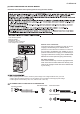
CD-MPX870W CHAPTER 1: GENERAL DESCRIPTION [1] PRECAUTIONS FOR USING LEAD-FREE SOLDER 1. Employing lead-free solder "MAIN, POWER, DISPLAY, GAME INPUT, CD SERVO, LED, CD MOTOR (PWB ONLY), CD CHANGER MOTOR (PWB ONLY) PWB" of this model employs lead-free solder.The LF symbol indicates lead-free solder, and is attached on the PWB and service manuals.The alphabetical character following LF shows the type of lead-free solder. Example: Indicates lead-free solder of tin,silver and copper. 2.
CD-MPX870W [2] SAFETY PRECAUTION FOR SERVICE MANUAL Precaution to be taken when replacing and servicing the Laser Pickup. Laser Diode Properties Material: GaAIAs Wavelength: 795 nm Emission Duration: continuous Laser Output: max. 0.6 mW Note for users in Australia: Copyright may exist in material you wish to record. Copying or broadcasting such material without permission of the relevant in licenses or owners of the copyright is prohibited by law.
CD-MPX870W [5] SPECIFICATIONS FOR A COMPLETE DESCRIPTION OF THE OPERATION OF THIS UNIT, PLEASE REFER TO THE OPERATION MANUAL. As part of our policy of continuous improvement, SHARP reserves the right to make design and specifcation changes for product improvement without prior notice. The performance specifcation figures indicated are nominal values of production units .There maybe some deviations from these values in individual units.
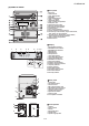
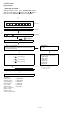
CD-MPX870W [6] NAMES OF PARTS Front panel 1. Disc Trays 2. Timer Indicator 3. Tuner (Band) Button 4. CD Button 5. ON/STAND-BY Button 6. Tape (1 2) Button 7. Game/Video Button 8. Tape 1 Cassette Compartment 9. Headphone Jack 10. Game/ Video Input Jacks 11. Disc Tray Open/Close Button 12. Disc Number Select Buttons 13. Volume Control 14. CD or Tape Stop Button 15. CD Play or Repeat, Tape Play Button 16. CD Track Up or Fast Forward, Tape 2 Fast Forward, Tuner Preset Up, Time Up Button 17.
CD-MPX870W Remote control 1 2 7 8 9 13 17 14 18 15 19 20 10 11 16 22 21 23 3 4 24 25 26 27 28 5 6 12 29 1. Remote Control Transmitter 2. Disc Number Select Buttons 3. Clock/Timer Button 4. Character Input/Disc Direct Search Buttons 5. Equalizer Mode Select Button 6. Extra Bass/Demo Button 7. ON/STAND-BY Button 8. CD Button 9. Tuner (Band) Button 10. Tape (1 2) Button 11. Game/Video Button 12. Volume Up and Down Buttons 13. Disc Clear/Dimmer Button 14. Disc Random Button 15.
CD-MPX870W Service Manual E Market CD-ES700/CD-ES77 CHAPTER 2. ADJUSTMENTS [1] Mechanism section • Driving Force Check Torque Meter Play: TW-2111 • Torque Check Torque Meter Play: TW-2111 Fast forward: TW-2231 • Specified Value Tape 1: Over 80 g Tape 2: Over 80 g Specified Value Tape 1 Tape 2 30 to 80 g.cm 30 to 80 g.cm — 70 to 180 g.cm — 70 to 180 g.cm Tape Speed Test Tape Normal speed MTT-111 Adjusting Point Variable Resistor in motor.
CD-MPX870W [2] Test mode • Setting the test mode During stand-by mode, press GAME/VIDEO button while pressing down the button and button. then, press the CD button to enter the test mode. C D << T E S T IL isn’t done OPEN/CLOSE operation is using manual. IL isn’t done >>,<< IL isn’t done >>buttons make pick's slide possible. A to page 2-3 <> key input. <> key input. Do TOC IL. Do normal play. When these following key is input into PLAY key, track number can be appoint directly.
CD-MPX870W A <> key input. Laser ON. <> key input. Tracking OFF play at that specific point. <> key input. Tracking ON play from that specific point. <> key input. Adjustment result automatically will display as below for each 2 sec : a) "FOF_XXXX" b) "TOF_XXXX" c) "TBAL_XX" d) "TGAN_XX" f) "FGAN_XX" g) "RFLS_XX" <> key input. STOP Sliding the PICKUP with<< must only be in STOP mode.
CD-MPX870W [3] CD section CD Error code description Error 10* 11* 20* 21* 31 Explanation CAM error. Can't detect CAM switch when CAM is moving. When it detect cam operation error during initialize process. TRAY error. Can't detect TRAY switch when TRAY is moving. When it detect TRAY operation error during initialize process. When it change to CD function, DSP cannot read initial data. * 'CHECKING' If Error is detected, 'CHECKING' will be displayed instead of 'ER-CD**'.
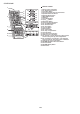
CD-MPX870W [4] CD Changer mechanism section • All numbers in the drawing correspond to those in parts guide (CHANGER MECHANISM PARTS).
CD-MPX870W 2 139 APPLY SANKOL SHS1001 BEFORE FIX FIX ITEM 139 ACCORDING TO THE PICTURE AS SHOWN ABOVE ROTATE MODE BIG GEAR UNTIL REACH AS SHOWN IN PICTURE 2–6
CD-MPX870W 3 143 APPLY GREASE SC141 112 PULL THE LEVER UNITIL REACH THE ARROW MARK 2–7
CD-MPX870W 4 FIGURE 2 FIGURE 1 152 118 142 APPLY GREASE SC141 SLOT CLAMP SWITCH ARM INSIDE BASE SLOT 2–8 HALF GEAR MUST BE ARRANGED AS SHOWN
CD-MPX870W 5 APPLY GREASE SC141 AT BOTTOM SIDE OF GEAR FOLLOW MARKING (REFER TO GRAY AREA) NO NEED TO APPLY GREASE AT BOTTOM SIDE APPLY GREASE SC141 AT TOP SIDE OF GEAR FOLLOW MARKING (REFER TO GRAY AREA) 127 IF DIRECTION IS OTHER THAN DIRECTION SHOWN IN FIGURE 1, IT IS INCORRECT CORRECT 128 INCORRECT FIGURE 1 BLACK MARK 2–9
CD-MPX870W 6 APPLY GREASE SC141 AT HALF GEAR AREA ROTATE CLOCKWISE UNTIL REACH HERE (MAXIMUM) 129 2 – 10
CD-MPX870W 7 149 150 151 2 – 11
CD-MPX870W 8 THE SHOWN AREA MUST FREE FROM GREASE CORRECT GREASE SC141 APPLICATION LENGTH GREASE APPLICATION PORTION INCORRECT 124 131 SHOWN HOLE MUST FACING ARROW DIRECTION 2 – 12
CD-MPX870W 9 APPLY GREASE SC141 AT BOTTOM SIDE ONLY 138 126 TR-RE JOINT GEAR C 125 APPLY GREASE SC141 ONLY AT TOP SIDE GEAR MUST BE FIXED ACCORDINGLY TO THE HOLE'S 2 – 13
CD-MPX870W 10 148 147 146 145 2 – 14
CD-MPX870W 11 121 APPLY GREASE SC141 144 130 WHEN FIXING ITEM 144 MUST FOLLOW AS SHOWN 2 – 15
CD-MPX870W 12 117 FIGURE 1 FIGURE 2 APPLY GREASE SC141 FIGURE 3 2 – 16 APPLY GREASE SC141
CD-MPX870W 13 ITEM 133 , 134 MUST APPLY GREASE SC141 ON TOP SIDE GEAR ONLY 134 133 GEAR 112 CORRECT GEAR 112 INCORRECT 132 TOP VIEW AFTER BEING ASSEMBLED 2 – 17 IT IS INCORRECT TO FIX IT IN REVERSED DIRECTION
CD-MPX870W 14 APPLY GREASE SC141 BEFORE FIX MOVE 112 UNTIL TOUCH THE WALL B A DURING GEAR A ROTATE MUST PRESS SHOWN AREA AND LEVER B WILL MOVE ARROW DIRECTION THEN FIX PART 108 SCREW TORQUE 2 108 +0.
CD-MPX870W 15 APPLY GREASE SC141 113 BEHIND THE LEVER NEED TO APPLY GREASE SC141 PULL IT THEN LEVER WILL MOVE IN 2 – 19
CD-MPX870W 16 123 115 APPLY GREASE SC141 APPLY GREASE SC141 BEFORE FIX APPLY GREASE SC141 AT BOSS SPRING MUST BE ARRANGED UNDER THE HOOK CORRECT LR JOINT LEV BOARD R BOARD R LR JOINT LEV INCORRECT 2 – 20
CD-MPX870W 17 IT IS INCORRECT IF ASSEMBLED IN A REVERSED DIRECTION 103 137 136 APPLY GREASE SC141 BIG SLOT MUST FACING OUT WHEN FIX AND AFTER FIXED TO BASE CHASSIS.
CD-MPX870W 18 IT IS INCORRECT IF ASSEMBLED IN A REVERSED DIRECTION APPLY GREASE SC141 104 135 136 BIG SLOT MUST FACING OUT WHEN FIX AND AFTER FIXED TO BASE CHASSIS AFTER ASSEMBLY, CONFIRM WITH FREE DROP TEST GEAR POSITION DURING FIXING CONFIRM BOTH GEARS SIT PROPERLY AND LOCKED 2 – 22
CD-MPX870W 19 AFTER FIX OUTER UP/DOWN LEVER HOLD AS SHOWN PORTION AND MOVE UP/DOWN THEN CONFIRM WHETHER LEVER GO INSIDE THE HOLE OR NOT 120 137 BIGGER SLOT FACING OUT IT IS CORRECT IF THE LEVER HOLD ENTERS THE HOLE IT IS INCORRECT IF THE LEVER HOLD DOES NOT ENTER THE HOLE 119 135 BIGGER SLOT FACING OUT ALL OF THIS 135 AND 137 GEAR FIX TOGETHER WITH 119 AND 120 LEVER ( MOVE TOGETHER ) 2 – 23
CD-MPX870W 20 BIG SLOT FACING OUT 110 2 – 24
CD-MPX870W 21 PUSH THE LEVER ACCORDING TO ARROW DIRECTION THEN FIX WHEN FIXING MAIN BASE ASSEMBLY FOLLOW ACCORDING TO PICTURE 1 PICTURE 3 PICTURE 1 PICTURE 2 CORRECT MAKE SURE MECHA HOLDER SHAFT FIX PROPERLY TO LEVER 2 – 25 INCORRECT INCORRECT
CD-MPX870W 22 APPLY SANKOL (SHS1001) APPLY SANKOL (SHS1001) ON TOP 101 APPLY SANKOL (SHS1001) INSIDE THE SLOT & OTHER SHOWN PORTION 102 APPLY SANKOL (SHS1001) APPLY SANKOL (SHS1001) AT BACK PORTION APPLY SANKOL (SHS1001) AT TRAY SLIDING PORTION FIX TRAY NO 1 FIRST THAN FOLLOW OTHER 2 – 26 COSMO GUIDE TRAY HAVE MARKING AS SHOWN
CD-MPX870W 23 111 GEAR UP/DOWN BOARD APPLY GREASE SC141 AT INNER & OUTER GEAR SLIDING PORTION WHEN FIX GEAR UP/ DOWN BOARD THE TWO LEVER MUST AT PARALLEL LINE AND POSITIONED AT TOP MAX SIDE AFTER ASSEMBLY GEAR UP/DOWN BOARD 2 – 27
CD-MPX870W 24 SCREW TORQUE 3 +0.
CD-MPX870W 25 AFTER ASSEMBLY TOP PLATE FIX THE FFC FFC4 AFTER PUSH, MAKE SURE SNAP PROPERLY PRESS IN BACK PORTION 122 AFTER FIX, PUSH FOLLOW ARROW DIRECTION 107 BEFORE LOCK SLOT IN AFTER LOCK BEFORE LOCK MUST CONFIRM AFTER LOCK BEFORE LOCK AFTER LOCK MUST CONFIRM 2 – 29
CD-MPX870W 26 CAUTION CORRECT 1. MAKE SURE NO PWB CHIP INSIDE SET .
CD-MPX870W 27 THE TWO SLOT MUST FREE FROM GREASE SC141 APPLY GREASE SC141 BELOW THE MARKING FOR BOTH PORTION ASSEMBLY SEQUENCE 1.
CD-MPX870W 28 MOTOR SCREWING HOLE SCREW TORQUE 1.5 13.8 + 0.2 -0 MUST HAVE GAP M1,2 12.2 +- 0.1 REFERENCE ONLY MOTOR GEAR HEIGHT FROM MAIN BASE 12.2 +- 0.1 + 0.
CD-MPX870W 29 3.1 + 0.
CD-MPX870W 30 BEFORE MELT IT AFTER MELT IT ( MUST FLAT ) WHEN FITTING STABILIZER PLATE TO STABILIZER, ROTATE STABILIZER ANTI CLOCKWISE BY JIG ( STRICTLY CANNOT FIT USING HAND) ( BY HAND CANNOT X ) BELOW 2 – 34 AFTER ASSEMBLED TO HOLDER, STABILIZER NEED TO BE CLEANED WITH ALCOHOL DISC TOUCHING SURFACE
CD-MPX870W 31 106 APPLY GREASE SC141 MUST MAKE SURE SNAP PROPERLY BOTH SIDE ALL SURFACE MUST TOUCH GAP INCORRECT CORRECT 2 – 35 INCORRECT
CD-MPX870W 32 NO GAP HAVE GAP CORRECT INCORRECT 2 – 36
CD-MPX870W CHAPTER 3. MECHANISM BLOCKS CD-ES700/CD-ES77 Market Service Manual E [1] Caution on disassembly Caution on Disassembly Follow the below-mentioned notes when disassembling the unit and reassembling it, to keep it safe and ensure excellent performance: 1. Take cassette tape and compact disc out of the unit. 2. Be sure to remove the power supply plug from the wall outlet before starting to disassemble the unit. 3.
CD-MPX870W (H2)x1 Front Panel (M1)x4 O 3x10mm Tape Mechanism (H1)x6 O 3x10mm (M2)x1 Figure 4 Lug wire Nut (K2)x1 Front Panel Display PWB (K4)x6 O 2.6x10mm Changer Mechanism Unit (K1)x1 Washer (K3)x1 Figure 7 (N1)x4 O 2.
CD-MPX870W STEP 1 REMOVAL Woofer PROCEDURE 1. Front Panel............(A1) x1 FIGURE 9 2. Socket....................(A2) x1 3. Screw.....................(A3) x2 4. Screw.....................(A4) x4 2 Tweeter 1. Screw.....................(B1) x2 3 Super tweeter 1. Screw.....................
CD-MPX870W [2] Removing and reinstalling the main parts 1. TAPE MECHANISM SECTION Perform steps 1 to 5 and 6 of the disassembly method to remove the tape mechanism. 1.1. How to remove the record/playback and erase heads (TAPE 2) (See Fig. 1) 1. When you remove the screws (A1) x 2 pcs., the recording/playback head and three-dimensional head of the erasing head can be removed. Pinch Roller (C1)x1 TAPE 2 Pull Clutch Ass'y Pinch Roller Pawl Figure 3 Record/Playback Head 1.4.
CD-MPX870W 2.1. Remove the pickup. (See Fig. 1) 1. Remove the stop washer (A1) x 1 pc., to remove the gear (A2) x 1 pc. 2. Remove the screws (A3) x 2 pcs., to remove the shaft (A4) x 1 pc. 3. Remove the pickup. Note: After removing the connector for the optical pickup from the connector wrap the conductive aluminium foil around the front end of connector so as to protect the optical pickup from electrostatic damage. (A3)x2 φ2.6x6mm CD Mechanism Reduction gear C Front Rear Figure 3 2.
CD-MPX870W 3.2. How to Remove the tray motor/main cam motor/5-Changer Motor PWB (See Fig. 1) 1. Remove the screws (A1) x 2 pcs., to remove tray motor/main cam motor/5-Changer Motor PWB. Changer Mechanism Unit Main Cam Motor Tray Motor 5-Changer Motor PWB (A1)X2 φ2x10mm Figure 1 NOTE:There are 2 more screws tighten the motors at the bottom of main chassis.
CD-MPX870W CHAPTER 4.
CD-MPX870W [2] Main Block diagrams NC NO USE +B4 11 CHASIS_GND 10 FM_DET 9 TUN_SM 8 R_CH 7 +9V 6 L_CH 5 CHASIS_GND 4 DO 3 CL 2 DI 1 CE TUNER PACK UNIT RTUNSA007AWZZ SPAN SELECTOR NC SW601 CNP303 SPAN Q703~ Q706 Q710 Q711 +B4 SOLENOID DRIVER JK690 GAME INPUT R AUX L JK691 VIDEO OUT 23 L 9 R 16 TAPE L 10 R 15 L 11 TUNER R 14 CD L 12 R 13 VIDEO CNS601 BI601 CNP2 FROM CD SECTION 1 2 3 1 3 4 IC601 LC75341 AUDIO PROCESSOR 7 18 TAPE 1 L-CH P.B. HEAD R-CH REC. P.B.
CD-MPX870W FL701 FL DISPLAY 1 2 50 51 26 ~ 47 8 ~ 25 4 5 TAPE MECHANISM ASS'Y +B8 ~ 79 37 38 39 55 18 VDD 26 57 VDD +B8 40 15 14 27 78 80 VLOAD 81 ~ VDD 41 2 4 34 +B8 CE CLK DI DO RESET AVDD 1 54515253 1011 42 16 17 +B5 SYSTEM MUTE 5 Q901~ Q904 SP RELAY Q905 ON-OFF RL914 11 L-OUT 8 R-OUT 1 M FAN MOTOR DRIVER IC901 STK412-420 POWER AMP. M901 FAN MOTOR SO901 SPEAKER TERMINAL Q906 +B8 SP DET. 2 TO CD SECTION 12 13 20 23 28 29 30 31 D905~D907 6 32 25 36 XL701 4.
CD-MPX870W CHAPTER 5. CIRCUIT DESCRIPTION [1] Waveforms of CD Circuit Stopped CH1=500 mV DC 10:1 CH3=500 mV DC 10:1 T 1 IC1 22 Stopped CH1=200 mV DC 10:1 500 ms/div (500 ms/div) NORM:20 kS/s T 1999/04/07 09:51:15 500 ms/div (500 ms/div) NORM:20 kS/s CH2=500 mV DC 10:1 FDO 1 T FDO 1 IC1 22 2 5 IC1 25 1 TDO 2 IC1 23 3 SPDO CH1 v/DIV 500 mV =Filter= Smoothing : ON BW : FULL =Offset= CH1 : 0.000 V CH2 : 0.0 V CH3 : 0.000 V CH4 : 0.
CD-MPX870W [2] Voltage IC701 PIN VOLTAGE NO 1 4.94 V 4.94 V 2 3 4.92 V 4.92 V 4 1.32 V 5 4.92 V 6 4.92 V 7 8 0.00 V 9 4.87 V 4.87 V 10 4.87 V 11 0.00 V 12 0.00 V 13 0.00 V 14 0.00 V 15 0.00 V 16 0.00 V 17 0.00 V 18 0.00 V 19 20 0.00 V 0.00 V 21 22 4.52 V 23 4.41 V 24 4.54 V 0.00 V 25 0.00 V 26 27 1.87 V 4.05 V 28 4.07 V 29 0.00 V 30 31 4.66 V 32 0.23 V 33 4.95 V 34 4.95 V 35 0.00 V 0.00 V 36 37 13.15 V 13.15 V 38 13.15 V 39 0.00 V 40 41 -23.60 V 42 4.72 V 43 4.41 V 4.54 V 44 45 0.00 V 0.00 V 46 0.00 V 47 0.
CD-MPX870W -MEMO- 5–3
CD-MPX870W CHAPTER 6. CIRCUIT SCHEMATICS AND PARTS LAYOUT [1] Notes on schematic diagram • Resistor: To differentiate the units of resistors, such symbol as K and M are used: the symbol K means 1000 ohm and the symbol M means 1000 kohm and the resistor without any symbol is ohm-type resistor. Besides, the one with “Fusible” is a fuse type. • Capacitor: To indicate the unit of capacitor, a symbol P is used: this symbol P means pico-farad and the unit of the capacitor without such a symbol is microfarad.
CD-MPX870W [3] Schematic diagram Figure 6-2: MAIN SCHEMATIC DIAGRAM (1/2) 6–2
CD-MPX870W Figure 6-3: MAIN SCHEMATIC DIAGRAM (2/8) 6–3
CD-MPX870W Figure 6-4: POWER SCHEMATIC DIAGRAM (3/8) 6–4
CD-MPX870W Figure 6-5: POWER SCHEMATIC DIAGRAM (4/8) 6–5
CD-MPX870W Figure 6-6: DISPLAY SCHEMATIC DIAGRAM (5/8) 6–6
CD-MPX870W Figure 6-7: DISPLAY SCHEMATIC DIAGRAM (6/8) 6–7
CD-MPX870W Figure 6-8: CD SERVO SCHEMATIC DIAGRAM (7/8) 6–8
CD-MPX870W Figure 6-9: CD SERVO SCHEMATIC DIAGRAM (8/8) 6–9
CD-MPX870W [4] Wiring side of PWB Figure 6-10: WIRING SIDE OF MAIN PWB (TOP VIEW) (1/15) 6 – 10
CD-MPX870W Figure 6-11: WIRING SIDE OF MAIN PWB (TOP VIEW) (2/15) 6 – 11
CD-MPX870W Figure 6-12: WIRING SIDE OF MAIN PWB (BOTTOM VIEW) (3/15) 6 – 12
CD-MPX870W Figure 6-13: WIRING SIDE OF MAIN PWB (BOTTOM VIEW) (4/15) 6 – 13
CD-MPX870W -MEMO- 6 – 14
CD-MPX870W Figure 6-14: WIRING SIDE OF POWER PWB (5/15) 6 – 15
CD-MPX870W Figure 6-15: WIRING SIDE OF DISPLAY PWB (TOP VIEW) (6/15) 6 – 16
CD-MPX870W Figure 6-16: WIRING SIDE OF DISPLAY PWB (TOP VIEW) (7/15) 6 – 17
CD-MPX870W Figure 6-17: WIRING SIDE OF DISPLAY PWB (BOTTOM VIEW) (8/15) 6 – 18
CD-MPX870W Figure 6-18: WIRING SIDE OF DISPLAY PWB (BOTTOM VIEW) (9/15) 6 – 19
CD-MPX870W Figure 6-19: WIRING SIDE OF GAME INPUT PWB (TOP VIEW) (10/15) 6 – 20
CD-MPX870W Figure 6-20: WIRING SIDE OF GAME INPUT PWB (BOTTOM VIEW) (11/15) 6 – 21
CD-MPX870W Figure 6-21: WIRING SIDE OF CD SERVO PWB (TOP VIEW) (12/15) 6 – 22
CD-MPX870W Figure 6-22: WIRING SIDE OF CD SERVO PWB (TOP VIEW) (13/15) 6 – 23
CD-MPX870W Figure 6-23: WIRING SIDE OF CD SERVO PWB (BOTTOM VIEW) (14/15) 6 – 24
CD-MPX870W Figure 6-24: WIRING SIDE OF PWB (15/15) 6 – 25
CD-MPX870W CHAPTER 7. FLOWCHART [1] Troubleshooting 1. When the CD does not function The CD section may not operate when the objective lens of the optical pickup is dirty. Clean the objective lens, and check the playback operation. When this section does not operate even after the above step is taken, check the following items. Remove the cabinet and follow the trouble shooting instructions.
CD-MPX870W Stopped CH1=500 mV DC 10:1 (1) Focus-HF system check. CH3=500 mV DC 10:1 T Although a CD is inserted and the cover is closed, "NO DISC" is displayed. 500 ms/div (500 ms/div) NORM:20 kS/s FDO 1 Press the Tray1 CD Eject Button without inserting a disc, and try starting the playback operation. TDO 3 CH1 v/DIV 500 mV =Filter= Smoothing : ON BW : FULL =Offset= CH1 : 0.000 V CH2 : 0.0 V CH3 : 0.000 V CH4 : 0.
CD-MPX870W (2) Tracking system check. Check the TE waveform at pin 16 on IC1. If the waveform shown in Figure 4 appears and soon after NO DISC appears ? No "Initialization" is possible, but play is not possible ? Yes Yes The tracking servo is not activated. Check the peripheral circuits at pins 15, 16 and 23 on IC1, and FFC1. A normal jump operation cannot be completed or the beginning of the track cannot be found. Check the around pin 23 on IC1. No "Initialization" is not possible.
CD-MPX870W (4) PLL system check. Stopped CH1=500 mV DC 10:1 When a disc is loaded, start play operation. CH3=1 V DC 10:1 1999/04/05 17:33:17 CH4=1 V 500 ms/div (500 ms/div) DC 10:1 NORM:20 kS/s PDO0 3 4 The HF waveform is normal, but the TOC data cannot be read. PDO1 T Check the PDOUT waveform. (Figure 6) FDO 1 CH1 v/DIV 500 mV =Filter= Smoothing : ON BW : FULL Check around pins 26~30 on IC1. =Offset= CH1 : 0.000 V CH2 : 0.0 V CH3 : 0.00 V CH4 : 0.
CD-MPX870W CHAPTER 8. OTHERS [1] Function table of IC IC1 VHiLC78690E-1: CD Servo (LC78690E) (1/2) Pin No.
CD-MPX870W IC1 VHiLC78690E-1: CD Servo (LC78690E) (2/2) Pin No. 51 52 Terminal Name CONT1 CONT0 Input/Output Input/Output Input/Output Setting in Reset INPUT INPUT 53 54 55 56 57 58* 59* 60* 61 62 63 64 65 TEST0 STREQ STCK STDATA TEST1 DATA DATACK LRSY VVDD2 VPREF2 VCOC2 VPDOUT2 VVSS2 Input Input/Output Input/Output Input/Output Input Output Output Output — Input Input Output — L INPUT INPUT INPUT L L L L — INPUT INPUT UNSTABLE — 66 67 68 69* 70* 71 72 73 74 75 76 77 DVDD1.
CD-MPX870W VCOC2 VPREF2 VVDD2 VVSS2 VPDOUT2 SLC0 AVDD RCH0 LRVSS LRVDD LCH0 XVDD XIN XOUT XVSS AMUTEB DOUT DVDD DVSS DVDD1.
CD-MPX870W IC2 VHILA6261//-1: Focus/Tracking/Spin/Sled Driver (LA6261) Pin No. 1 2 3 4 5 6 7 8 9 10 11 12* 13 14* 15 16* 17 18 19 20 21 22 23 24 25 26 27 28 29 30 31 32 33 34 35 36 Terminal Name VO3+ VO3VO2+ VO2VO1+ VO1PGND1 REGIN PVCC1 REGOUT VIN1 VIN1G VIN2 VIN2G VIN3 VIN3G VIN4 VIN4G FWD5 REV5 VCONT5 FWD6 REV6 VCONT6 VREFIN SGND SVCC PVCC2 MUTE PGND2 VO6+ VO6VO5+ VO5VO4+ VO4- Function BTL Output pin (+) for channel 3. BTL Output pin (-) for channel 3. BTL Output pin (+) for channel 2.
CD-MPX870W IC2 VHILA6261//-1: Focus/Tracking/Spin/Sled Driver (LA6261) 1 + - + - CH3 36 CH4 35 2 + - + - 3 34 4 33 + - 32 Pre Drive 5 CH2 6 + - 7 8 31 CH5 30 29 Pre Drive + - 9 CH1 28 CH6 + VOLTAGE CONTROL AMP + - BTL 10 22k 11 22k 1k 16 17 18 + DUFFER AMP For 1/2 VCC DUFFER AMP For VREF 11k Reference voltage + 22k 25 24 23 22 21 TSD 1k 11k Mode select 22k 1k 15 + - 11k 13 14 26 + Mode select 12 27 + + - 11k Band gad 1k Figure 8-5 BLOCK DIAGRAM OF I
CD-MPX870W IC601 VHiLC75341/-1: Audio Processor (LC75341) VSS LOUT 5 LBASS 6 LTRE 7 8 9-12 LIN LSEL0 L4-1 RBASS 21 ROUT 22 VREF 23 24 VDD CLK LOUT 3 4 20 LBASS CE LTRE 2 Function Serial data and clock input pin for control. Chip enable pin. Data written into an internal latch in a timing of "H" to "L". Each analog switch is activated. Data transfer enabled at "H" level. Ground pin. Bass band filter comprising capacitor and resistor connection pin and bass/treble output pin.
CD-MPX870W IC851 VHIAN80T53/-1: Multi Regulator (AN80T53) Pin No. 1 2 3 4 5 6 7 Terminal Name Function REG4 Output REG3 Output VCC GND MODE 1 REG2 Output REG1 Output 5.1 V power supply with a minimum peak out current of 1200 mA. 13 V power supply with a minimum peak out current of 1350 mA. Connected to Power supplies. Connected to the IC substrate. REG1, REG2,REG3 and REG4 outputs are turned ON when this pin is 5 V. 10 V power supply with a minimum peak out current of 800 mA. 8.
CD-MPX870W [2] FL Display FL701 VVKNA12MM54-1 GRID ASSIGNMENT 12G 1G MP3 WMA 1a 1a 2a 1a 2a 1a 2a 1a 1a 2a 2a 1a 2a 1a 1a col2 Dot2 2a 2a 1a 2a TOTAL 2a col1 2G 3G 4G 5G 6G 7G 8G 9G 10G 11G D5a D5a D5b D5c a D4a D4a D4b h j k f D4c D3b D3c m e (2G~11G) D1a D1a n d D2c D2b c p r D2a D2a b g D3a D3a (1G) Dot1 D1c D1b ANODE CONNECTION 1G P1 P2 P3 P4 P5 P6 P7 P8 P9 P10 P11 P12 P13 P14 P15 P16 P17 P18 P19 P20 P21 P22 P23 P24 P25 P26 P27 P28 P29 2G 1a 1b 1
CD-MPX870W -MEMO- 8–9
CD-MPX870W PARTS GUIDE MINI COMPONENT SYSTEM MODEL CD-MPX870W CD-MPX870W Mini Component System consisting of CD-MPX870W (main unit) and CP-MPX870 (speaker system). CONTENTS [1] INTEGRATED CIRCUITS [10] CD MECHANISM PARTS [2] TRANSISTORS [11] CHANGER MECHANISM PARTS [3] DIODES [4] VIBRATORS / CRYSTALS [5] TRANSFORMERS [6] COILS [7] CAPACITORS [8] RESISTORS [12] CABINET PARTS [13] SPEAKER BOX PARTS [14] ACCESSORIES / PACKING PARTS [15] P.W.B.
CD-MPX870W NO. PARTS CODE PRICE NEW PART RANK MARK RANK DESCRIPTION [1] INTEGRATED CIRCUITS ! IC1 IC2 IC101 IC503 IC601 IC701 IC851 IC854 IC901 VHILC78690E-1 VHILA6261//-1 VHIAN7345K/-1 VHIKIA4558F-1 VHILC75341/-1 RH-IXA101AWZZ VHIAN80T53/-1 VHIKIA78L05-1 VHISTK41242-1 BE AN AM AF AM AY AL AE BB CD Servo,LC78690 Focus/Tracking/Spin/Sled Driver, LA6261 Playback and Record / Playback Amp.
CD-MPX870W NO.
CD-MPX870W NO.
CD-MPX870W NO.
CD-MPX870W NO.
CD-MPX870W NO.
CD-MPX870W NO.
CD-MPX870W NO.
CD-MPX870W NO.
CD-MPX870W -MEMO- 10
CD-MPX870W [10] CD MECHANISM PARTS 11
CD-MPX870W NO.
CD-MPX870W [11] CHANGER MECHANISM PARTS 13
CD-MPX870W NO.
CD-MPX870W [12] CABINET PARTS 15
CD-MPX870W NO.
CD-MPX870W [13] SPEAKERS BOX PARTS 17
CD-MPX870W NO.
CD-MPX870W 19
CD-MPX870W -MEMO- 22
CD-MPX870W 20