CD-RW5000 SERVICE MANUAL No. S9071CDRW5000 AUDIO TOWER SYSTEM MODEL CD-RW5000 CD-RW5000 Audio Tower System consisting of CD-RW5000 (main unit) and CP-RW5000 (speaker system). • In the interests of user-safety the set should be restored to its original condition and only parts identical to those specified should be used. CONTENTS Page IMPORTANT SERVICE NOTES (FOR U.S.A. ONLY) ...................................................................................................... 2 SPECIFICATIONS .........
CD-RW5000 FOR A COMPLETE DESCRIPTION OF THE OPERATION OF THIS UNIT, PLEASE REFER TO THE OPERATION MANUAL. IMPORTANT SERVICE NOTES (FOR U.S.A. ONLY) BEFORE RETURNING THE AUDIO PRODUCT (Fire & Shock Hazard) Before returning the audio product to the user, perform the following safety checks. 1. Inspect all lead dress to make certain that leads are not pinched or that hardware is not lodged between the chassis and other metal parts in the audio product. 2.
CD-RW5000 CD-RW5000 NAMES OF PARTS ■ Front panel 01. 02. 03. 04. 05. 06. 07. 08. 09. 10. 11. 12. 13. 14. 15. 16. 17. 18. 19. 20. 21. 22. 23. 24. 25. 26. 27. 28. 29. 30. 31. 32. 33. 34. 35. 36. 37. 38. 39.
CD-RW5000 CD-RW5000 ■ Multi-function LCD display ■ Remote control 01. 02. 03. 04. 05. 06. 07. 08. 09. 10. 11. 12. 13. 14. 15. 16. 17. 18. 19. 20. 21. 22. 23. 24. 25. 26. 01. 02. 03. 04. 05. 06. 07.
CD-RW5000 Setting the Clock OPERATION MANUAL 6 Turn the jog dial to adjust the hour and within 2 minutes, press the ENTER button. ● When the 12-hour display is selected, “AM” will change automatically to “PM”. 7 Turn the jog dial to adjust the minutes and within 2 minutes, press the ENTER button. ● The hour will not advance even if minutes advance from “59” to “00”. ● The clock starts from “0” second. (Seconds are not displayed.) The time display will disappear after a few seconds.
CD-RW5000 1 Accessories Accesorios 3 System Connections Conexiones del sistema FM antenna Antena de FM AM loop antenna Antena de cuadro de AM Remote control × 1 Controlador remoto × 1 AM loop antenna × 1 Antena de cuadro de AM × 1 2 Left speaker Altavoz izquierdo FM antenna × 1 Antena de FM × 1 Blue Azul Red Rojo Black Negro Black Negro Speaker wire for MAIN terminals × 2 Cable del altavoz para los terminales MAIN × 2 CD-R × 1 CD-R × 1 Right speaker Altavoz derecho Blue Azul Red Rojo Bla
CD-RW5000 Listening to the Radio Audición de la radio Recording to a Cassette Tape Grabación en una cinta cassette 1 Press the CD button and load the desired disc. 2 Load a cassette into the compartment with side A facing you. Cargue un cassette en el compartimiento con la cara A encarada hacia usted. 3 Press the REV. MODE button to choose one side or both side. Pulse el botón REV. MODE para seleccionar de una cara o ambas caras. Pulse el botón CD y cargue el disco deseado.
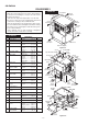
CD-RW5000 DISASSEMBLY CD-RW5000 Caution on Disassembly Follow the below-mentioned notes when disassembling the unit and reassembling it, to keep it safe and ensure excellent performance: 1. Take cassette tape and compact disc out of the unit. 2. Be sure to remove the power supply plug from the wall outlet before starting to disassemble the unit. 3. Take off nylon bands or wire holders where they need to be removed when disassembling the unit.
CD-RW5000 Control PWB Control Panel B (H2)x1 ø3x10mm Speaker PWB (H2)x1 ø3x10mm Power PWB CD-R Unit (G2)x2 ø3x8mm Jog PWB (T1)x5 ø2.6x10mm (V1)x2 ø2.6x10mm (G1)x1 (H1)x1 (V1)x1 ø2.6x10mm Main Chassis (T2)x1 (U1)x5 ø2.
CD-RW5000 CP-RW5000 CD-RW5000 (CD CHANGER MECHANISM UNIT) STEP REMOVAL PROCEDURE FIGURE STEP 8-1 1 1 Top Cabinet 2 Side Panel(Left/Right) 1. Screw ................ (B1) x8 8-1 3 Rear Panel 1. Screw ................ (C1) x3 2. Screw ................ (C2) x10 8-2 4 Front Panel 1. Flat Cable .......... (D1) x1 2. Screw ................ (D2) x4 3. Socket ............... (D3) x6 8-2 5 CD Changer Mechanism 1. Flat Cable .......... (Y1) x1 2. Screw ................ (Y2) x2 3. Screw .........
CD-RW5000 REMOVING AND REINSTALLING THE MAIN PARTS TAPE MECHANISM SECTION Perform steps 1 to 4 and 8 of the disassembly method to remove the tape mechanism. How to remove the record/playback and erase heads (See Fig. 11-1) Erase Head 1. When you remove the screws (A1) x 2 pcs., the recording/ playback head and three-dimensional head of the erasing head can be removesd. Record/ Playback Head (A1)x2 Ø2 x 6mm Figure 11-1 How to remove the pinch roller (Left/Right) (See Fig.
CD-RW5000 FRONT PANEL SECTION Perform steps 1 to 4 of the disassembly method to remove the front panel. How to remove the control panel motor (See Fig. 12-1) (E1)x1 ø2.6x10mm CD Changer Door Panel CD Changer Door Panel 1. Remove the control panel. 2. Remove the screws (E1) x 6 pcs., to remove the CD changer door panel. 3. Remove the screws (F1) x 2 pcs., to remove the control panel motor. (F1)x2 ø2x5mm Gear Box A Control Panel Motor (E1)x2 ø2.6x10mm Motor PWB Gear Box B (E1)x3 ø2.
CD-RW5000 CD CHANGER MECHANISM MAIN BASE PARTS ASSEMBLING/ADJUSTING PROCEDURE Work content Applied part No. 1. Motor assembly (x 2) mounting (screw x 4) Assembly fig. No. 101/129 2. MT idle gear mounting (screw x 1) 125 Fig.14 3. MT system gear assembly 123/124/126/127 Fig.14 4. STB/tray drive system gear and others assembling/ mounting (screw x 3) 137/138/145/146 (153)/147/148 Fig.14 5. Tray big gear assembly 131 Fig.14 6. T.M SW PWB mounting (screw x 3) 7.
CD-RW5000 112 STB DRIVE GEAR R (ASSY) 148 STB GEAR D 103 STB HOLDER 101 MAIN BASE 124 129 129 123 126 110 STB DRIVE GEAR A 123 Mark position 125 127 145 STB GEAR A 153 STB GEAR ANG. 146 STB GEAR B 147 STB GEAR C 110 STB DRIVE GEAR A 111 STB DRIVE GEAR L (ASSY) 137 138 TRAY GEAR C TRAY IDLER GEAR 131 TRAY BIG GEAR After assembling TRAY BIG GEAR, turn it in the arrow direction.
CD-RW5000 124 129 129 123 126 123 125 127 Mark position * This position becomes the reference (stock) position of the tray. 145 132 TRAY GEAR A 146 147 These holes must align. 110 111 Direct the recess part (trapezoidal side) of the axis 135 in this direction. 138 137 131 134 136 TRAY DRIVE GEAR R M T SW PWB TRAY JOINT GEAR R Scale: 2 magnifications *2 133 TRAY GEAR B Scale: 2 magnifications It must not rotate in contact with the peripheral (hatched) part of 131.
CD-RW5000 Mark position (Assemble the mode big gear in this position.
CD-RW5000 37° Mark position 128 142 LIFT GEAR A 132 133 145 130 TRAY DRIVE GEAR F 146 110 147 111 141 143 TRAY JOINT GEAR F (CHANGE BOX L ASS'Y) ASSEMBLING POSITION LIFT CAM 144 140 LIFT CAM Scale: 2 magnifications Assembling procedure 1. Turn the mode big gear approx. 37 degrees in the arrow direction. 2. Assemble the change box L ass'y. Note: At this time, the tray joint gear F must be located in the position shown in figure. Moreover, the gear must be engaged securely. 3.
CD-RW5000 180 TOP PLATE F 37° Mark position 142 LIFT GEAR A 132 133 145 130 146 110 147 135 111 141 143 140 144 STB HOLDER HEIGHT ADJUSTING METHOD When the height of STB holder is high, (Decrease the clearance.) When the height of STB holder is low, (Increase the clearance.) Bend this part. 240 OS LEVER Adjusting procedure 1. Turn the mode big gear approx. 37 degrees in the arrow direction. 2.
CD-RW5000 Mark position Be sure to assemble the tray into this position. 191~196 TRAY1~TRAY6 Insert it along the guide of the change box. 142 LIFT GEAR A 132 133 145 ,,,, ,,,, ,,,, 146 110 147 130 TRAY No.1~6 111 141 143 140 144 Tray installing method: (After adjusting the height of the STB holder) Rear side Rear surface: Stamped. Note: During insertion, Do not accidentally rearrange tray numbers. 135 ,, ,, ,, 1.
CD-RW5000 ADJUSTMENT MECHANISM SECTION MAIN PWB • Driving Force Check Torque Meter AM Tracking Specified Value Play: TW-2412 Over 80 g BF301 Torque Meter Play: TW-2111 30 to 60 g. cm Fast forward: TW-2231 60 to 120 g.
CD-RW5000 TEST MODE Outline While the unit is turned off, press the POWER key while holding down the VOLUME-DOWN and PANEL OP/CL keys to enter the test mode selection mode. Then, the unit is started, the panel is opened, and the microcomputer's version/destination/span is displayed. If the following data is entered from the keyboard while in the test mode selection mode, the unit directly enters the specified test mode. This operation is applied to the main unit's keys only.
CD-RW5000 2. Soft reset Purpose: To initialize the unit. Function: To initialize all functions. Operation: "ALL CLEAR" is displayed, all functions are initialized, and the unit is turned on. To exit the test mode When the initialization through soft reset is complete, the unit is turned on. Table Character display for test mode 2 Character display Item Reset operation display Type Auxiliary display Operation 1 2 3 4 A L L 5 6 7 8 : 9 10 11 12 C L E A R Auxiliary display Note 3.
CD-RW5000 (3) Step 3 mode Performs focus search and turns on the focus servo. Focus search is repeated until it is brought into focus. Display "T3___________0:00" The keys you can press here and the resulting operations are as follows: "POWER" ........... The test mode is turned off, the power is turned off, and the unit is placed in the normal standby mode. "FF/FWD" ........... While holding down this key, the pickup is moved outward. "REW/REV" ........
CD-RW5000 Table 24. TEST-TuSet preset frequencies CH 1% 2 3 4 5 6% 7 8 9 10 11-40 BAND U.S.A. FM FM 87.5 MHz FM108.0 MHz FM 90.0 MHz FM106.0 MHz FM 98.0 MHz AM AM 530 kHz AM1720 kHz AM 600 kHz AM1400 kHz AM 990 kHz Unused channels are indicated with "_". '%' indicates the last channel for each band. All FM bands are preset to FM monaural.
CD-RW5000 NOTES ON SCHEMATIC DIAGRAM • Resistor: To differentiate the units of resistors, such symbol as K and M are used: the symbol K means 1000 ohm and the symbol M means 1000 kohm and the resistor without any symbol is ohm-type resistor. Besides, the one with “Fusible” is a fuse type. • Capacitor: To indicate the unit of capacitor, a symbol P is used: this symbol P means pico-farad and the unit of the capacitor without such a symbol is microfarad.
CD-RW5000 V SWITCHING Q351 TUN_L 13 MO/ST 14 L-CH OUT (FM/AM) 12 PHASE TUN_R 15 R-CH OUT X351 456kHz IC303 LA1832S FM IF DET./FM MPX.
CD-RW5000 l Q507 REC_R-CH k j Q508 8 4 7 VSM 1 – 2 3 + + – 5 6 C2B_DO C2B_CL C2B_DI C2B_CE REC_L-CH +B -B REC_L-CH IC501 BU4066BCF INPUT SELECTOR IC503 NJM4558M OPE AMP.
CD-RW5000 UNA901 DIGITAL INPUT CNP975 FROM CD PWB EBU GROUND EBU SIGNAL(INPUT) SCREEN EBU GROUND EBU SIGNAL(OUTPUT) SCREEN IC926 TC7WU04F INVERTOR CNP912 GROUND(CASE) GROUND(CASE) RESET REQKBE +B I2C-CLOCK GROUND(D) +B I2C-DATA 7 8 UNA902 DIGITAL OUTPUT +B CST_SW CASSETTE SWITCH F_REC R_REC 12 12 1 11 12 CAM SW B-FP SW TUNER CL CE CST SW DEST_IN SPAN CD MUTE CLK DATA LCK1 LCK2 LCD DB4 TEST/Vpp +B Q905 FFC970 11 KEY 4 SOLENOID DRIVER 1 10 1 2 10 9 8 7 6 5 4 3 2 12 1 SOL
CD-RW5000 DIG_SEL IC912 BU2092F OUTPUT EXPANDER +B +B +B IC702 OUTPUT EXPANDER BU2092F 13 Q8 12 Q7 11 Q6 10 Q5 +B CD PICK IN 94 CD RW 93 CD RESET 92 FH A-SW A FH A-SW B SW750~SW758 SW760~SW769 LED_6 SW783, SW772~SW778 JOG701 JOG DIAL 83 CNP931 +B 1 A_+B +B 2 D_+B 3 D_GND 4 REMOCON 5 POW_KEY 6 POW_IND 7 DATA 8 CK 9 LCK 10 KEY1 11 KEY0 82 81 D_+B 69 70 71 72 73 74 75 76 77 78 79 80 IC922 BA3835F BAND PASS FILTER 1 2 3 4 5 6 7 8 9 IC913 KIA7805P VOLTAGE REGULATOR +B 1 IC913 LED770 +B C
CD-RW5000 Q200 MO200 FAN MOTOR + Q212 JK701 HEADPHONES FAN MOTOR DRIVER M SO201 + Q210 + RY202 + + SP L-CH GND MAIN SP L-CH SP L-CH SO201 GND SPEAKER SP L-CH SUB TERMINALS WOOFER SP R-CH GND SP R-CH AC POWER SUPPLY CORD AC 120V, 60Hz SP R-CH GND MAIN SP R-CH L802 LINE FILTER RY801 F807 5A 125V Q209 RY201 T801 MAIN POWER TRANSFOMER T802 SUB POWER TRANSFORMER M+10V Q211 TF Q208 15 D806 D805 D814 D815 D813 2 1 D812 F801 2.5A 125V D807 -B D804 F808 2.
CD/CD-RW_SEL IC2 TC9490F SERVO/SIGNAL CONTROL TO MAIN PWB – 31 – PDO PVDD /UHSO /HSO SBSY SFSY DATA CLCK SBOK DVSS DVDD IPF DOUT AOUT LRCK BCK Figure 31 BLOCK DIAGRAM (6/6) NC TRAY SWITCH CNP1 1 2 CNS12 CNP975 TO MAIN PWB SWB101 SWB102 SWB103 IC6 +B C F B A E VREF +5V SWITCHING IC6 TA2147F SERVO PRE AMP.
CD-RW5000 +B C321 100/16 C345 0.022 C346 0.022 0.8V 0.1V 1.8V Q302 KTC3194 Y OSC BUFF C318 100P(CH) T311 T312 FM IF C2B_DO R371 4.7V R373 1K R399 10K 0V D 4.7V 4.7K Q371 KTA1266 GR SWITCHING R374 1K C311 100P(CH) C312 100P (CH) C382 15P(CH) C310 100P (CH) R372 1K +B C337 0.022 D352 DS1SS133 VDD 17 L351 100µH 9.2V 11 ST IND IF IN 12 0V R378 82K R360 4.7K 3 CF302 FM IF 10.7MHz R323 68K +B R351 5.6K C351 0.022 L353 1mH C352 10/50 2V 1 FM IF IN AM OSC OUT 24 3V 4.6V 4.
CD-RW5000 R547 2.2K R548 2.2K C573 2.2/50 R591 47K R592 47K 8 11 – C446 22/50 R414 (6V) (-6V) (-6V) RECORD SIGNAL R420 C449 330 0.1 R413 47K 47K Y AUX_SEL X VSM W C2B_DO V C2B_CE U C2B_DI T C2B_CL S D_GND R S-MUTE Q CD-R_SEL O PB_MUTE (0V) S-MUTE +B R544 47K C529 10/50 C510 10/50 C512 0.1 (ML) 5V C514 0.1(ML) 10V C516 0.0027(ML) 5V R532 R534 5V 3.9K 3.9K C518 1/50 5V C520 1/50 AUX_R 5V C522 1/50 TAPE_R 5V C524 1/50 TUNER_R 5V C526 CD/CD-R_R 1/50 5V C528 1/50 R526 1K R528 2.2K R530 3.
CD-RW5000 MAIN PWB-A (3/3) C 1 (C C950 150P (CH) EX-DATA R1031 1K EX-CLK R1007 1K R1008 1K LCK1 FM SIGNAL A PLAYBACK SIGNAL R1141 1K RECORD SIGNAL CD SIGNAL +B +B SPAN SEL. R1101 R1102 R1103 R1104 R1022 R1124 10K R 10 R1106 R1107 R1108 R1109 22K 22K 22K 10K 47K R1068 10K 10K 10K 10K 10K +B B L901 100µH 33 R1046 12K IC905 KIA7042AP RESET 3 IC905 1 5V 5V Q901 KRC102 M C905 5V 3.3/50 2 4.4V 3 2 0V C904 0.01 F R1143 1M D907 DS1SS133 0V 1 C903 0.1/50 C906 0.
CD-RW5000 CNP975 C957 150P (CH) IC912 BU2092F OUTPUT EXPANDER C970 5V +B VSS VDD 18 0V 0.1 DATA OE 17 0V R1032 1K DIG_SEL CLK SW12 16 0V R1052 1K AUX_SEL LCK SW11 15 2.8V R1051 1K FAN CD-SW SW10 14 0V R1050 1K PNL_OP NC SW9 13 0V R1023 1K PNL_CL NC SW8 12 R1020 NC SW7 11 P_CONT 1K CD-R_SEL SW5 10 0V 0V 0V 0V 1.1V 1 2 3 4 5 6 7 8 0V 9 R1141 1K IC912 BU2092F LCD_RESET C971 0.1 R1024 10K (2.6V) R1026 10K (5V) (2.4V) (2.4V) (5V) (2.6V) (0V) (5V) IC921Vcc 14 1 2 3 4 5 6 7 GND (0.5V) 13 (0.
CD-RW5000 DISPLAY PWB-B1 LED735 LNG995PF LED738 HLMP1700 A BI705B BI705A +B LED737 1 LNG995PF 2 R789 150 R790 330 1 +B +B 2 LED A PWB-B2 (10V) Q706 KTC3199 GR (6.2V) (5.7V) CNP703 B 1 R788 82 1 VLOUT 2 3 4 5 6 VCC (5V) 7 GND (0V) 8 /RD (4.7V) 9 /WR (4.6V) 10 RS (4.5V) 11 /CS (0V) 12 (5V) 13 /RESET DB4 (0.8V) 14 DB5 (2.7V) 15 DB6 (2.7V) 16 DB7 (1.6V) R717 3.3K R798 33K C701 0.022 Q707 0.8V KTC3203 Y 0.2V R716 22K LCD710 LCD DISPLAY C C716 2.
CD-RW5000 BI740B BI740A MOTOR PWB-B7 1 2 3 1 2 3 SW705 OPEN/CLOSE CNS741 BI741 1 2 3 4 5 TO MAIN PWB CNP933 P35 12-H 1 2 3 4 5 OPEN_SW CLOSE_SW D_GND MOTOR_+ MOTOR_– SWITCH PWB-B8 + – C715 0.1 M MO700 CONTROL PANEL MOTOR FM SIGNAL HEADPHONES PWB-B9 TO POWER PWB CNS730 BI730 1 2 3 4 CNP207 P41 12-B 1 2 3 4 JK701 HEADPHONES RA711 150 L705 2.
CD-RW5000 CNS911A CNS911B 1 2 3 4 5 6 1 2 3 4 5 6 CNP911 P35 12-B A 1 TO MAIN PWB 1 CNP914 P35 12-C FFC914 5 5 1 1 CNP912 P35 12-C FFC912 7 B 7 1 2 3 4 5 6 7 TO POWER PWB CNP808 P40 1-E CD SIGNAL 1 2 3 4 5 6 7 CNS808A 1 2 3 4 5 6 EBU GROUND EBU SIGNAL(INPUT) SCREEN EBU GROUND EBU SIGNAL(OUTPUT) SCREEN 1 2 3 4 5 A-OUT(PB)L-CH A-OUT(PB)R-CH A-IN(REC)R-CH GROUND(A) A-IN(REC)L-CH 1 2 3 4 5 6 7 12C-DATA GROUND(D) 12C-CLOCK REQKBE RESET GROUND(CASE) GROUND(CASE) 1 2 3 4 5 6 7 –8V +12V GN
CD-RW5000 C95 100P C94 100P C93 100P GND(D) CANA_A CANA_B CANA_C CANA_D CANA_E CANB_A CANB_B CNP2 1 2 3 4 5 6 7 8 GND(D) CAMA_A CAMA_B CAMA_C CAMA_D CAMA_E CAMB_A CAMB_B C99 100P C96 100P C58 100P C59 100P C60 100P 0.3V SWITCHING C45 C48 470/10 100/10 C49 0.1 2.3V Q1 2SC1740 R R35 1K R36 2.2K R37 33K 10 BIAS R52 560 8 IC6 TA2147F SERVO PRE AMP. 2.7V 1 2 3 4 5 6 7 8 Q4 KTA1266 GR C67 0.
4.6V R225 10K 4.6V 0V Ch1 Out 31V R215 22K R248 56K R256 FR252 0.1(1W) 100 R260 Fusible C240 1K 0.022 4.6V R258 10K 0V 0V Q204 KTC3199 GR R250 1K R246 820 C234 1/50 0V 8 C242 C236 15P +V 6 7 0V -30V 30V 5 C238 100/50 4 NC -0.2V C232 -0.2V 220P 0V 3 + C251 R278 47/50 56K Q201 KTC3199 GR -B R201 1K Q206 KTC3199 GR 4.6V 0V R244 1K R262 56K R261 56K 0V Q205 KTC3199 GR D201 DS1SS133 R209 C205 1K 15P -0.2V R203 820 0V -0.2V -36V R229 0V 0.
CD-RW5000 + 14 +B 0V 0V 0V R281 12(1/2W) +B R284 1K C257 10/50 R267 330(1/2W) +B R274 22K R213 100 R273 22K R275 22K RY202 R270 330(1/2W) R279 22K C253 3300/63 C252 2200/50 DRIVER P37 8-C CNS730 FROM HEADPHONES PWB SO201 SP L-CH MAIN GND + SP L-CH SO201 SP L-CH SPEAKER GND + SP L-CH SUB TERMINALS SP R-CH WOOFER GND + SP R-CH SP R-CH MAIN GND + SP R-CH - - BI201B BI201A C245 0.1(ML) R271 4.7(1/2W) 1 2 3 4 5 6 7 8 1 2 3 4 5 6 7 8 BI808 FM SIGNAL C833 0.047(ML) C834 F806 0.
CD-RW5000 FROM CNS940 P35 9-H MAIN PWB P40 1-F TO POWER SECTION CNP102 TAPE_L-CH TAPE_R-CH A_GND REC_R-CH REC_L-CH REC_MUTE REC_CONT REC_BIAS +B C134 47/25 BIAS OSC. Q116 KTC3203 Y 0V 1 C141 1/50 1 GND 12 11.3V R148 4.7 C133 0.039(ML) C137 0.0082 R143 82 R141 R139 C135 22K 0.047(ML) 47K Q114 SWITCHING 2SA1015 GR 6.8V 13 Vcc L104 330µH 0V 0V C131 4V 0V 14 RIPPLE ALC 11 22/50 0V C130 1/50 C138 0.0033 R109 15K C124 0.022 16 R134 100 R132 1.5K C122 270P R130 R150 1K 6.
CD-RW5000 LCD710 RD WH LED A PWB-B2 1 2 R790 BI705B LED735 LED738 LED737 R789 COLOR TABLE BR BROWN RD(R) RED OR ORANGE YL YELLOW GR GREEN BL BLUE VL VIOLET GRAY GY WH(W) WHITE BLACK BK PINK PK 1 17 DISPLAY PWB-B1 C717 16 14 12 10 8 6 4 2 C701 17 15 13 11 9 7 5 3 1 C716 CNP703 R798 R794 R795 R796 R797 R793 R717 CNS702 12 BI702 RD BL BL BL BL BL BL BL BL BL BL BL L702 R731 1 R730 B C E L701 R716 CNP935 Q706 P46 1-A TO MAIN PWB C706 C705 BI705A 1 C704 E C B Q707 2 R748 TO
CD-RW5000 P47 11-H CNP911 TO MAIN PWB A TO POWER PWB P51 12-F CNP808 RD CNP914 CNP912 765 4 321 BK WH RD BK WH RD 1 123 4 56 7 1 CNS808B R707 5 FFC912 SW720 CD1 EJECT CNS911B R708 FFC914 R701 3 2 1 GY WH GY WH GY WH RD SW730 CD1 PLAY R726 B TO MAIN PWB P46 2-H LED759 SW701 POWER Q725 TO MAIN PWB P46 3-H CNS808A CD SWITCH PWB-B3 WH BK WH RD BK 6 5 4 3 2 1 CNS911A 765 4 321 RX701 TO MAIN PWB 3 2 3 2 3 Q723 Q724 R750 1 R703 LED757 1 SW732 CD3 PLAY C707 C703 R74
CD-RW5000 JOG PWB-B5 CONTROL PWB-B4 SW758 PLAY SW757 STOP R781 R777 R779 SW756 PLAY/ PAUSE R783 LED722 LED783 R769 SW753 FAST REVERSE SW751 ERASE SW769 HIGH/ NORMAL SW775 MENU R775 R785 R778 R766 SW772 EQUALIZER MODE SW783 PLAY MODE R782 R770 R774 SW773 X-BASS SW761 TAPE SW762 TUNER SW760 AUX R754 Q708 R767 R776 R772 R787 R780 R753 C712 1 6 R757 R760 C713 3 2 1 BI773 R761 1 4 7 1 1 4 BI770 BI771B 2 1 CNS772 GY WH GY WH GY WH RD CNS773 1 2 WH GY WH RD RD
CD-RW5000 TO TAPE MECHANISM PWB P43 11-F FROM JOG PWB P45 11-E CNS770 FROM DISPLAY PWB P43 12-E CNS701 FROM CD SWITCH PWB P44 1-D CNS720 A FROM MOTOR PWB P45 8-F CNP741 TO POWER PWB P51 12-E CNP807 FFC970 1 12 8 7 6 5 4 3 2 1 BI950 C913 Q905 B 3 C901 R1051 C714 7 6 5 4 R763 18 10 3 2 1 R1027 R762 1 2 3 4 5 6 7 8 9 10 11 12 R915 H 1 2 R908 R906 R905 R982 R501 Q509 R902 R977 C R916 C1003 R997 R928 CNP901 32 30 28 26 24 22 20 18 16 14 12 10 8 6 4 7 5 3 R1090 R1089 R1088
CD-RW5000 R376 D304 D303 D302 D301 C304 C303 L312 C308 C309 R313 C317 C316 D306 D305 C397 D311 D312 C301 C384 C389 R550 R548 C540 BLUE VL VIOLET GY GRAY WH(W) WHITE BK BLACK PK PINK L-CH JK501 C448 PHONO INPUT UNA901 C400 1 2 3 UNA901 DIGITAL INPUT UNA902 C973 C974 1 2 3 C976 C975 L911 10 R-CH C599 R402 R404 R408 C438 C411 R409 C439 UNA902 DIGITAL OUTPUT 5 1 CNP975 2 1 C978 C1009 2 4 8 5 1 4 IC926 1 3 5 6 CNP911 WH GY WH GY WH GY WH RD 1
CD-RW5000 TO MAIN PWB CNP901 P46 6-H FFC901 1 CD PWB-C 33 C49 CNP1 DZ2 E C92 C37 R38 C46 TP10 IC5 R77 R78 R49 TE R50 R43 R44 24 CNP5 IC6 R52 L7 10 C47 5 20 R40 Q4 B C E 12 R53 1 1 2 3 4 5 6 7 8 C32 Q1 C44 R48 R55 C43 R56 CNP7 B C E C58 C33 C60 C98 15 C40 R37 R35 C45 1 13 R39 R36 C36 C30 R27 C67 TP14 C42 C41 C23 TP6 3 2 14 15 4 11 32 R54 R31 C25 R32 C20 R47 C99 C95 C96 F C97 C29 R29 C26 C24 R25 R30 C94 1 2 3 4 5 6 7 8 CNP2 FE R
CD-RW5000 MOB2 TRAY MOTOR MOB1 MAIN CAM MOTOR CNS4 YL 4 OR 3 RD 2 BR 1 NM2 SLED MOTOR + CNS6B BL GY GY GY GY GY 1 2 3 4 5 6 1 2 3 4 5 6 NM1 SPINDLE MOTOR CNP6A 1 2 3 4 5 6 - CNS6A NSW1 PICKUP IN + CD MOTOR PWB-E CNS5A 1 2 3 4 5 6 7 8 CNS5B RD GY GY GY GY GY GY GY CNS7A 1 2 3 4 5 6 7 PICKUP UNIT 1 2 3 4 5 6 7 8 CNS7B RD WH WH WH WH WH WH 1 2 3 4 5 6 7 7 6 5 4 3 2 1 COLOR TABLE 8 7 6 5 4 3 2 1 8 BR FW2 8 SWB110 TRAY2 SWB109 TRAY1 1 BROWN RD(R) RED OR ORANGE YL YELLOW GR G
CD-RW5000 SO201 SPEAKER TERMINALS MAIN SUB WOOFER MAIN R-CH GND R-CH GND L-CH GND L-CH GND A SPEAKER PWB-D3 L201 L204 L202 B BI201B 1 L203 WH GY WH GY WH GY WH RD 8 AC POWER SUPPLY CORD AC 120V, 60Hz GY WH GY WH RD BK WH C CNS808 5 4 3 2 1 BL 1 RD 2 D CNP801 1 L802 LINE FILTER 2 RD WH GY WH GY T801 MAIN POWER TRANSFORMER RD BL BK BL RD BL RD 1 E 1 2 3 4 5 5 F806 4A 125V OR C836 C834 BI808 T802 SUB POWER TRANSFORMER OR YL BK YL F807 5A 125V 5 4 3 2 1 D816 R827 C833
CD-RW5000 POWER PWB-D1 C807 R811 R837 R822 C810 R806 LED801 C231 15 R234 C221 C226 C225 R237 C249 R233 R228 1 2 3 4 C247 IC203 C248 C207 8 7 6 5 R221 R235 C213 R277 C229 C219 R217 D205 R813 C820 C803 8 R144 R134 CNP808 R200 DZ201 1 2 3 4 5 6 7 CNP204 1 2 C141 Q120 3 1 2 10 Figure 51 WIRING SIDE OF P.W.
CD-RW5000 WAVEFORMS OF CD CIRCUIT STOP NO DISC FOCUS SEARCH 1 PLAY FOO IC2 33pin 12 2 IC5 2pin 3 TMAX IC2 17pin FO+ 13 SBOK IC2 8pin FO- IC5 1pin 14 DMO IC2 41pin 0.2µs FOCUS SEARCH 0.2µs STOP TOC IL 6 4 TEI IC2 31pin SEL IC2 38pin 5 PLAY 11 TRO IC2 34pin FEI IC2 29pin 6 15 TEI FMO IC2 40pin IC2 31pin 0.2µs 0.2µs STOP 5 PLAY CUE 6 FEI IC2 29pin 7 11 SBAD TRO IC2 34pin IC2 30pin 8 TEI IC2 31pin RFO IC6 22pin 15 FMO IC2 40pin 0.2µs STOP 5 0.
CD-RW5000 TROUBLESHOOTING When the CD does not function When the CD section does not operate when the objective lens of the optical pickup is dirty, this section may not operate. Clean the objective lens, and check the playback operation. When this section does not operate even after the above step is taken, check the following items. Remove the cabinet and follow the troubleshooting instructions.
CD-RW5000 Check in the CD test mode. STEP 1 Does the display "E-CD01" appear? Yes No Does the pickup move to the inner/outer position using the 'UP'/'DOWN' key? Check the line of PU-IN SW. Check from pin 2 of CNP6 via pin 25 of CNP1 to pin 94 of IC901. No Check the line of the slide control. Check from pins 3 and 4 of CNP6 via pins 17, 18 and 22 of IC5 to pin 40 of IC2. No Check from pins 7 and 8 of CNP5 via Q4 and pins 6 and 7 of IC6 to pin 38 of IC2.
CD-RW5000 Troubleshooting for CD-R unit Check the items 1, 2 and 3. If the playback/recording operation is not possible, the CD-R unit is defective. When no sound is heard during playback, check the item 4. If there are no output signals, CD-R unit is defective. 1. Check of supply voltage -8V Pin 1 of CNP808 +12V Pin 2 of CNP808 +5V Pins 6 and 7 of CNP808 Stopped CH1=5V CH2=5V CH3=5V DC P*10 DC P*10 DC P*10 27-JUL-00 09 58 50 µs/d 2. Check of control signal from the system microcomputer 1.
CD-RW5000 FUNCTION TABLE OF IC IC2 VHiTC9490F/-1: Servo/Signal Control (TC9490F) (1/2) Pin No. Function Terminal Name Input/Output 1 BCK Output Bit clock output terminal. 32fs, 48fs or 64fs can be selected by command. 2 LRCK Output L/R channel clock output terminal. L channel: "L", R channel: "H". the output polarity can be inverted by command. 3 AOUT Output Audio data output terminal. MSB/LSB fast can be selected by command. 4* DOUT Output Digital out output terminal.
CD-RW5000 IC2 VHiTC9490F/-1: Servo/Signal Control (TC9490F) (2/2) Pin No. Function Terminal Name Input/Output 39 AVDD3 40 FMO Output — Analog 3.3V power supply terminal. Feed equalizer output terminal. 41 DMO Output Disc equalizer output terminal. 42 VSS3 — Digital GND terminal. 43 VDD3 — Digital 3.3V power supply terminal. 44 TESIN Input 45 XVSS3 — 46 XI Input 47 XO Output 48 XVDD3 49 DVSS3 50 RO 51 DVDD3 52 DVR 53 LO 54 DVSS3 Test input terminal.
CD-RW5000 IC6 VHiTA2147F/-1:Servo Pre Amp. (TA2147F) Pin No. Terminal Name Function Input/Output 1 VCC — 2 FNI Input 3.
CD-RW5000 IC901 RH-iX0355AWZZ: System Microcomputer (IX0355AW) (1/2) Port Name Pin No.
CD-RW5000 IC901 RH-iX0355AWZZ: System Microcomputer (IX0355AW) (2/2) Pin No.
CD-RW5000 IC702 VHiBU2092F/-1: Output Expander (BU2092F) Pin No.
CD-RW5000 DB4-DB7 /RESET RS /CS /RD /WR GND VC1 VCC C2- C1- C1+ VLOUT C2+ LCD DISPLAY LCD710: RUNTZ0021AWZZ 60 3 4+COMS LCD (12 characters 3 lines) with lcons 7 Pin No. Pin Name 7+COMS I/O Connect to 1 VLOUT O Booster capacitance Potential difference between VCI and GND is boosted twice and then output. Magnitude of boost is selected by instruction. Description 2, 3 C1-, C1+ — Booster capacitance External capacitance should be connected here.
CD-RW5000 PARTS GUIDE AUDIO TOWER SYSTEM MODEL CD-RW5000 CD-RW5000 Audio Tower System consisting of CD-RW5000 (main unit) and CP-RW5000 (speaker system). “HOW TO ORDER REPLACEMENT PARTS” To have your order filled promptly and correctly, please furnish the following information. 1. MODEL NUMBER 2. REF. No. 3. PART NO. 4. DESCRIPTION For U.S.A. only Contact your nearest SHARP Parts Distributor to order.
CD-RW5000 NO. PRICE RANK PARTS CODE DESCRIPTION NO.
CD-RW5000 NO. PRICE RANK PARTS CODE DESCRIPTION NO. VARIABLE CAPACITORS VD301 VD302,303 VHCSVC348S/-1 VHCSVC211C/-1 J J AK Variable Capacitance,SVC348S AG Variable Capacitance,SVC211C J J J J J AF AF AH AE AC Crystal,16.934 MHz Crystal,456 kHz Crystal,4.5 MHz Ceramic,8 MHz Crystal,32.
CD-RW5000 NO.
CD-RW5000 NO.
CD-RW5000 NO.
CD-RW5000 NO.
CD-RW5000 NO. PRICE RANK PARTS CODE DESCRIPTION NO.
CD-RW5000 NO.
CD-RW5000 CD-RW5000 306-2 A 306 306-1 306-3 701 704 B 701 304 C 302 301 702 D 303 703x2 E NM1 F 307 NM2 308 305x2 G NSW1 H PWB-E 1 2 3 4 Figure 9 CD MECHANISM EXPLODED VIEW –9– 5 6
CD-RW5000 CD-RW5000 803x3 803x2 114 117 803x2 A 803x3 806 148 B 802x3 116 126 803x2 802x2 107 152 147 806 PWB-F 145 C 149 118x2 146 106x6 124 115 125 134 143 102 803 144 803 138 123 127 142 120 130 D 141 807 132 805 140 137 805 141 804 133-1 139 131 121 119 133-2 803x2 E 133 804 119 113 136 121 128 129 135 F 122 805 112 123 111 PWB-G 133-3 151 101 104 110 105 G 109 801x4 MOB1 PWB-C MOB2 803x2 803x3 802x2 808x4 803 108 H 805x4 CD MECHANISM
CD-RW5000 CD-RW5000 A 1-6 B 1-5 1-1 1-2 1-4 C D 1 1-3 E F G H 1 2 3 4 Figure 11 CD-R UNIT SERVICE PARTS EXPLODED VIEW – 11 – 5 6
CD-RW5000 CD-RW5000 201-3 201 A 201-4 208 PWB-B1 603x4 609x4 201-46 B 201-25 201-31 201-38 223 BELT CONNECTION 201-37 LCD710 FF/REW FF/REW Clutch Belt PWB-B2 Tape Motor 602 201-23 201-34 TAPE MECHANISM 608 C 201-43 220 612x4 Flywheel PWB-B10 201-1 608 201-44 201-40 201-41 201-39 x2 201-16 PWB-B3 250 250-1, 250-2, 250-3, 250-4, 250-5, 250-6, 250-7, 250-8, 250-9 201-42 201-36 619 201-35 608 201-18 608x2 201-24 201-22 201-21 610x2 201-14 PWB-B9 201-17 201-27 201-12 201-1
CD-RW5000 CD-RW5000 617 618x2 A Q809 IC802 Q805 Q801 236 617x5 Silicon Grease 615x4 204 618x2 605 PWB-D1 615 239 232 222 219 614 B 216 605 617x2 PWB-D3 615 IC801 207 IC202 221 Q806 Silicon Grease IC201 615 617x8 231 616x4 Silicon Grease C 230 617x4 617 615x3 604x4 M0200 238 228 614x2 D 202-2 202-1 227 225 226 241 210 202 211 620x2 PWB-D2 614 T801 215 209 240x16 PWB-A 614 238 228 601x2 616x2 614 E 614x3 212 220 237 242 213 614x4 605x4 217 F 203-1 619
CD-RW5000 CP-RW5000 A 703 702 710 709 718x4 708 B 701 C SP605(L-CH) SP606(R-CH) SP603(L-CH) SP604(R-CH) 715x2 D 704 713 712 720x2 706x2 716x2 719 714 711 E 717x4 719 707x2 705 F TWEETER SP603(L-CH) SP604(R-CH) SP601(L-CH) SP602(R-CH) WOOFER Capacitor SP601(L-CH) SP602(R-CH) BK YL BK TWEETER SP603(L-CH) SP604(R-CH) G Capacitor 2.7µF,100V Electrolytic (N.P.
CD-RW5000 PACKING OF THE SET (FOR U.S.A. ONLY) Setting position of switches and knobs Tape Mechanism STOP Cassette Holder CLOSE Control Panel CLOSE SSAKH0038AWZZ Polyethylene Bag, Unit Polyethylene Bag, Speaker Speaker Cord Ass'y 92LV1054C Polyethylene Bag, Speaker 92LN1892T Packing Add., Top,Speaker Speaker Cord CD-RW5000 Prod. Serial Number Label Energy Star Label Fro nt Feature Label, CD Changer Fro nt 92LN1892B Packing Add.
CD-RW5000 —MEMO— – 16 –
CD-RW5000 COPYRIGHT © 2000 BY SHARP CORPORATION ALL RIGHTS RESERVED. No part of this publication may be reproduced, stored in a retrieval system, or transmitted in any from or by any means, electronic, mechanical, photocopying, recording, or otherwise, without prior written permission of the publisher.