
Service manual


CD-RW5000
– 16 –
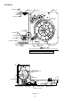
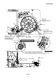
Figure 16
143
LIFT GEAR B
141
MODE BIG GEAR
133
132
104
CHANGE BOX R
147
146
128
MT IDLER GEAR F
110
Mark position
111
145
142
LIFT GEAR A
153
137
138
144
LIFT GEAR C
134
136
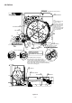
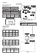
(A)
(B)
144
LIFT GEAR C
143
LIFT GEAR B
142
LIFT GEAR A
141
MODE BIG GEAR
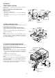
Note
(Assemble the mode big gear in this position.)
To assemble the mode
big gear, incline it,
bring it into contact with
the circumference and
put the center hole into
position since the
hatched part of the main
base is overlapped with
the circumference.
Direct the short tooth
toward the center.
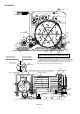
MODE BIG GEAR
LIFT GEAR A/B/C
ASSEMBLING POSITION
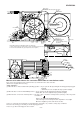
Scale: 2 magnifications
Scale: 2 magnifications
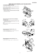
<Assembling method of lift gear>
After setting up the mode big gear in the
shown position, engage it with the STB gear A
(gear on the lower side) at the position (A),
and assemble them, turning it in the arrow direction
into the position (B). (The short tooth directs toward the
center of the mode big gear.)