
Service manual


-
PC- l600
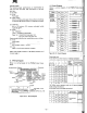
7-3. Disassembly and Assembly
This secti
on
gives step-by-step instructions for taking apart and a 55embling the PTMPG printer. It also
conta
ins the adjust
ment
methods
of
each
part
, and wiring and circuit diagrams for the circuit board on the
pr
inter.
1. DilUJembly
To take
apart
the PTMPG printer, remove the
components
from
the
frame in the
order
shown
be
low. Where neces
sa
ry,
an
explanation
is
supplied
in
the right-hand column.
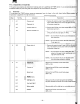
St
ep
Part
No. Component E
xp
lanation
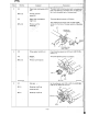
1 4·1
Z-motor unit
1 . Remove
th
e retaini
ng
ri
ng
IE tYpe) (RE1.5 ) and the
plain washer (WF2.2)
from
the Z-cam
gear
unit
w ith
4-3
Z-cam gear unit a Keystone screwdri
ve
r.
44
Z-
motor
spacer unit 2.
Remove
two
Phillips round
head
screws
(SP2
x 5) frOll
the Z-motor
unit
(4
-1).
4·2
Ejection lever shaft
unit
3.
Remove the
Z·motor
(4-1) and the Z-motor spacer
un
it
(4·4), and
then
the Z-can gear
unit
(4·3).
NO
TE
1:
Do
not
deform
the plastic part
of
the ejecti
on
lev
er
shaft
unit.
NOTE
2:
00
not
lose the washer
(W
F2.2) inside
of
th
e
Z
O(:
anl
ge
ar unit.
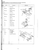
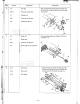
2 3-3
Platen roller unit
1.
Remove
th
e
reta
ini
ng
ring
(E
type
) (RE2)
at
the outs
id
e-
left
of
th
e frame from the platen roller unit (3·3)
wi
th
a Keys
to
ne screwdr
iv
er.
NOTE
, :
Do
not
deform the
paper
holder plates (thin
plates) of the
paper
holder
installing rest uni
ts
,
right (3-4) and left (3-5).
NOTE 2 :
Do
not
deform the pins
of
the platen roller
unit (3-3) when handling
or
storing.
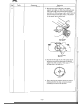
3
2·1
X-
m
otor
unit Remove the
two
P
hi
ll
ips round head screws
(SP2.3 x 3.5).
3·1
V-
m
otor
unit Remove the
two
P
hi
ll
ips round head screws
(SP2.3 x 3.
5)
.
4·7 Switch u
nit
Remove
th
e
two
Phillips round head screws
(SP2 x 3.5
).
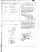
6·1
R
ubber
bush ing
6-3
Lead guide (left)
Remove the
le
ft
and right lead guides by inserting a
Keystone screwdriver between
the
frame
on
each of
th
em
64
Lead guide (right)
6·2
Wafer assembly
Remo
ve
$older with a solderi
ng
iron
or
a solder rem
ov
er.
4-6
Stopper
Remove the Phillips round head screw
(SP2 x 2.5).
-
74
-