
Service manual


Step Part
No
.
9
4:2
4-3
WF2.2
44
SP
2x
5
4-8
10
4·
1
,
Component
Ejection lever shaft
unit
Z-cam gear
unit
Pla in washers (2)
Z·motor
spacer unit
Phillips round head screw
Z-damper spring
Z-motor unit
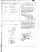
Be
PhaslI E
ne
rgizing
5V Black
Black
Yellow
Blull
Whitt
Rod
- 79 -
pc
- um
Explanation
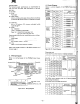
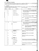
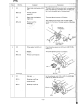
1.
Temporarily fix the Z·motor spacer unit (4·4)
onto
the frame with a
Ph
illips round head screw
(SP2 x 5).
2. Set the
eje
ction lever shaft
un
it (4-2), Z-damper
spring
(4
·
8)
, two plain washers
(WF2
.2), and Z-cam
gear
unit
(4-3), and fix them with the retaining
ring
(E
type) (RE1.5). Be careful not to deform
the
plastic part of
the
ejection lever shaft
unit
Adjust the
motor
phase and pen stroke when
setting the Z·
motor
unit (4-
11
.
RE1
.6
~
.
\WF2.2
~~.I
JJ4
.3WF2.2
~.m,.
/4"
~
.J.
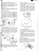
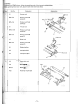
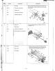
1.
Setting the Z-motor unit: remove the screw
(SP2 x
5)
which
is
tacki
ng
the Z·
motor
spacer unit
(4-4), and set the Z·
motor
unit
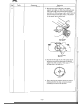
At this setting, the
cam of the Z-cam gear
un
it
(4
·3) should be
in
the
pen·up position
(E
position on page 34) and the
Z-motor should be energized
(BC
phase). The Z·
cam
gear and Z-
Iever
should be
so
engaged
that
value A
shown
in
the figure below
is
0.8
to
1.0mm. Adju$t
the
value of A by rotating the motor poniori gear
shi
le
the motor
is
being energi
z.
ed
.