
Service manual


--
PC- I600
Program
module
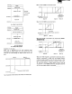
The program modules discussed here
is
the
one
that
used as
a software cartridge. The already compiled programs are
stored
in
the
module and connected with
the
computer
for
operation.
Assume now
that
there are five program modules as an
e)(ample.
PC-1600K
/
1600
G.me
Scientific
Calories Com.
"'M
IO
ftwer.
c.ICUrl11on
computing
munication
statistic
IOftw.r.
IOftwara
$Oftware
software
A
•
C D
,
Program modules
According to
the
need, the desired program module
is
connected for an immediate program execution.
®
Two program modules can
be
used at
the
same time.
When used as
the
program module,
no
user area can be
contained. But, if the module has been d
ivi
ded into a
program module and a user area using
the
INIT state-
ment, only
the
declared user area conforms
to
the
user
area of (1),
Creating
the
program module:.
After declaring
the
program area with
the
INIT
state·
ment,
the
program
is
written or loaded
to
that
area.
The
memory
protected
CE·159, CE.161,
or
CE.1600M
must
be
used
for
the
program module.
RAM
file module
With this usage,
the
completed program
or
data are saved
i
nto
the
memory module,
to
be loaded
onto
the user area
when so required.
If used as a
RAM
module,
the
module
is
not
included in
the
area.
CD
The module
that
can
be
used
the
RAM
file module
is
the
CE·161
and
CE·l600M.
® The
RAM
file module can be accessed free from
the
main unit. While it
is
removed from
the
main unit,
the
contents
are retained by
the
internal battery .
• What program
and
data are
co
ntained within
the
RAM
file module
can
be
known by means
of
the
FILES
statement
or
LFI
LES
statement.
It
is
possible
to
change
the
name
or
delete
the
program
or
data,
- 107 -
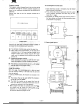
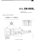
4. Consumption current
test
1. Static electricity
stor~
in human
body
must be released
before removal
of
the
board.
2. First, remove
the
lithium
battery,
and check for a short
circuit between electrodes and diodes using an ohm·
meter (R
x 1 range).
3 Connected
the
3VDC
power
supply source as shown
in
the
figure below and check
that
the
consumption power
is
less
th
an 8 microamperes.
• •
••
P.S 3V
o
a",A,
maximum
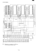
5, Parts signal layout
011 I Dip
switch
~;;;;~~
(
OSW
-S
I34lCCZZ)
CR2U2
vo
o
~
DDDDDDOO
1
01
lSSIl
r---l
{1-E:J
(V
HOISSU
III-
I )
L--.J
1~
OUODDDQO
(RC
-
SZ1007CClZ)
r~~
:
~::::~:
::::
::~~l
"
m~mmm