Important Information Setup & Connections Operation Buttons Basic Operation Useful Features & Network Function OPERATION MANUAL Maintenance & Troubleshooting MODEL LCD PROJECTOR XG-V10WU Appendix Lenses are sold separately.
Important Information Before using the LCD projector, please read this operation manual carefully. Introduction ENGLISH IMPORTANT For your assistance in reporting the loss or theft of your Color LCD Projector, please record the Serial Number located on the bottom of the projector and retain this information. Before recycling the packaging, please be sure that you have checked the contents of the carton thoroughly against the list of “Supplied Accessories” on page 13. Model No.: XG-V10WU Serial No.
Important Information IMPORTANT SAFEGUARDS Electrical energy can perform many useful functions. This product has been engineered and manufactured to ensure your personal safety. But IMPROPER USE CAN RESULT IN POTENTIAL ELECTRICAL SHOCK OR FIRE HAZARD. In order not to defeat the safeguards incorporated into this LCD Projector, observe the following basic rules for its installation, use and servicing.
Important Information IMPORTANT SAFEGUARDS "COMPLIES WITH 21 CFR SUBCHAPTER J" CAUTION LASER RADIATIONDO NOT STARE INTO BEAM WAVE LENGTH : 650nm MAX. OUTPUT : 1mW CLASS II LASER PRODUCT SHARP ELECTRONICS CORPORATION SHARP PLAZA, MAHWAH, NEW JERSEY 07430 U.S.A. ONLY TEL : 1-800-BE-SHARP REMOTE CONTROL MODEL NO. : RRMCG1564CESA DC3V (1.5VX2PCS.) MADE IN CHINA FABRIQUÉ AU CHINE AVOID EXPOSURE-LASER RADIATION IS EMITTED FROM THIS APERTURE.
Important Information IMPORTANT SAFEGUARDS Temperature Monitor Function If the projector starts to overheat due to setup problems or a dirty air filter, “TEMP.” and “ ” will flash in the lower-left corner of the picture. If the temperature continues to rise, the lamp will turn off, the TEMPERATURE WARNING indicator on the projector will flash, and after a 90-second cooling-off period the power will shut off. Refer to “Lamp/Maintenance Indicators” on page 69, for details.
Important Information Outstanding Features 1. High-end LCD Projector with Ultra High Brightness • 200 W UHP Lamps Uses two 200 W UHP lamps for excellent color uniformity and ultra high brightness. • Newly developed prism enables efficient combination of light from two lamps. A light axis separation and synthesis prism developed by Sharp enables the efficient combination of light from the two lamps.
Important Information Outstanding Features 5. Network Capability • Self-Diagnosis/Projector Status Self-diagnosis/Projector status function sends e-mail messages to a specified computer about lamp usage time and any malfunctions. • Multiple & Group Projector Control Up to 250 projectors can be controlled over a network. Projector RS-232C OUT can be used for daisy chain connection. • Simple Videowall Display Comes with software for easy videowall processing even for input from a single source. 6.
Important Information Contents Important Information Operation Buttons Setup & Connections Introduction ............................................. 1 IMPORTANT SAFEGUARDS ................... 2 Outstanding Features ............................. 5 Contents ................................................... 7 How to Access the PDF Operation Manuals ............................................... 9 Part Names............................................... 10 Supplied Accessories .........................
Using the GUI (Graphical User Interface) Menu Screen ...................... 40 Lamp/Maintenance Indicators ................ 69 Lamp Maintenance .................................. 70 40 41 43 Confirming the Lamp Usage Time ............ 70 Setting the Lamp Mode ............................. 71 Replacing the Lamp .................................. 71 46 50 Replacing the Air Filter ........................... 73 Troubleshooting ...................................... 74 For SHARP Assistance (U.S.A. only) ..
Important Information How to Access the PDF Operation Manuals PDF operation manuals in several languages are included in the CD-ROM. To utilize these manuals, you need to install Adobe Acrobat Reader on your PC (Windows or Macintosh). If you have not installed Acrobat Reader yet, you can download it from the Internet (http://www.adobe.com) or install it from the CD-ROM. To Install Acrobat Reader from the CD-ROM For Windows: 1 2 3 4 5 6 7 Insert the CD-ROM in the CD-ROM drive.
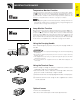
Important Information Part Names Numbers next to the part names refer to the main pages in this manual where the topic is explained.
Important Information Part Names Numbers next to the part names refer to the main pages in this manual where the topic is explained. Projector Speakers Side and Rear View Exhaust vent 3 Remote control sensor 36 LED display (ID No.
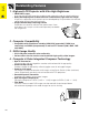
Important Information Part Names Remote Control Front View MUTE button Top View Remote control signal transmitter 31 VOLUME buttons POWER buttons 19 (ON/OFF) 31 ( / ) LENS/BLACK 29 SCREEN button 32 39 LASER POINTER/ 40 MENU button 3 Laser pointer window Rear View 37 MOUSE/ ADJUSTMENT 40 buttons (∂/ƒ/ß/©) RIGHT-CLICK/ 37 ENTER button 40 INPUT 1, 2, 3 button 31 31 INPUT 4, 5, 6 button 1.2.3 4.5.
Important Information Supplied Accessories Remote control RRMCG1564CESA Two AA size batteries RGB cable QCNW-5304CEZZ Remote mouse receiver RUNTK0673CEZZ PS/2 mouse control cable QCNW-5113CEZZ Extra air filter PFILD0110CEZZ Power cord QACCU5013CEZZ USB mouse control cable QCNW-5680CEZZ Terminal cover CCOVA1789CE01 CD-ROM UDSKA0020CEN1 LCD projector operation manual TINS-6974CEZZ LCD projector quick reference TINS-6980CEZZ Sharp Advanced Presentation Software operation manual TINS-6992CEZZ E-13
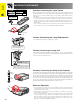
Connections Power Supply Connecting the Power Cord Setup & Connections Plug the supplied power cord into the AC socket on the side of the projector. Power cord QACCU5013CEZZ Projecting Computer Images Connecting the Projector to a Computer You can connect your projector to a computer for projection of full color computer images. Connecting to a computer using the standard 15-pin Input RGB cable QCNW-5304CEZZ 1 Connect one end of the supplied RGB cable to the INPUT 1 port on the projector.
Projecting Computer Images • This projector uses a 5 BNC computer input to prevent deterioration of image quality. • Connect the R (PR), G/G sync (Y), B (PB), HD/C sync and VD cables (sold separately) to the correct input terminals on the projector and an RGB switcher (sold separately) connected to the computer, or connect a 5 BNC cable (sold separately) directly from the input terminals on the projector to the computer.
Projecting Computer Images Connecting to a computer using the RS-232C Port When the RS-232C port on the projector is connected to a computer with an RS-232C cable (null modem, cross type, sold separately), the computer can be used to control the projector and check the status of the projector. See pages 80, 81 and 82 for details. Setup & Connections Connect an RS-232C cable (null modem, cross type, sold separately) to the serial port on the computer. RGB cable QCNW-5304CEZZ RGB cable Audio cable (3.
Watching Video Images and Laser Disc Images Connecting to a VCR, laser disc player and other audiovisual equipment using the BNC video Input 1 Connect each BNC connector of a component or video cable to the corresponding BNC INPUT 4 or 5 terminals on the projector. Setup & Connections • BNC-RCA adaptors are needed for use with RCA type cables and sources. 2 Connect the other end of the cable to the corresponding terminals on a VCR or laser disc player.
Watching DVD and Digital TV Images Connecting to a DVD player, DTV decoder and other component video equipment using the 5 BNC Input 1 Connect each BNC connector of a component cable to the corresponding BNC INPUT 2 terminals on the projector. Setup & Connections • BNC-RCA adaptors are needed for use with RCA type cables and sources. 2 Connect the other end of the cable to the corresponding terminals on a DVD player or DTV decoder.
Power ON/OFF Turning on the Main Power Setup & Connections Press the MAIN POWER switch on the side of the projector. The POWER indicator lights up red and the projector enters standby mode. • When the main power is not on, the remote control cannot be used to operate the projector. TEMP LAMP2 2 LAMP1 POWER 1 Press POWER ON. POWER buttons • The flashing green LAMP REPLACEMENT indicator shows that the lamp is warming up. Wait until the indicator stops flashing before operating the projector.
Setting Up the Screen Using the Adjustment Feet Using the Adjustment Feet Setup & Connections Rotate feet to adjust height of the projector. Up Down • The projector is adjustable up to approximately 5° from the standard position. • When the height of the projector is adjusted, the image may become distorted (keystoned), depending on the relative positions of the projector and the screen. CAUTION • Do not hold the lens when lifting or lowering the projector.
Adjusting the Projection Distance Position the projector perpendicular to the screen with all feet flat and level to achieve an optimal image. Move the projector forward or backward if the edges of the image are distorted. Setup & Connections • The projector lens should be centered in the middle of the screen. If the lens center is not perpendicular to the screen, the image will be distorted, making viewing difficult. • Position the screen so that it is not in direct sunlight or room light.
Adjusting the Projection Distance AN-LV40EZ Throw distance ratio 1.9 to 2.5:1 Diag. Screen size Width Height Projection distance (L) Maximum Minimum Setup & Connections Computer Input (5:4) Lens center to the lower edge of the screen (H) Upper Lower 600 480 360 102 4 (31.2 m) 78 9 (24.0 m) 15 0 (457.2 cm) 3 0 ( 91.4 cm) 500 400 300 85 4 (26.0 m) 65 3 (19.9 m) 12 6 (381.0 cm) 2 6 ( 76.2 cm) 400 320 240 68 3 (20.8 m) 52 2 (15.9 m) 10 0 (304.
Adjusting the Projection Distance AN-LV18MX Setup & Connections Throw distance ratio 0.9 :1 Computer Input (5:4) Diag. Screen size Width Height Lens center to the lower edge of the screen (H) Upper Lower Projection distance (L) 600 480 360 35 1 (10.7 m) 15 0 (457.2 cm) 13 6 (411.5 cm) 500 400 300 29 2 (8.9 m) 12 6 (381.0 cm) 11 3 (342.9 cm) 400 320 240 23 4 (7.1 m) 10 0 (304.8 cm) 9 0 (274.3 cm) 300 240 180 17 5 (5.3 m) 7 6 (228.
Adjusting the Projection Distance AN-LV26EZ Throw distance ratio 1.2 to 1.4 :1 Diag. Screen size Width Height Projection distance (L) Maximum Minimum Setup & Connections Computer Input (5:4) Lens center to the lower edge of the screen (H) Upper Lower 600 480 360 58 5 (17.8 m) 50 6 (15.4 m) 15 0 (457.2 cm) 0 0 (0.0 cm) 500 400 300 48 7 (14.8 m) 42 0 (12.8 m) 12 6 (381.0 cm) 0 0 (0.0 cm) 400 320 240 38 9 (11.8 m) 33 6 (10.2 m) 10 0 (304.
Adjusting the Projection Distance AN-LV36EZ Setup & Connections Throw distance ratio 1.7 to 2.7 :1 Computer Input (5:4) Diag. Screen size Width Height Projection distance (L) Maximum Minimum Lens center to the lower edge of the screen (H) Upper Lower 600 480 360 111 3 (33.9 m) 69 7 (21.2 m) 15 0 (457.2 cm) 0 0 (0.0 cm) 500 400 300 92 10 (28.3 m) 58 1 (17.7 m) 12 6 (381.0 cm) 0 0 (0.0 cm) 400 320 240 74 2 (22.6 m) 46 3 (14.1 m) 10 0 (304.
Adjusting the Projection Distance AN-LV55EZ Throw distance ratio 2.6 to 3.7 :1 Diag. Screen size Width Height Projection distance (L) Maximum Minimum Setup & Connections Computer Input (5:4) Lens center to the lower edge of the screen (H) Upper Lower 600 480 360 149 11 (45.7 m) 106 11 (32.6 m) 15 0 (457.2 cm) 0 0 (0.0 cm) 500 400 300 125 0 (38.1 m) 89 3 (27.2 m) 12 6 (381.0 cm) 0 0 (0.0 cm) 400 320 240 99 9 (30.4 m) 71 2 (21.7 m) 10 0 (304.
Adjusting the Projection Distance AN-LV80EZ Setup & Connections Throw distance ratio 3.8 to 5.3 :1 Computer Input (5:4) Diag. Screen size Width Height Projection distance (L) Maximum Minimum Lens center to the lower edge of the screen (H) Upper Lower 600 480 360 215 7 (65.7 m) 153 10 (46.9 m) 15 0 (457.2 cm) 0 0 (0.0 cm) 500 400 300 179 6 (54.7 m) 127 11 (39.0 m) 12 6 (381.0 cm) 0 0 (0.0 cm) 400 320 240 143 4 (43.7 m) 102 4 (31.2 m) 10 0 (304.
Adjusting the Projection Distance Upper and Lower Lens Shift Position • This projector is equipped with a lens shift function that lets you adjust the projection height. • Adjust to match the setup configuration. Setup & Connections Screen size: 100 inches (254 cm) Computer Input: 5:4 AN-LV40EZ as an example Screen Lens center Upper lens shift position H: 2 6 (76.
LENS Button Projector Remote Control This function can be used to adjust the focus, zoom, lens shift, keystone and digital shift settings. 1, 4a 3 4b Setup & Connections 2 4b On-screen Display (Example: 5:4 NORMAL image) Digital Image Adjustments 1.2.3 (Slide the MOUSE/ADJUSTMENT switch on the remote control to the ADJ. position.) ADJ. 1 Press LENS to select mode. Each time LENS is pressed, the screen changes as shown on the left. 2 Press ENTER to display test pattern.
Image Projection Rear Projection Setup & Connections • Place a translucent screen between the projector and the audience. • Use the projector’s menu system to reverse the projected image. (See page 56 for use of this function.) • Optimal image quality can be achieved when the projector is positioned perpendicular to the screen with all feet flat and level.
Using the Operation Buttons Selecting the Input Signal Source Projector Remote Control Press INPUT 1.2.3 or INPUT 4.5.6 again to change the mode. • When no signal is received, “NO SIGNAL” will be displayed. When a signal that the projector is not preset to receive is received, “NOT REG.” will be displayed. INPUT buttons On-screen Display Operation Buttons 1.2.3 INPUT 1 Mode INPUT 2 Mode INPUT 3 Mode INPUT 4 Mode INPUT 5 Mode INPUT 6 Mode 4.5.
Superimposing a Black Screen Projector Remote Control This function can be used to superimpose a black screen over the projected image. Blacking out the Projected Image Press BLACK SCREEN. The screen turns black and “BLACK SCREEN” is displayed on the screen. To return to the original projected image, press BLACK SCREEN again. BLACK SCREEN button 1.2.3 4.5.6 • To use the remote control to operate this function, slide the MOUSE/ADJUSTMENT switch to the MOUSE position before pressing BLACK SCREEN.
Magnifying a Specific Portion of an Image Projector Remote Control 2 3 1.2.3 4.5.6 1 3 Operation Buttons On-screen Display This function allows you to magnify a specific portion of an image. This is useful when you want to display a detailed portion of the image. (Slide the MOUSE/ADJUSTMENT switch on the remote control to the ADJ. position) MOUSE ADJ. 1 Press ENLARGE. Each time ENLARGE is pressed, the image will be magnified.
Adjusting the Picture Aspect Ratio Projector Remote Control This function allows you to modify or customize the picture display mode to enhance the input image. Depending on the input signal, you can choose NORMAL, FULL, DOT BY DOT, BORDER, STRETCH or SMART STRETCH image. 2 1.2.3 1 Press RESIZE. Each time RESIZE is pressed, the picture mode changes as shown below. 4.5.6 1 2 To return to the standard image, press UNDO while “RESIZE” is displayed on the screen.
Gamma Correction Function Projector Remote Control 2 1.2.3 4.5.6 1 Operation Buttons 2 On-screen Display s STANDARD GAMMA 1 • Gamma is an image quality enhancement function that offers a richer image by brightening the darker portions of the image without altering the brightness of the brighter portions. • Four gamma settings are available to allow for differences in the images displayed and in the brightness of the room.
Selecting the Remote Control Mode Operation Buttons Using the Remote Control as a Wireless Mouse The remote control has the following three functions: • Projector control • Wireless mouse • Laser pointer MOUSE/ADJUSTMENT switch (Remote control) MOUSE ADJ. Wireless mouse/ Laser pointer MOUSE ADJ. Projector control Operating the Remote Control Remote Control/Mouse Receiver Positioning • The remote control can be used to control the projector within the ranges shown below.
Operating the Remote Control Use as a Wireless Mouse Be sure the supplied remote mouse receiver is connected to your computer. Slide the MOUSE/ADJUSTMENT switch to MOUSE. MOUSE mode buttons LASER POINTER BLACK SCREEN LEFT-CLICK Operation Buttons MOUSE RIGHT-CLICK 1.2.3 MOUSE/ ADJUSTMENT switch MOUSE 4.5.6 ADJ. BACKLIGHT Conference Series • For one-button mouse systems, use either the LEFT-CLICK or RIGHT-CLICK button. • Press BACKLIGHT, and the buttons will light up.
Connecting the Mouse Receiver Connecting the Remote Mouse Receiver You can use the remote control as a remote mouse to operate computers compatible with PS/2 or USB type mouse systems. 1.2.3 4.5.6 Conference Series Connecting to the USB port on a PC or Macintosh 1 Connect one end of the supplied USB mouse control cable to the corresponding terminal on the computer. 2 Connect the other end to the USB port on the remote mouse receiver.
Using as a Laser Pointer Use as a Laser Pointer Slide the MOUSE/ADJUSTMENT switch to MOUSE, and press LASER POINTER ( the laser pointer. ) to activate LASER POINTER 4.5.6 Operation Buttons 1.2.3 MOUSE ADJ. MOUSE/ADJUSTMENT switch Conference Series • When the button is released, the light automatically goes off. • For safety reasons, the laser pointer automatically goes off after 1 minute of continuous use. To turn it on, release LASER POINTER ( ) and press again.
Using the GUI (Graphical User Interface) Menu Screen Basic Operations Projector Remote Control 1, 7 2, 3, 5 6 4 6 1.2.3 4.5.6 This projector has two sets of menu screens that allow you to adjust the image and various projector settings. These menu screens can be operated from the projector or the remote control with the following procedure.
Menu Bars Items on the INPUT 1, 2 or 3 Mode Menu Bar Main menu Picture Main menu Sub menu ⳮ30 Ⳮ30 Bright ⳮ30 Ⳮ30 Color ⳮ30 Ⳮ30 Tint ⳮ30 Ⳮ30 Lamp 1 Only Sharp ⳮ30 Ⳮ30 Lamp 2 Only Red ⳮ30 Ⳮ30 Blue ⳮ30 Ⳮ30 ⳮ3 CLR Temp Ⳮ3 Options Lamp Mode Both Lamps Lamp 2 Equal Use RGB PRJ Mode CeilingⳭFront Component Rear 3D Progressive CeilingⳭRear Clock Film Mode ⳮ150 Ⳮ150 ⳮ60 Ⳮ60 ⳮ150 Ⳮ150 V-Pos ⳮ60 Ⳮ60 1 2 Stack Setting Vert Freq 75 Hz 72 Hz Slave Keylock Level • Vert Fre
Menu Bars Items on the INPUT 4 or 5 Mode Menu Bar Main menu Picture Main menu Sub menu Sub menu Contrast ⳮ30 Ⳮ30 Bright ⳮ30 Ⳮ30 Color ⳮ30 Ⳮ30 Tint ⳮ30 Ⳮ30 Lamp 1 Only Sharp ⳮ30 Ⳮ30 Lamp 2 Only Red ⳮ30 Ⳮ30 Blue ⳮ30 Ⳮ30 ⳮ3 CLR Temp Options Lamp Timer Lamp 1 Lamp Mode Both Lamps Lamp 2 Equal Use PRJ Mode Ⳮ3 CeilingⳭFront Reset Rear Signal Type CeilingⳭRear Video Component Progressive Mode Stack Setting 2D Progressive Slave Film Mode Balance ⳮ30 Ⳮ30 Treble ⳮ30
Adjusting the Picture Projector Remote Control You can adjust the projector’s picture to your preferences with the following picture settings. Description of Adjustment Items 1, 4 2, 3 1.2.3 4.5.6 (GUI) On-screen Display e. g.
Adjusting the Picture Projector Remote Control Adjusting the Color Temperature This function can be used to adjust the color temperature to suit the type of image input to the projector (video, computer image, TV broadcast, etc.). Decrease the color temperature to create warmer, reddish images for natural flesh tones. Increase the color temperature to create cooler, bluish images for a brighter picture. 1, 4 2, 3 Description of Color Temperature ⳮ3 1.2.3 (GUI) On-screen Display 4.5.
Adjusting the Picture Projector Remote Control Selecting the Signal Type This function allows you to select the input signal type RGB (VIDEO) or COMPONENT for INPUT 1, 2, 4 or 5 port. 1, 5 (Slide the MOUSE/ADJUSTMENT switch on the remote control to the ADJ. position.) 2, 3 4 MOUSE ADJ. 1 Press MENU. Menu bar and “Picture” menu screen appear. GUI operation guide is also displayed. 1.2.3 4.5.6 2 Press ∂/ƒ to select “Signal Type”, and then press ©.
Adjusting the Computer Images (RGB menu only) Projector Remote Control 1, 5 2, 3, 4 Description of Adjustment Items 1.2.3 (GUI) On-screen Display 2 When displaying computer patterns which are very detailed (tiling, vertical stripes, etc.), interference may occur between the LCD pixels, causing flickering, vertical stripes, or contrast irregularities in portions of the screen. Should this occur, adjust “Clock”, “Phase”, “H-Pos” and “V-Pos” for the optimum computer image. 4.5.
Adjusting the Computer Images (RGB menu only) Projector Remote Control Saving and Selecting Adjustment Settings This projector allows you to store up to seven adjustment settings for use with various computers. Once these settings are stored, they can be easily selected each time you connect a computer to the projector. 1, 6 2, 3, 4 Saving the adjustment setting 5 (Slide the MOUSE/ADJUSTMENT switch on the remote control to the ADJ. position.) 1.2.3 4.5.6 MOUSE ADJ. 1 Press MENU.
Adjusting the Computer Images (RGB menu only) Projector Remote Control Special Mode Adjustment Ordinarily, the type of input signal is detected and the correct resolution mode is automatically selected. However, for some signals, the optimal resolution mode in “Special Modes” on the “Fine Sync” menu screen may need to be selected to match the computer display mode. 1, 6 2, 3, 4 5 (Slide the MOUSE/ADJUSTMENT switch on the remote control to the ADJ. position.) 1.2.3 4.5.6 MOUSE ADJ. 1 Press MENU.
Adjusting the Computer Images (RGB menu only) Projector Remote Control • Used to automatically adjust a computer image. • Auto Sync adjustment can be made manually by pressing AUTO SYNC, or automatically by setting “Auto Sync” to “ON” in the projector’s GUI menu. 1, 5 2, 3, 4 AUTO SYNC button Auto Sync Adjustment 1.2.3 4.5.
Adjusting the Sound Projector Remote Control This projector’s audio is factory preset to standard settings. However, you can adjust it to suit your own preferences by adjusting the following audio settings. Description of Adjustment Items 1, 5 2, 3, 4 Selected item ß button Balance Increased audio from the left Increased audio from the right speaker speaker For weaker treble For stronger treble For weaker bass For stronger bass All audio adjustment items are returned to the factory preset settings.
Displaying Dual Pictures (RGB menu only) Projector Remote Control 1, 6 Picture in Picture function allows you to display two pictures on the same screen. You can display the image input from INPUT 4 or 5 as an inset picture overlapping the main picture input from INPUT 1, 2 or 3. (Slide the MOUSE/ADJUSTMENT switch on the remote control to the ADJ. position.) 2, 3 4, 5 MOUSE ADJ. 1 Press MENU. 2 Press ß/© to select “Options (1)”. 1.2.3 (GUI) On-screen Display 4.5.
Reducing Image Noise (VIDEO menu only) Projector Remote Control 3D Digital Noise Reduction (3D DNR) provides high quality images with minimal dot crawl and cross color noise. (Slide the MOUSE/ADJUSTMENT switch on the remote control to the ADJ. position.) 1, 4 2, 3 MOUSE ADJ. 1 Press MENU. 2 Press ß/© to select “Options (1)”. 1.2.3 4.5.6 3 Press ∂/ƒ to select “3D DNR”, and then select “ ”. 4 To exit from the GUI, press MENU.
Turning On/Off the On-screen Display Projector Remote Control This function allows you to turn on or off the on-screen messages that appear during input select. Description of OSD Display 1, 6 2, 3, 4 5 Selected item Description Normal Level A All On-screen Display are displayed. INPUT, CUSTOM, FREEZE, ENLARGE, AUTO SYNC, VOLUME, MUTE, BLACK SCREEN are not displayed. All On-screen Display are not displayed (except warning display (MENU, TOOLS, LENS, Power off, Temp., Lamp etc.)). Level B 1.2.3 4.5.
Selecting a Background Image Projector Remote Control This function allows you to select the image displayed when no signal is being sent to the projector. Description of Background Images 1, 6 2, 3, 4 5 1.2.3 4.5.6 Selected item Description Sharp SHARP default image Custom User customized image (i.e. company logo) Blue Blue screen None Black screen (Slide the MOUSE/ADJUSTMENT switch on the remote control to the ADJ. position.) MOUSE ADJ. 1 Press MENU. 2 Press ß/© to select “Options (1)”.
Selecting the Economy Mode Projector Remote Control These functions allow you to reduce the power consumption when the projector is in standby mode. Monitor Out/RS-232C Off Function This projector consumes power when using a monitor connected to the OUTPUT port for INPUT 1, 2 and a computer connected to the RS-232C port. When not using these ports, “MNTR Out/RS232C” can be set to “ ” to reduce standby power consumption. 1, 5 2, 3, 4 Description of Monitor Out/RS-232C Off 1.2.3 4.5.
Selecting the Economy Mode Projector Remote Control ID No. Display Off Function The LED ID number display on the rear of the projector, used when controlling multiple projectors, can be turned on or off. 1, 6 Description of ID No. Display 2, 3, 4 Selected item Display Off 5 Standby Off Display On 1.2.3 Description Not displayed Displayed except when the projector is in standby mode. Always displayed 4.5.6 (Slide the MOUSE/ADJUSTMENT switch on the remote control to the ADJ. position.
Selecting the On-screen Display Language Projector Remote Control 1, 5 English is the preset language for the On-screen Display; however, this can be changed to German, Spanish, Dutch, French, Italian, Swedish, Portuguese, Chinese, Korean or Japanese. (Slide the MOUSE/ADJUSTMENT switch on the remote control to the ADJ. position.) 2, 3 4 MOUSE ADJ. 1 Press MENU. 2 Press ß/© to select “Language”. 1.2.3 4.5.6 3 Press ∂/ƒ to select the desired language.
Displaying the Adjustment Settings Projector Remote Control This function can be used to display all the adjusted settings on the screen simultaneously. (Slide the MOUSE/ADJUSTMENT switch on the remote control to the ADJ. position.) 1, 4 2 1 Press MENU. 3 2 Press ß/© to select “Status”. MOUSE ADJ. 3 Press ENTER to display all the adjustment settings. 1.2.3 4.5.6 4 To exit from the GUI, press MENU.
Useful Features Locking the Operation Buttons on the Projector Projector Remote Control This function can be used to lock the use of certain operation buttons on the projector. The user can still operate the projector fully with the remote control. Description of Keylock Levels 1, 6 Selected item Normal Level A 2, 3, 4 5 Level B 1.2.3 4.5.6 Description All operation buttons are functional. Only INPUT, VOLUME, MUTE, BLACK SCREEN on the projector are available.
Selecting the Transmission Speed (RS-232C) Projector Remote Control This menu allows you to adjust the transmission speed of the RS-232C connection by selecting the baud rate. (Slide the MOUSE/ADJUSTMENT switch on the remote control to the ADJ. position.) 1, 6 2, 3, 4 MOUSE ADJ. 1 Press MENU. 5 2 Press ß/© to select “Options (2)”. 1.2.3 4.5.6 3 Press ∂/ƒ to select “RS-232C”, and then press ©. 4 Press ∂/ƒ to select the desired baud rate. (GUI) On-screen Display 5 Press ENTER to save the setting.
Protecting Important Settings with a Password Projector Remote Control A password can be set by the user and used with the keylock level to prevent adjustments to certain settings on the GUI. 1, 6 • When password is set, you need to enter the password to use “Lamp Mode”, “PRJ Mode”, “Stack Setting”, “Keylock Level”, “Set Inputs”, “RS-232C” and “Set ID No.” menus. 2, 3 4, 5 Setting the Password 1.2.3 (GUI) On-screen Display Setting the Password 4.5.
Network Function Setting Up the Optional Boards Three optional Expansion Boards from Sharp are also available for specialized application. Please see your local Sharp Industrial LCD Products Dealer for details on these boards. Be sure to have service personnel install optional boards.
Controling Multiple Projectors with ID Numbers Projector Remote Control This projector can form a network of up to 250 projectors. To identify separately and control specified projector, you need to set ID No.. The ID No. you set is displayed on the LED. 1, 6 (Slide the MOUSE/ADJUSTMENT switch on the remote control to the ADJ. position.) 2, 3, 4 5 MOUSE ADJ. Setting the ID No. 1 Press MENU. 1.2.3 4.5.6 2 Press ß/© to select “Options (2)”. 3 Press ∂/ƒ to select “Set ID No.”. (The ID No.
Using the Presentation Tools Projector This projector is equipped with presentation tools that can be used to emphasize keypoints within your presentation. Remote Control 2, 4 3, 5 (Slide the MOUSE/ADJUSTMENT switch on the remote control to the ADJ. position.) 6 1.2.3 MOUSE ADJ. 4.5.6 1 Press TOOLS to display the presentation tools menu window on the screen. 1 6 2 Press ∂/ƒ/ß/© to select the desired tool and color. On-screen Display 3 Press ENTER to select it.
Operating the Network Function This projector has outstanding network capability. • Internet access for self-diagnosis • Multiple and group projector control • Simultaneous multiple projector control 1.
Operating the Network Function 2. Multiple and group projector control via computer Building A RS-232C 3rd Floor RS-232C Control PC Sharp Advanced Presentation Software “Professional Edition” 2nd Floor RS-232C 1st Floor Optional RS-422 board RS-422 Video Source 1 Video Source 2 To Building B RS-422 Useful Features & Network Function This projector can be used in a network of projectors managed from a single PC with the accompanied Sharp Advanced Presentation Software—Professional Edition.
Operating the Network Function 3.
Operating the Network Function Videowall RGB SOURCE1 001 RGB SOURCE2 VIDEO SOURCE2 Master 003 Slave OUTPUT INPUT1 OUTPUT INPUT2 DVD INPUT2 INPUT4 INPUT5 OUTPUT RS-232C IN RS-232C OUT INPUT4 INPUT5 OUTPUT RS-232C IN RS-232C OUT Useful Features & Network Function VIDEO SOURCE1 INPUT1 Master Set Inputs INPUT1 Yes INPUT2 Yes INPUT3 No INPUT4 Yes INPUT5 Yes INPUT6 No DVD 002 INPUT1 Control PC Sharp Advanced Presentation Software “Professional Edition” Slave 004 Slave OUTPUT INPUT1
Lamp/Maintenance Indicators Maintenance Indicators TEMP LAMP2 2 TEMPERATURE WARNING indicator LAMP1 POWER 1 LAMP 2 LAMP 1 POWER REPLACEMENT REPLACEMENT indicator indicator indicator Maintenance Indicator TEMPERATURE WARNING indicator LAMP REPLACEMENT indicator POWER indicator Condition • The warning lights on the projector indicate problems inside the projector.
Lamp Maintenance Confirming the Lamp Usage Time Lamp The lamp in this projector operates for approximately 1,000 cumulative hours, depending on the usage environment. (As the usage environment can vary significantly, the projector lamp may not operate for 1,000 hours.) It is recommended that the lamp be replaced after approximately 900 cumulative hours of use or when you notice a significant deterioration of the picture and color quality. The lamp usage time can be checked with the On-screen Display.
Setting the Lamp Mode Projector Remote Control 1, 6 This function can be used to set the lamp mode. The mode can be set to double the effective lamp usage time. Description of Lamp Mode 2, 3, 4 5 1.2.3 Selected item Description Both Lamps Both lamps are used for greater brightness. Lamp 1 Only Lamp 1 is used. When lamp 1 burns out, automatically switches to lamp 2. Lamp 2 Only Lamp 2 is used. When lamp 2 burns out, automatically switches to lamp 1.
Replacing the Lamp Removing and installing the lamp unit CAUTION • Be sure to remove the lamp cage by the handle. Be sure not to touch the glass surface of the lamp cage or the inside of the projector. • To avoid injury to yourself and damage to the lamp, be sure to carefully follow the steps below. • Replace the lamp more safely by unplugging the power cord after turning off the main power. Lamp 1 Lamp 2 High angle view 1 Turn off the power. Press POWER OFF. Wait until the cooling fan stops.
Replacing the Air Filter • This projector is equipped with one air filter to ensure the optimal operating condition of the projector. • The air filter should be exchanged after every 2,000 hours of use. • Have your nearest Authorized Sharp Industrial LCD Products Dealer or Service Center exchange the filter (PFILD0110CEZZ). Front View Air filter Replacing the front air filter 1 Turn off the power. 2 Turn off the main power and unplug the power cord. 3 Remove the front filter cover.
Troubleshooting Problem Power cannot be turned on or off using the POWER buttons (ON/OFF) on the projector. Check • Keylock level is set to “Level A” or “Level B”, preventing operation of some or all buttons. (See page 59.) Cannot be operated by remote control. • When the projector is set to slave, use the buttons on the master projector or change the setting by RS-232C commands from the computer. (See page 63.) Cannot be operated by all buttons of the projector and remote control.
Guide to Effective Presentations Electronic presentations are one of the most effective tools presenters can use to persuade an audience. There are several ways to enhance your presentation and maximize your effectiveness. The following are guidelines to help you create and deliver a dynamic presentation. a. Types of Presentations Computer Presentations • To present basic information such as graphs, spreadsheets, documents and images, use word processing and spreadsheet applications.
Guide to Effective Presentations • Background colors can subconsciously affect the audience: Red Blue Red—increases viewers’ pulse and breathing and encourages risk taking but can also be associated with financial loss. Blue—has a calming and conservative affect on the audience but can also create boredom among corporate audiences that are often inundated with this background color. Green—stimulates interaction. Green Black Black—conveys finality and certainty.
Guide to Effective Presentations Good Bad Good c. Set-Up When giving a presentation, you need to set the stage both figuratively and literally for success. The way you set up a presentation room will have a great impact on the audience’s perception of you and your message. By manipulating the placement and use of the following tools, you will improve the impact of your presentation.
Guide to Effective Presentations d. Rehearsing & Delivery • The best time to rehearse is the day or evening before, not a couple of hours before, and the best place to rehearse is in the actual room. Rehearsing a speech in a small office is not the same as standing up in front of 100 people in a hotel ballroom or classroom. • Due to varying processor speeds of computers, practice your slide transitions for proper timing.
Connecting Pin Assignments INPUT 1 RGB and OUTPUT (INPUT 1, 2) Signal Input Ports: 15-pin Mini D-sub female connector 5 10 15 1 6 11 RGB Input Analog 1. Video input (red) 2. Video input (green/sync on green) 3. Video input (blue) 4. Reserve input 1 5. Composite sync 6. Earth (red) 7. Earth (green/sync on green) Component Input Analog 1. PR (CR) 2. Y 3. PB (CB) 4. Not connected 5. Not connected 6. Earth (PR) 7. Earth (Y) 8. Earth (PB) 8. 9. 10. 11. 12. 13. 14. 15.
(RS-232C) Specifications and Command Settings PC control A computer can be used to control the projector by connecting an RS-232C cable (null modem, cross type, sold separately) to the projector. (See page 16 for connection.) Communication conditions Set the serial port settings of the computer to match that of the table. Signal format: Conforms to RS-232C standard.
(RS-232C) Specifications and Command Settings E-81 COMMAND PARAMETER CONTROL CONTENTS RETURN COMMAND PARAMETER RETURN INPUT 2 (RGB 2) SIGNAL TYPE : RGB INPUT 1 (RGB 1) RESIZE : FULL R A S R _ _ _ 5 OK OR ERR INPUT 2 (RGB 2) SIGNAL TYPE : COMPONENT I B S I _ _ _ 1 OK OR ERR INPUT 1 (RGB 1) RESIZE : DOT BY DOT R A S R _ _ _ 3 OK OR ERR INPUT 1 (RGB 1) 2D PROGRESSIVE R A I P _ _ _ 0 OK OR ERR INPUT 2 (RGB 2) RESIZE : NORMAL R B S R _ _ _ 1 OK OR ERR INPUT 1 (RGB 1) 3D PROGRESSIVE R A I P _ _
(RS-232C) Specifications and Command Settings COMMAND PARAMETER CONTROL CONTENTS RETURN COMMAND PARAMETER RETURN LAMP 1 USAGE TIME T L T T _ _ _ 1 0–9999 (INTEGER) RGB HORIZONTAL FREQUENCY CHECK T F R Q _ _ _ 1 kHz (***. *OR_) LAMP 2 USAGE TIME T L T T _ _ _ 2 0–9999 (INTEGER) RGB VERTICAL FREQUENCY CHECK T F R Q _ _ _ 2 Hz (***.
Wired Remote Control Terminal Specifications Specifications of wired remote control input • ø3.
Computer Compatibility Chart Horizontal Frequency: 15–126 kHz Vertical Frequency: 43–200 Hz Pixel Clock: 12–230 MHz Compatible with sync on green and composite sync signals UXGA (1,600 1,200) compatible in advanced intelligent compression AICS (Advanced Intelligent Compression and Expansion System) resizing technology PC/ MAC/ WS Resolution 640 350 720 350 640 400 720 400 VGA 640 480 PC SVGA XGA 800 600 1,024 768 PC/ MAC/ WS Horizontal Frequency (kHz) Vertical Frequency (Hz)
Dimensions Rear View Side View Top View 5 32 / (3.9) 16 5/16 (414.5) 24 29/64 (621.3) 2 15/16 (74.5) Side View 17 31/64 (444.2) 14 51/64 (376) 1 1/64 (25.65) 3 7/32 (81.85) Front View 8 47/64 (221.
Specifications Product type LCD Projector Model XG-V10WU Video system PAL/PAL 60/PAL-M/PAL-N/SECAM/NTSC 3.58/NTSC 4.43 DTV 480i/480P/720P/1080i Display method LCD panel 3, RGB optical shutter method LCD panel Panel size: 1.8 (28.7 [H] 35.8 [W] mm) Display method: Translucent TN liquid crystal panel Drive method: TFT (Thin Film Transistor) Active Matrix panel No.
Glossary Anti-aliasing digital keystone correction Function to digitally correct a distorted image when the projector is set up at an angle. Aspect ratio Width and height ratio of an image. The normal aspect ratio of a computer and video image is 4 : 3. There are also wide images with an aspect ratio of 16 : 9 and 21 : 9. Auto sync Optimizes projected computer images by automatically adjusting certain characteristics. Background Initial setting image projected when no signal is being input.
Index A AC socket ......................................................................... Adjusting the Picture ........................................................ Adjustment Feet ............................................................... ADJUSTMENT switch ....................................................... Air filter ............................................................................. Anti-aliasing digital keystone correction .......................... Aspect ratio ................
Appendix SHARP CORPORATION E-89