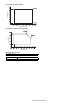
2. Production number identification 3. Environment conditions
A. Ambient conditions for transporting Serial number (0001-9999) The end digit of production year ~ Destination ~ Unit version Production month 1 January September October November December 9 0 X Y Humidity (%) The label on the TD cartridge shows the date of production. Temperature (˚C) Humidity (%) B. [5] UNPACKING AND INSTALLATION 1. Removal of protective material and fixing screw 1) Remove all tapes, then open the document cover and remove the protective material of sheet shape. 2) Remove the fixing screw using a coin. The fixing screw is required when transporting the machine. Keep it in the tray. (Refer to the later description.) Fixing screw ∗ If power is turned don without removing the fixing pin, it will be diffi- cult to pull out the tray. 3. 4. Toner cartridge installation • Screen display 1) Shake the toner cartridge several times horizontally, and remove the tape. 4 or 5 times 3) On the screen, all trays are indicated and the previously selected tray is highlighted. Use the Up/Down key to select the tray desired. Shutter • Screen display Tape Knob ∗ Do not hold the shutter lever when shaking. 2) Press the lock release lever, and insert the unit completely into the copier along the guide groove. [6] EXTERNAL VIEW AND INTERNAL STRUCTURE 1. External view 1 9 8 2 3 7 10 6 11 12 13 5 14 4 No. 1 2 3 4 5 6 7 8 9 10 11 12 13 14 Name Platen cover Paper output tray Front cover Paper trays Power switch Handles Operation panel Original table Upper exit area cover Side cover Side cover handle Bypass tray guides Bypass tray Bypass tray extension Function/Operation Place the original on the original table and close the platen cover before copying starts. 3. Operation panel A. Key position 1 2 12 13 14 3 15 16 17 4 18 5 6 7 19 20 21 8 9 22 10 11 23 These keys and indicators are not used for the copier features No. 1 Name COPY key and indicator Function/Operation Press to select the COPY mode. Press and hold during standby to display the total output count. Quantity of toner remaining is also displayed. Displays information to assist the operator. Press to return the display to the previous screen. 4. Motor, Solenoid, Clutch 5. Sensor 2 3 1 1 4 17 2 5 16 6 3 7 4 8 5 9 6 26 10 11 12 13 14 7 8 25 9 13 12 11 17 24 15 10 27 23 18 22 21 14 No. No. [7] ADJUSTMENTS, SETTING 1. (5) Grid bias voltage adjustment (Low mode) (SIM 8-3) 1) Execute SIM 8-3. Sim8-3 MHV(L) COPY 1:AE 3 2:TEXT 5 3:TEXT/PHOTO 5 1/2 2) After selecting the mode, enter the adjustment value and press the [OK] key. 3) Output will be made for 30 sec. Setup of various copy conditions: Similar to the normal copy mode. 2) Measure the distance H between the paper lead edge and the image print start position. Set the image print start position set value again. • 1 step of the set value corresponds to about 0.127mm shift. • Calculate the set value from the formula below. 99 – H/0.127 (mm) = Image print start position set value 0mm 0mm 5 3) Check the copy output. (Initial screen) (Input screen) (6) Left edge void area adjustment (Executing screen) Note: Before performing this adjustment, be sure to check that the paper off center adjustment (SIM 50-10) is completed. Sim50-10 PRT.CENTER 1:BYPASS 50 2:TRAY1 50 3:TRAY2 50 1/2 50 1) Set a test chart (UKOG-0089CSZZ) on the document table. 2) Select a paper feed port and make two copies. 3) Manually turn the mirror base drive pulley and bring No. 2/3 mirror base unit into contact with the positioning plate. At that time, if the front frame side and the rear frame side of No. 2/ 3 mirror base unit are brought into contact with the positioning plate at the same time, the mirror base unit parallelism is proper. 6) Put No. 2) Open the original cover and make a normal (100%) copy. • When a following copy is made. 3) Measure the width of the black background at the lead edge and at the rear edge. Original Copy A Copy B 1) Make an original for the adjustment. Make test sheet by drawing parallel lines at 10mm from the both ends of A3 (11" x 17") white paper as shown below. (These lines must be correctly parallel to each other. • When La > Lb Shift the mirror base B rail upward by the half of the difference of La–Lb. • When La < Lb Shift the mirror base B rail downward by the half of the difference of Lb–La. Example: When La = 12mm and Lb = 9mm, shift the mirror base B rail upward by 1.5mm. • When Lc >Ld Shift the mirror base B rail downward by the half of the difference of Lc–Ld. • When Lc < Ld When Lc < Ld, move the mirror base B on the paper feed side upward. 6) Enter the set value and press the start key. The set value is stored and a copy is made. 7) Execute SIM 48-1-5. The current back surface sub scanning direction magnification ratio is displayed in two digits on the display section. 3) If the distance is outside the specified range, adjust the open/close sensor attachment plate position as shown below. OC (SPF) open/close position A: 125 – 225mm 8) Enter the set value and press the start key. ∗ When the lens unit is moved, execute the OC main scanning magni- fication ratio auto adjustment, SIM 48-1-1, SIM48-3 and the SPF original off-center adjustment. C. Image density (exposure) adjustment (1) Copy mode (SIM46-2) 1) Set a test chart (UKOG-0162FCZZ) on the OC table as shown below. ∗ This adjustment is basically O.K. with SIM 63-7. (16) SPF scan position auto adjustment Rear [Function] Used to adjust the SPF scan position automatically. [8] SIMULATION 1. Operating procedures and operations Screen Maginification ratio selection A. Basic operation Procedure Key operation Execution 1 Simulation mode selection # → INTERRUPT → C → INTERRUPT 2 Main code selection 10-key (Input main code) → START 3 Sub code selection 10-key (Input sub code) → START 4 Selection of the mode and item 5 Start simulation operation Returns to the sub code 6 selection. 2. Simulation code list For sub codes marked with "*", only display is provided. (Cannot be executed.) Code Main Sub 1 1 2 2 1 2 3 3 2 3 4 6 7 11 2 3 5 1 2 3 6 1 2 7 8 1 6 8 1 2 3 10 11 12 13 14 15 Code Main Sub 9 1 Function Used to check the operation of the scanner unit and its control circuit. Used to check the operation of sensor and detector in the scanning (read) section and the related circuit. Used to check the operation of the SPF unit and the related circuit. Code Main Sub 25 2 26 1 2 3 5 6 *10 *12 *14 *18 20 22 30 35 36 37 38 41 46 50 54 57 60 27 1 30 5 1 2 40 1 2 3 Function Used to make the initial setting of toner concentration when replacing developer. Used to set options. (This simulation is used to make option setting when an option is installed.) Used to detect the paper size. Used to set the specifications of the auditor. Setting must be made depending on the use condition of the auditor. Code Main Sub 51 8 9 53 61 63 8 1 1 7 64 65 66 67 1 5 1 2 3 4 6 7 8 10 11 13 17 21 *22 30 32 34 37 38 41 50 51 52 53 *11 *14 *17 *18 *20 3. Details Function Used to set to disable the operation of the separation pawl of the photoconductor drum. Used to adjust ON/OFF timing of the separation voltage. Used to adjust the mirror unit SPF scan position automatically. (Initial screen) (Input/Selection screen) (Executing screen) Sim2-1 SPF AGING 115% A3 1SIDE 100% 2SIDE 86% ZOOM <100%> 0 Sim2-1 SPF AGING 115% A3 1SIDE 100% 2SIDE 86% ZOOM <100%> EXEC Sim2-1 SPF AGING 115% A3 1SIDE 100% 2SIDE 86% ZOOM <100%> EXEC The magnification ratio can be selected in the range of 50% – 200% in 9 steps with ↑ ↓ keys. 8:OGSLR Transport selection gate solenoid (R) 9:OGSLL Transport selection gate solenoid (L) 10:JGSL1 Rear edge plate drive solenoid 11:JGSL2 Upper alignment plate drive solenoid 12:SHTSL Shutter drive solenoid 13:T2SCL Paper exit roller clutch 14:STGSL Paper holding solenoid The finisher main motor operates for 10sec, the staple motor 5 times, the tray lift-up motor one reciprocating operation, other motors max. 4-3 3-11 Purpose Operation test/check Function Used to check the operation of the shifter. (Purpose) Item Operation Operation/procedure Purpose Operation test/check Function Used to check the operation of the load in the option (Purpose) tray and the control circuit. Section Paper feed Item Operation Operation/procedure [Selection 1] Select the load to check with the 10-key. During execution of load operation, [EXEC] is highlighted. Pressing the [BACK] key under this state interrupts the operation. 5-2 Purpose Operation test/check Function Used to check the operation of the heater lamp and the (Purpose) control circuit. Section Fixing (Fusing) Item Operation Operation/procedure Press the [OK] key. ON/OFF operation of the heater lamp is repeated 5 times in an interval of 500ms. When selected without setup, the selected value is registered and highlighted. When selected with previous setup, the previous setup is canceled and it is displayed normally. This setting is canceled by power OFF. Note: In SIM 7-1, pressing [CA] key terminates the simulation and the machine enters the aging mode without resetting. Therefore, to perform "4. Intermittent setup," the intermittent cycle must be set with SIM 7-6 in advance. Reset is not performed when the machine enters the aging mode. NO. 1 2 3 4 5 6 7 8 Set value 480 505 530 555 580 605 630 655 Grid High –480V –505V –530V –555V –580V –605V –630V –655V Grid Low –350V –375V –400V –425V –450V –475V –500V –525V 8-10 Purpose Function (Purpose) Adjustment/Operation test/check Used to check and adjust the operation of the developing bias voltage in each printer mode and the control circuit. Section Image process (Photoconductor/Developing/Transfer/ Cleaning) Developer/Toner hopper Operation/procedure *1. Display items Content 1:DENS1(600) 2:DENS2(600) 3:DENS3(600) 4:DENS4(600) 5:DENS5(600) 6:TS(600) 7:DENS1(1200) 8:DENS2(1200) 9:DENS3(1200) 10:DENS4(1200) 11:DENS5(1200) Density 1 (600dpi) Density 2 (600dpi) Density 3 (600dpi) Density 4 (600dpi) Density 5 (600dpi) Toner save (600dpi) Density 1 (1200dpi) Density 2 (1200dpi) Density 3 (1200dpi) Density 4 (1200dpi) Density 5 (1200dpi) Installation range 1-8 Default 5 (–580V) 5 (–580V) 5 (–580V) 5 (–580V) 7 (–630V) 3 (–530V) Disabled Disabled Disabled Disab NO. Set value Grid High Grid Low 1 480 –480V –350V 2 505 –505V –375V 3 530 –530V –400V 4 555 –555V –425V 5 580 –580V –450V 6 605 –605V –475V 7 630 –630V –500V 8 655 –655V –525V *1. The negative value of the set value corresponds to the grid high output voltage. *2. The set values can be selected from the above 8 patterns only. *3. The selected pattern determines the grid high voltage and the grid low voltage. If, for example, the grid high voltage is set to –480V (pattern 1), the grid low voltage is –350V. (Initial screen) (Executing screen) Sim10 TONER MOTOR 21 Sim10 TONER MOTOR 21-1 PRESS OK KEY EXEC Purpose Setting Function Used to set the maintenance cycle. (Purpose) Item Specifications Counter Operation/procedure EXEC 14 Enter the adjustment value and press the [OK] key. 14-0 Purpose Clear/Cancel (Trouble etc.) Function Used to cancel excluding the self-diag U2/PF troubles. (Purpose) Item Trouble Error Operation/procedure When the [OK] key is pressed, the trouble is canceled. Sim22-2 JAM SPF JAM TROUBLE JAM SPF JAM TROUBLE JAM/TROUBLE : nnnnnnn : nnnnnnn : nnnnnnn JAM counter SPF JAM counter Trouble counter Error code DPX_END Name Duplex sensor rear edge jam 22-3 Purpose Adjustment/setting/operation data output/check (display/print) Function Used to check the misfeed positions and the number of (Purpose) misfeed at each position. (When the number of misfeed is considerably great, it can be judged as necessary for repair. 22-4 Purpose Adjustment/setting/operation data output/check (display/print) Used to check the total trouble (self diag) history. Function (Purpose) Item Trouble Operation/procedure The trouble error codes are displayed in the sequence of the latest one first. Max. 40 items of information are stored. (Older ones are deleted in sequence.) The machine condition can be estimated by this data. Operation/procedure 22-11 The data shows the use frequency of each paper feed section. 24 24-4 24-1 Purpose Function (Purpose) Data clear Used to clear the misfeed counter, the misfeed history, the trouble counter, and the trouble history. (The counters are cleared after completion of maintenance.) Item Counter Operation/procedure Each counter is cleared individually. Operation/procedure 24-9 Purpose Data clear Function Used to clear the printer print counter. (The counter is (Purpose) cleared after completion of maintenance.) Section Printer Item Counter Printer Operation/procedure Clear the counters individually. (Initial screen) (Check screen) Sim24-9 COUNTER CLR 1:PRINTER 4:OTHERS 2:IMC 3:DUPLEX 2 1:PRINTER 2:IMC 3:DUPLEX 4:OTHERS Toner density control sensor value is displayed. Cancel procedure: It returns to the state before execution of auto developer adjustment. It is canceled by the operations of Cover open → Developing unit installation → Cover close. Therefore, developer adjustment is started by pressing [OK] key. • "TONER UNIT NONE" Error content: Occurs when the CRUM is not installed in a DM model. Cancel procedure: It returns to the state before execution of auto developer adjustment. It is canceled by the operations of Cover open → CRUM installation → Cover close. A4/LT (8.5" x 11") detection enable/disable setup In the inch series, Letter is detected as A4; in the AB series, A4 is detected as Letter. Set value 0 1 Setup Detection invalid Detection valid Remarks Default Detection size when A4/LT (8.5" x 11") document/paper is used. Employed unit Document Document table/SPF Destination AB series Inch series Paper Machine paper feed cassette Manual paper feed tray A4 LT (8.5” x 11”) A4 LT (8.5” x 11”) Set value 0 1 (Invalid) (Valid) A4 LT (8. Display items 0:OFF Setting range 0-1 Content Default Paper is discharged to No. 1 paper exit port. 1:ON Used to discharge paper to the job separator tray (No. 2 paper exit port). Note: Executable only when the finisher is not installed. 0 26-35 Purpose Setup Function Used to set the mode of trouble memory. Operation/procedure 26-38 Purpose Setting Function Used to set whether to stop when the drum life is (Purpose) reached. Item Operation Operation/procedure Input the set value with the 10-key and press the [OK] key. Sim26-50 B/W REV. B/W REVERSE 0 (0:ON 1:OFF) [ 0- 1] Input the set value with the 10-key and press the [OK] key. Display items Content Effective (The message with FAX uninstalled is displayed.) Disable (Error Beep) 0:ON 1:OFF Setting range 0-1 Default JAPAN, SEC, SECL, Others SUK, SCA 0 1 27 27-1 Purpose Function (Purpose) Section Item Setting Used to set PC/MODEM communication trouble (U700) detection Yes/No. 40 (Intermediate position S setting (Intermediate position S setting screen: AB series) screen: INCH series) 40-1 Sim40-2 MB SENSOR A5R PAPER SET Sim40-2 MB SENSOR INVR PAPER SET Purpose Function (Purpose) PRESS OK KEY PRESS OK KEY Operation test/check Used to check the operation of the manual paper feed tray paper size detector and the related circuit. (The operation of the manual paper feed tray paper size detector can be monitored with the LCD. Operation/procedure 41-4 The operation status of the sensors and detectors in the original size detection section are displayed. The active sensors and detectors are highlighted. Sim41-1 PD SENSOR OCSW PD1 PD2 PD3 PD4 PD5 Purpose Adjustment Function Used to adjust the detection level of OC 20 degrees. (Purpose) Section Others Item Operation Operation/procedure Set the OC cover at 20 degrees detection and press the [OK] key. 44 44-35 44-1 Purpose Function (Purpose) Section Setting Used to make various setups in each mode of process control. Image process (Photoconductor/Developing/Transfer/ Cleaning) Item Operation Operation/procedure Enter the adjustment value with the 10-key and press the [OK] key, and the entered value is registered. Purpose Setting Function Correction temperature setup when correcting the (Purpose) ambient temperature. Use of [SPECIAL FUNCTION] key, [JOB STATUS] key, and [INTERRUPT] key is inhibited. * SUPER PHOTO (5:) cannot be executed. When [OK] or [START] key is pressed, a caution buzzer sounds. (Only the adjustment value can be entered.) 46-9 Purpose Function (Purpose) Item Adjustment Used to adjust individually the copy exposure level. (Character) Picture quality Density Operation/procedure Select the mode with the arrow keys, enter the adjustment value with the 10-key, and press the [OK] key. 46-13 to 16 46-11 Purpose Adjustment Function Used to adjust individually the copy exposure level. (Purpose) (Photo) Item Picture quality Density Operation/procedure Select the mode with the arrow keys, enter the adjustment value with the 10-key, and press the [OK] key. When the [START] key is pressed, a print is made and the display returns to the mode selection menu. (Initial screen) (Input screen) (Executing screen) Sim46-11 PHOTO 1: 1.0(SHIFT) 2: 1.0(GAMMA) 3: 2. 46-19 46-30 Purpose Adjustment Function Used to change the image quality in the exposure (Purpose) mode. Item Picture quality Operation/procedure Purpose Setting Function Used to set the AE limit. (Purpose) Operation/procedure Select the mode with the 10-key and press the [OK] key. Enter the adjustment value with the 10-key and press the [OK] key, and the entered value is registered. Pressing the [BACK] key returns to the mode selection. 48-8 48-2 Purpose Adjustment Function Used to adjust the scanner mode magnification ratio (Purpose) (main/sub scanning direction). Section Image processing Item Picture quality Operation/procedure Purpose Adjustment Function FAX magnification ratio adjustment (read) (Purpose) Related soft SW76-1 to 8, SW77-1 to 8 SW Operation/procedure Select the mode with the arrow keys, enter the adjustment value with the 10-key, and press the [OK] key. 50 50-1 When the [START] key is pressed, a print is made and the display returns to the mode selection menu. (Initial screen) (Input screen) (Executing screen) Purpose Adjustment Function Used to adjust the copy lead edge position. (Purpose) Item Picture quality Image position Operation/procedure Select the mode with the arrow keys, enter the adjustment value with the 10-key, and press the [OK] key. Operation/procedure 50-8 The adjustments on the machine side must have been normally completed. Purpose Adjustment Function FAX lead edge adjustment (read) (Purpose) Related soft SW SW44-5 to 8, SW45-5 to 8 Operation/procedure Adjust and set FAX document read lead edge position, read and print the document. 51 Display items 8:SPF(SIDE2) 51-1 Purpose Function (Purpose) Section Adjustment Used to adjust the OPC drum separation pawl ON time. Image process (Photoconductor/Developing/Transfer/ Cleaning) Item Operation Operation/procedure Enter the adjustment value with the 10-key and press the [OK] key, and the entered value is registered. (Initial screen) (Input screen) [ 1- 99] 2 Display items 1:600dpi 2:1200dpi Setting range 1-99 Default SPF back surface Remark Tray selection: Made by user. 53 63 53-8 63-1 Purpose Function (Purpose) Purpose Adjustment Used to adjust the mirror unit SPF scan position automatically. For the SPF scan position auto adjustment, the mirror unit is shifted to 11mm before the SPF glass cover edge and is moved by self-boost, and images are scanned in each step, and the position from the glass cover edge is automatically detected. [Adjustment value] Default: 50 Setting range: 1 to 99 Adjustment unit 1 = about 0. 64 66 64-1 66-1 Purpose Function (Purpose) Operation test/check Self print Key input = 1 Self print is performed in the 2-by-4 mode (2-line print and 4-line non-print). Key input = 2 Grid print is performed. (1cm, 1-dot width WLT/A3 print (A3 main scan, WLT sub scan)) Section Printer Item Operation Operation/procedure Enter a figure with the 10-key. Operation/procedure Operation/procedure By setting the message No., the signal is sent to the line and the speaker of the body. (The signal is continuously sent until the interruption command is provided by pressing the [BACK] key.) By setting the message No., the sound message is sent to the line and the speaker of the body. (The message is repeated until the interruption command is provided by pressing the [BACK] key.) The signal send level can be selected from 0dB or the soft SW set value. • The make time set in the dial test is written into the corresponding soft SW. • Default: 1 2 3 4 5 6 7 8 9 0 Operate the [←] [→] key in DP dial selection menu to switch. (Time before pulse delivery can be changed as 2sec → 4sec → 8sec.) 3. DTMF signal send test • Set the signal send level to 0dB or the soft SW set value. Used to set the high level group and the low level group of DTMF signal send level. By executing the test, DTMF signal is sent from the line to a recorded dial number of max. 100 digits. Enter the simulation for communication time check and check the time. Measuring unit msec When there are two or more send/receive operations of image data in one communication, only the time of the last send/receive data near the end is measured. VR set value Sound volume 1 2 3 4 5 6 17 S M L 18 S M L 19 S M S=Small M=Medium L=Large Note: Executable only when the FAX is installed. Note: Executable only when the FAX is installed. 2. Display combination A B C D E Combination CI, CNG, FNET CED, CNG, BusyTone, DTMF CED, Flag, BusyTone CED, Flag, DialTone CED, Flag, SDT Hook state On hook Off hook The display conforms to the detection frequency and pattern specified according to each country information. The detection signal level conforms to the range set by the soft SW. The detected table and routines are shared with actual communications. Note: Executable only when the FAX is installed. [9] TROUBLE CODE LIST 1. 2. Trouble code Main Sub code code E1 84 Details of trouble Content Details Cause Check and remedy 88 Content Details Cause Check and remedy E7 02 Content Details Cause Check and remedy 10 Content Details Cause 11 Check and remedy Content Details Cause Check and remedy IMC PWB communication trouble (Framing) Communication trouble between MCU and IMC PWB (Framing error) IMC PWB connector disconnection IMC PWB MCU PWB harness failure Motherboard connector pin breakage IMC PWB ROM defect, data failur Trouble code Main Sub code code F1 11 Details of trouble Content Details Cause 15 Check and remedy Content Details Cause F2 02 Check and remedy Content Details Cause 04 Check and remedy Content Details Cause Check and remedy Rear edge plate home position error The rear edge plate cannot return to the home position. Rear edge plate drive motor abnormality Side guide plate home position sensor abnormality Finisher PWB abnormality Use SIM 3-3-2 to check the rear edge plate motor operation. Trouble code Main Sub code code F6 81 Details of trouble Content Details Cause Check and remedy 82 Content Details Cause Check and remedy 84 Content Details Cause Check and remedy 88 Content Details Cause Check and remedy 99 Content Details Cause Check and remedy FAX control PWB communication trouble (Parity) Communication trouble between MCU and FAX control PWB (Parity error) FAX control PWB connector disconnection Defective harness between FAX control PWB and MCU PWB Motherboard connector pin b Trouble code Main Sub code code F9 82 Details of trouble Content Details Cause Check and remedy 84 Content Details Cause Check and remedy 88 Content Details Cause Check and remedy 99 Content Details Cause Check and remedy H2 00 Content Details Cause Check and remedy Remarks Printer PWB communication trouble (Overrun) Communication trouble between MCU and printer PWB (Overrun error) Printer PWB connector disconnection Harness trouble between the printer PWB and the MCU PWB Motherboard connector Trouble code Main Sub code code L1 00 Details of trouble Content Details Cause Check and remedy L3 00 Content Details Cause Check and remedy L4 01 Content Details Cause Check and remedy Scanner feed trouble Scanner feed is not completed within the specified time. Mirror unit defect Scanner wire disconnection Origin detection sensor error Mirror motor harness abnormality Check the scanning operation with SIM 11. Mirror base feed trouble Check for disconnection of the scanner wire. Trouble code Main Sub code code 20 U2 Details of trouble Content Details Cause Check and remedy Remarks 40 Content Details Cause Check and remedy U7 00 Remarks Content Details Cause U9 00 Check and remedy Content Details Cause Check and remedy 80 Content Details Cause Check and remedy Machine speed code data error The machine information is not identical to the model code speed information. Trouble code Main Sub code code CE 01 Details of trouble Content Detail Cause Check and remedy 02 Content Detail Cause Check and remedy The print server card (AR-NC3D) is not installed or defective. NC3D connection failure NC-3D is not installed to the AR-PB2A board. NC-3D control PWB trouble 1) Check that the NC-3D is installed to the AR-PB2A board. [10] DISASSEMBLY, ASSEMBLY AND MAINTENANCE 1. Maintenance table N: Check (Check, clean, replace or adjust according to necessity. Unit D. Paper feed Parts (1) Multi manual a. Paper feed roller/pickup paper feed roller b. Separation sheet (2) Upper 500 a. Paper feed roller sheets tray b. Pickup roller paper feed c. Separation sheet (3) Lower 500 a. Paper feed roller sheets tray b. Pickup roller paper feed c. Separation sheet E. Side door unit (1) Transport roller unit F. 1st paper exit unit (1) Paper exit roller G. Laser unit (1) LSU H. Power unit (1) Power source I. PWB (1) Option CN PWB (2) MCU PWB (3) Second interface PWB J. e. Separation pawl Disassembly* Hold the tip of the separation pawl and remove it. Assembly* Press the center of the separation pawl and install it. 5 1 No. 1 2 3 4 Part name Cleaning blade Drum frame unit Service items Replace Check Replace Moquette F/R Check MC unit Replace Cycle 50k Separation pawl unit Check Replace ∗ 50k 200k 50k 50k 5 Remarks 50k 100k ∗ When assembling, check that the hook is securely engaged in two positions. C. (4) Fusing Separation Pawl (lower) 1 4 2) 1) (2) Lower heat roller 1) 4 4) 2 4) 3) 2) 3) 2) (5) Thermistor 2) 2) 3) 1) 4) 2) 3) 2) 5 1) (3) Fusing Separation Pawl (upper) 3 3 3 3 1) 1) (6) Upper heat roller gear 2) 1) 2) 2) 2) 1) 2) 3) 1) 3) 3) 3) 6 (7) Upper heat roller bearing 1) 2) 7 AR-5127 DISASSEMBLY, ASSEMBLY AND MAINTENANCE 10 - 5 1) 7 (8) Lower heat roller bearing No. Removal*Raise the shutter arm before its removal. 3) 2) 1) 1) 2) 2) 5) Installation*Install so that the boss of the lever arm comes into the rib of the shutter arm. L O CK T 4) 1 OK 2 b. Separation sheet 1) 2) 3 3) 1) 2) ∗ Slightly apply grease GP501MR (UKOG-0012QSZZ) around the axis. One rice grain for each. No. 1 2 Installation*Install so that the cam transmit arm (1) comes under the roller arm (2). (2) Upper 500 sheets tray paper feed a. Paper feed roller/pickup roller 1) 2) 2) 1) ∗ When replacing, be careful not 3) to adhere conduction grease (black) to the drive section. Slightly apply grease GE676 (UKOG-0013QSZZ) to the drum boss. Note: When removing the screw 1 in the figure below, use a screw driver the whole length of which is 5cm or less and the iron tip of which is 3.5cm or less. 3 ∗ Slightly apply grease GP501MR (UKOG-0012QSZZ) around the axis. One rice grain for each. Grease should not come out when assembling. No. 1 2 3) 1) 3 Part name Service items Check Cycle Pickup roller (500 sheets tray) Separation roller (500 Check sheets tray) Separation sheet (500 Check sheets tray) 50k 50k 50k Remarks Changing criteria for parts: 50k Changing criteria for parts: 50k Changing criteria for parts: 50k (3) Lower 500 sheets tray paper feed a. ∗ Check that two springs are securely inserted into the transfer roller b. Separation sheet unit bosses. No. 1 Part name Transport roller unit Service items Cleaning Replace Cycle Remarks 50k Unit supply only (Individual parts in the unit can not be supplied.) 100k F. 1st paper exit unit (1) Paper exit roller 2) 1) 3 2) 1) ∗ Slightly apply grease GP501MR (UKOG-0012QSZZ) around the axis. One rice grain for each. Grease should not come out when assembling. No. • Remove the delivery frame. 2) 1) 1) 2) 2) 1) 1) • Remove the front right cabinet. 1) 2) 3) 2) 1) • Remove the MCU PWB section connector. (1) LSU Note: Check to confirm that the solenoid shaft is in the gate bracket, and fix with the screw. 2) 1) 1) 1) 1) 1) 1) 2) 2) 1) G. Laser unit 1) 3) 4) Remove the panel unit, before performing the following works. 2) Note: Before removing the left cover, remove the No.1 cassette in advance. I. PWB (1) Option CN PWB 1) 2) 2) 2) 2) 2) 3) 1) 3) 1) (2) MCU PWB H. Note: Before removing the left cover, remove the No.1 cassette in advance. 2) 2) 1) 1) J. Ozone filter 1) 2) 1) 1 1) 1) 1 No. [11] OTHERS 4) Main body side: Turn on the power of the main body. The machine enters the download mode. 1. 2. All rights reserved. Printed. No part of this publication may be reproduced, stored in a retrieval system, or transmitted, in any form or by any means, electronic; mechanical; photocopying; recording or otherwise without prior written permission of the publisher. Trademark Acknowledgments Microsoft Windows, MS-DOS, Windows NT, Windows 2000 are trademarks of Microsoft Corporation in the U. S. A. and other countries. |