
Owner manual
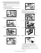

AR-5127 EXTERNAL VIEW AND INTERNAL STRUCTURE 6 - 4
6. PWB unit
7. Section
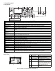
19 Door switch SW24V Front door and side
door open/close
detection
20 2nd right door switch DRS1A Side door open/close
detection
21 2nd cassette paper
pass sensor
PPD1A 2nd cassette paper
pass
22 2nd cassette paper
upper limit detection
sensor
LUD1A 2nd cassette paper
upper limit detection
23 2nd cassette paper
empty sensor
PAP1A 2nd cassette paper
empty detection
24 1st cassette paper
upper limit detection
sensor
LUD1H 1st cassette paper
upper limit detection
25 1st cassette paper
empty sensor
PAP1H 1st cassette paper
empty detection
26 Center tray paper
YES/NO sensor
TRAYPAPER
Center tray paper
YES/NO detection
27 1st cassette paper
pass sensor
PIN 1st cassette paper
pass
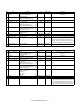
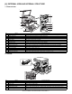
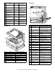
No. Name Function and operation
1 Inverter PWB Copy lamp control
2 CCD PWB For image scanning (read)
3 Option connector PWB
4 MCU PWB Main unit control
5 Tray interface PWB 2nd tray control
6 KEY/LED PWB (right side) For the copy operation
7 LCD back light PWB LCD control
8 KEY/LED PWB (left side) For the FAX operation
9 Power source PWB AC power input/DC voltage
control
No. Name Code
Function and
operation
1
2
3
4
5
6
7
8
11
10
9
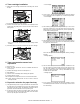
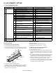
No. Name Function and operation
1 Copy lamp Image radiation lamp
2 Copy lamp unit Operates in synchronization with
2nd/3rd mirror unit to radiate
documents sequentially.
3 LSU unit Converts image signals into laser
beams to write on the dum.
4 Lens unit Reads images with the lens and
the CCD.
5 MC holder unit Supplies negative charges evenly
on the drum.
6 Paper exit roller Paper exit roller
7 Transport roller Paper transport roller
8 Upper heat roller Fuses toner on paper.
(with the teflon roller)
9 Lower heat roller Fuses toner on paper.
(with the silicone rubber roller)
10 Drum unit Forms images.
11 DUP transport follower
roller
Duplex paper transport
12 DUP transport roller Duplex paper transport
13 Transport roller Transfer images on the drum onto
paper.
14 Resist roller Synchronize the paper lead edge
with the image lead edge.
15 Manual feed tray Manual feed paper tray
16 Manual paper feed roller Picks up papers in manual paper
feed port.
17 Manual feed transport
roller
Transports paper from the manual
paper feed port.
18 1st cassette pick-up
roller
Picks up paper from the cassette.
19 1st cassette paper feed
roller
Transports the picked up paper to
RESIST section.
20 2nd cassette pick-up
roller
Picks up paper from the cassette.
21 2nd cassette paper feed
roller
Transports the picked up paper to
RESIST section.
22 MG roller Puts toner on the OPC drum.
23 2nd/3rd mirror unit Reflects the images from the copy
lamp unit to the lens unit.
21
22
23
12 3 4 5
6
7
8
9
10
12
13
14
15
16
17
18
19
20
11