
Owner manual

AR-5127 ADJUSTMENTS 7 - 1
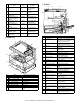
[7] ADJUSTMENTS, SETTING
1. List of adjustment items
2. Copier adjustment
A. Process section
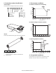
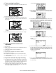
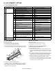
(1) Developing doctor gap adjustment
1) Loosen the developing doctor fixing screw A.
2) Insert a thickness gauge of 1.5mm to the three positions at 20mm
and 150mm from the both ends of the developing doctor as shown.
3) Tighten the developing doctor fixing screw.
4) Check the clearance of the developing doctor. If it is within the
specified range, then fix the doctor fixing screw with screw lock.
∗
When inserting a thickness gauge, be careful not to scratch the
developing doctor and the MG roller.
<Adjustment specification>
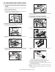
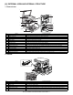
(2) MG roller main pole position adjustment
1) Put the developing unit on a flat surface.
2) Tie a needle or pin on a string.
3) Hold the string and bring the needle close to the MG roller horizon-
tally. (Do not use paper clip, which is too heavy to make a correct
adjustment.) (Put the developing unit horizontally for this adjust-
ment.)
4) Do not bring the needle into contact with the MG roller, but bring it
to a position 2 or 3mm apart from the MG roller. Mark the point on
the MG roller which is on the extension line from the needle tip.
5) Measure the distance from the marking position to the top of the
doctor plate of the developing unit to insure that it is 18mm.
If the distance is not within the specified range, loosen the fixing
screw A of the main pole adjustment plate, and move the adjust-
ment plate in the arrow direction to adjust.
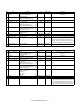
Section Adjustment item Adjustment procedure/SIM No.
A Process section (1) Developing doctor gap adjustment Developing doctor gap adjustment
(2) MG roller main pole position adjustment MG roller main pole position adjustment
(3) Developing bias voltage adjustment SIM8-1
(4) Grid bias voltage adjustment (High mode) SIM8-2
(5) Grid bias voltage adjustment (Low mode) SIM8-3
B Mechanism section (1) OC image lead edge position/Sub scanning
magnification ratio/Original offset auto adjustment
SIM48-3
(2) Print start position adjustment SIM50-5
(3) SPF image lead edge position adjustment SIM50-6
(4) Rear edge void adjustment SIM50-1-6
(5) Paper off center adjustment SIM50-10
(6) Left edge void area adjustment SIM50-1-8
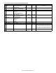
(7) Main scanning direction (FR direction) distortion
balance adjustment
No. 2/3 mirror base unit installing position
adjustment
Copy lamp unit installing position adjustment
(8) Sub scanning direction (scanning direction)
distortion adjustment
Winding pulley position adjustment
(9) Main scanning direction (FR direction) distortion
adjustment
Rail height adjustment
(10) Main scanning direction (FR direction)
magnification ratio adjustment
SIM48-1-1, 48-1-2
(11) Sub scanning direction (scanning direction)
magnification ratio adjustment
a OC mode in copying (SIM 48-1-3)
b RSPF sub scanning direction magnification ratio
(SIM48-1-4, 48-1-5)
(12) Off center adjustment (SPF mode) SIM50-12
(13) OC (SPF) open/close detection position adjustment SIM41-3
(14) Original sensor adjustment SIM41-2, 41-4
(15) SPF white correction pixel position adjustment
(required in an SPF model when replacing the lens
unit)
SIM63-7
(16) SPF scan position auto adjustment SIM53-8, SIM46-20, SIM50-6
C Image density
(exposure) adjustment
(1) Copy mode SIM46-2
20mm
10mm
150mm
10mm
20mm
F
C
R
DG:1.5
+0.1
- 0.15
DG:1.5
+0.1
- 0.15
DG:1.55
+0.15
- 0.2
Developing doctor gap
F/R both ends (20mm from the both ends):1.5
+0.1mm
-0.15mm
C (Center)(150mm from the both ends): 1.55
+0.15mm
-0.2mm