
Specifications

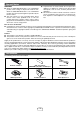
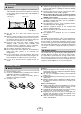


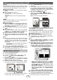

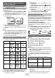

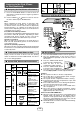
Table Of Contents
- Special Notes
- Accessories
- Precaution
- Remote control
- System connections
- General control
- Wi-Fi network Setup for AirPlay / DLNA
- Listening to the iPod, iPhone or iPad
- Listening to a CD or MP3/WMA disc
- Listening to USB mass storage device/MP3 player
- Advanced USB playback
- Listening to the radio
- Using the Radio Data System (RDS)
- Setting the clock (Remote control only)
- Timer and sleep operation (Remote control only)
- Enhancing your system
- Troubleshooting chart
- Maintenance
- Specifications

3
Aerial connection■
Supplied FM aerial:
Connect the FM aerial wire to the FM 75 OHMS socket
and position the FM aerial wire in the direction where the
strongest signal can be received.
External FM aerial:
Use an external FM aerial (75 ohms coaxial cable) for
better reception. When an external FM aerial is used,
disconnect the supplied FM aerial wire.
Supplied AM loop aerial:
Connect the AM loop aerial to the AM and earth (GND)
terminals. Position the AM loop aerial for optimum
reception. Place the AM loop aerial on a shelf, etc., or
attach it to a stand or a wall with screws (not supplied).
Installing the AM loop aerial:
<Assembling> <Attaching to the wall>
Wall Screws
(not supplied)
Notes:
Placing the aerial on the unit or near the AC power
lead may cause noise pickup. Place the aerial away
from the unit for better reception.
●
AC power connection■
After checking all the connections have been made correctly,
plug the AC power lead of this unit into the wall socket.
Note:
Unplug the AC power lead from the wall socket if the unit
will not be in use for a prolonged period of time.
Network Stand-by (demonstration) mode■
The rst time the unit is plugged in, the unit will
enter the Network Stand-by (demonstration) mode.
“NETWORK ST-BY” will be displayed (refer page 7)
To cancel the Network Stand-by (demonstration)
mode, press the DEMO button (remote control) during
power stand-by mode. The unit will enter the low
power consumption mode.
If iPod or iPhone is docked, the unit will begin charging.
“Charge Mode” will be displayed. Network Stand-by
(demonstration) mode is invalid during charge mode.
To return to the Network Stand-by (demonstration)
mode, press the DEMO button again.
●
●
●
●
Make sure to unplug the AC power lead before making any connections.
System connections
Wall socket
(AC 220 - 240 V ~ 50/60 Hz)
External FM aerial for better
reception (not supplied)
FM aerial
AM loop aerial