
Installation Manual


E
. Let the socket hang
freely. See Figure B.
Recessed Ceiling Fixture Capability
This Sharp " round luminaire can be installed in select re-
cessed " round ceiling fixtures.
Warning: Risk of Electric Shock – Use only compatible
recessed fixtures that are listed on the specification sheets
available for download at www.sharpledlighting.com. All
listed compatible recessed fixtures should be installed per the
manufacturer’s installation instructions and should be in strict
conformance with local building and electrical codes.
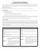
TYPICAL RECESSED
CEILING FIXTURE
SOCKET
MOUNTING
BRACKET
SOCKET
FIGURE A
Unpack the product and remove all packing material. This
product comprises of two assemblies, the luminaire and the
socket adaptor.
InstallatIon
. Turn power o.
. Remove lamp and reflector from the ceiling fixture for
retrofit if applicable. Detach the socket from the socket
mounting bracket and remove mounting bracket.
. Attach socket adaptor
into socket.
See Figure C.
. Connect the other end of the
socket adaptor to the connector on
top of the luminaire. A positive lock
will secure the two connectors.
See Figure D.
DO NOT SUSPEND LUMINAIRE
FROM SOCKET ADAPTOR.
. Compress the two
torsion springs together,
release them so that each
one seats into the side
brackets located in the
sidewall of the ceiling
fixture. See Figure E.
. Tuck the wiring and connector back into the ceiling fixture.
. Carefully push the luminaire
up into the ceiling fixture until
flush with the ceiling. See
Figure F.
. Restore power to ensure
operation.
CautIon – safety statements
Qualified licensed professionals should perform all
installation work. Installation must be completed in strict
conformance with local building and electrical codes.
Do not dis-assemble the luminaire.
Do not remove or attempt to operate without lens cover
over LED.
Do not handle energized luminaires.
Warning – Do not expose wiring to edges of metal to
prevent damage.
Warning – For removal of luminaire, turn o power. Allow
luminaire to cool before handling. Reverse process of
installation for removal.
SOCKET
ADAPTOR
FIGURE C
POSITIVE LOCK
CONNECTORS
FIGURE D
FIGURE B
FIGURE F
FIGURE E
TYPICAL SIDE BRACKET IN
RECESSED CEILING FIXTURE
COMPRESS
TO INSTALL
ENGAGE
TORSION
SPRINGS
INTO SIDE
BRACKETS
TORSION
SPRINGS
ROUND DOWN LIGHT INSTALLATION INSTRUCTIONS