Manual WAGO-I/O-SYSTEM 750 Serial Interface RS-232 / RS-485 750-652 Configurable Version 1.3.
WAGO-I/O-SYSTEM 750 750-652 Serial Interface RS-232 / RS-485 © 2014 by WAGO Kontakttechnik GmbH & Co. KG All rights reserved. WAGO Kontakttechnik GmbH & Co. KG Hansastraße 27 D-32423 Minden Phone: Fax: +49 (0) 571/8 87 – 0 +49 (0) 571/8 87 – 1 69 E-Mail: info@wago.com Web: http://www.wago.com Technical Support Phone: Fax: +49 (0) 571/8 87 – 5 55 +49 (0) 571/8 87 – 85 55 E-Mail: support@wago.
WAGO-I/O-SYSTEM 750 750-652 Serial Interface RS-232 / RS-485 Table of Contents 3 Table of Contents 1 1.1 1.2 1.3 1.4 1.5 Notes about this Documentation ................................................................. 6 Validity of this Documentation ................................................................. 6 Copyright................................................................................................... 6 Symbols ......................................................................
Table of Contents 5.1.5 5.1.6 5.2 WAGO-I/O-SYSTEM 750 750-652 Serial Interface RS-232 / RS-485 RS-422 Operating Mode..................................................................... 37 DMX Operating Mode ....................................................................... 38 Data Exchange Operating Mode ............................................................. 38 6 Mounting..................................................................................................... 40 6.
WAGO-I/O-SYSTEM 750 750-652 Serial Interface RS-232 / RS-485 10.2.2 10.2.3 10.2.4 10.2.5 Table of Contents 5 Special Conditions for Safe Use (ATEX Certificate TÜV 12 ATEX 106032 X) ........................................................................................... 72 Special Conditions for Safe Use (IEC-Ex Certificate TUN 09.0001 X)73 Special Conditions for Safe Use (IEC-Ex Certificate IECEx TUN 12.0039 X) ..........................................................................................
1 Notes about this Documentation WAGO-I/O-SYSTEM 750 750-652 Serial Interface RS-232 / RS-485 Notes about this Documentation Always retain this documentation! This documentation is part of the product. Therefore, retain the documentation during the entire service life of the product. Pass on the documentation to any subsequent user. In addition, ensure that any supplement to this documentation is included, if necessary. 1.
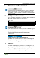
WAGO-I/O-SYSTEM 750 750-652 Serial Interface RS-232 / RS-485 1.3 Notes about this Documentation 7 Symbols Personal Injury! Indicates a high-risk, imminently hazardous situation which, if not avoided, will result in death or serious injury. Personal Injury Caused by Electric Current! Indicates a high-risk, imminently hazardous situation which, if not avoided, will result in death or serious injury.
Notes about this Documentation WAGO-I/O-SYSTEM 750 750-652 Serial Interface RS-232 / RS-485 Additional Information: Refers to additional information which is not an integral part of this documentation (e.g., the Internet). Manual Version 1.3.
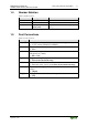
WAGO-I/O-SYSTEM 750 750-652 Serial Interface RS-232 / RS-485 1.4 Notes about this Documentation 9 Number Notation Table 2: Number Notation Number Code Decimal Hexadecimal Binary 1.5 Example 100 0x64 '100' '0110.0100' Note Normal notation C notation In quotation marks, nibble separated with dots (.) Font Conventions Table 3: Font Conventions Font Type Indicates italic Names of paths and data files are marked in italic-type. e.g.: C:\Programme\WAGO-I/O-CHECK Menu items are marked in bold letters.
Important Notes 2 WAGO-I/O-SYSTEM 750 750-652 Serial Interface RS-232 / RS-485 Important Notes This section includes an overall summary of the most important safety requirements and notes that are mentioned in each individual section. To protect your health and prevent damage to devices as well, it is imperative to read and carefully follow the safety guidelines. 2.1 Legal Bases 2.1.1 Subject to Changes WAGO Kontakttechnik GmbH & Co.
WAGO-I/O-SYSTEM 750 750-652 Serial Interface RS-232 / RS-485 Important Notes 11 Appropriate housing (per 94/9/EG) is required when operating the WAGO-I/OSYSTEM 750 in hazardous environments. Please note that a prototype test certificate must be obtained that confirms the correct installation of the system in a housing or switch cabinet. 2.1.
2.2 Important Notes WAGO-I/O-SYSTEM 750 750-652 Serial Interface RS-232 / RS-485 Safety Advice (Precautions) For installing and operating purposes of the relevant device to your system the following safety precautions shall be observed: Do not work on devices while energized! All power sources to the device shall be switched off prior to performing any installation, repair or maintenance work.
WAGO-I/O-SYSTEM 750 750-652 Serial Interface RS-232 / RS-485 Important Notes 13 Do not use any contact spray! Do not use any contact spray. The spray may impair contact area functionality in connection with contamination. Do not reverse the polarity of connection lines! Avoid reverse polarity of data and power supply lines, as this may damage the devices involved.
3 Device Description WAGO-I/O-SYSTEM 750 750-652 Serial Interface RS-232 / RS-485 Device Description The I/O module 750-652 (Serial Interface RS-232 / RS-485) allows the optional connection of devices with a RS-485, RS-422 or RS-232 interface. It also provides gateways between the serial interface and the fieldbus systems supported by the WAGO-I/O-SYSTEM 750. No higher protocol level is required by the module. Communication to the associated fieldbus master is completely transparent.
WAGO-I/O-SYSTEM 750 750-652 Serial Interface RS-232 / RS-485 Device Description 15 The I/O module can be configured as a DMX sender with a baud rate of 250 kBits/s. This function is available with firmware version 03 or higher. The wiring to the communication partner takes place in RS-232 mode via the TxD, RxD connections, if necessary RTS/CTS and ground and in the RS-485/ RS-422 mode via the connections A, B, X, Y, and ground.
Device Description WAGO-I/O-SYSTEM 750 750-652 Serial Interface RS-232 / RS-485 The 750-652 module can be used with the fieldbus couplers and controllers of the WAGO-I/O-SYSTEM 750 of the specified version or higher listed in the “Compatibility list” table.
WAGO-I/O-SYSTEM 750 750-652 Serial Interface RS-232 / RS-485 Table 4: Compatibility List 750-0652 Fieldbus Bus System couplers/controllers Programmable fieldbus controller I/O-IPC* KNX Device Description Item No. 750-837 750-838 758-870/ 000-112 758-875/ 000-112 750-849 Programmable fieldbus controller BACnet Programmable 750-830 fieldbus controller * Also available via 2 ETHERNET interfaces Firmware status 14 14 05 05 04 03 Other fieldbus couplers/controllers on request. Manual Version 1.3.
3.1 Device Description WAGO-I/O-SYSTEM 750 750-652 Serial Interface RS-232 / RS-485 View Figure 1: View Table 5: Legend for Figure “View” Pos.
WAGO-I/O-SYSTEM 750 750-652 Serial Interface RS-232 / RS-485 3.2 Connectors 3.2.1 Data Contacts/Internal Bus Device Description 19 Communication between the fieldbus coupler/controller and the I/O modules as well as the system supply of the I/O modules is carried out via the internal bus. It is comprised of 6 data contacts, which are available as self-cleaning gold spring contacts.
Device Description 3.2.2 WAGO-I/O-SYSTEM 750 750-652 Serial Interface RS-232 / RS-485 Power Jumper Contacts/Field Supply Risk of injury due to sharp-edged blade contacts! The blade contacts are sharp-edged. Handle the I/O module carefully to prevent injury. The I/O module 750-652 has 2 self-cleaning power jumper contacts that supply and transmit power for the field side. The contacts on the left side of the I/O module are designed as blade contacts and those on the right side as spring contacts.
WAGO-I/O-SYSTEM 750 750-652 Serial Interface RS-232 / RS-485 Device Description 21 Use supply modules for ground (earth)! The I/O module has no power jumper contacts for receiving and transmitting the earth potential. Use a supply module when an earth potential is needed for the subsequent I/O modules. Manual Version 1.3.
Device Description 3.2.3 WAGO-I/O-SYSTEM 750 750-652 Serial Interface RS-232 / RS-485 CAGE CLAMP® Connectors Use shielded signal lines! Only use shielded signal lines for analog signals and I/O modules which are equipped with shield clamps. Only then can you ensure that the accuracy and interference immunity specified for the respective I/O module can be achieved even in the presence of interference acting on the signal cable.
WAGO-I/O-SYSTEM 750 750-652 Serial Interface RS-232 / RS-485 3.3 Device Description 23 Display Elements Figure 5: Display Elements Table 8: Legend for Figure “Display Elements” LED Designation Status Green A Function Red OFF Green B 1) 2) 3) 4) 5) Manual Version 1.3.
3.4 Device Description WAGO-I/O-SYSTEM 750 750-652 Serial Interface RS-232 / RS-485 Operating Elements The I/O module 750-652 has no operating elements. 3.5 Schematic Diagram Figure 6: Schematic Diagram Manual Version 1.3.
WAGO-I/O-SYSTEM 750 750-652 Serial Interface RS-232 / RS-485 3.6 Technical Data 3.6.1 Device Data Device Description 25 Table 9: Technical Data – Device Data Width Height (from upper edge of DIN 35 rail) Length Weight Degree of protection 3.6.2 12 mm 64 mm 100 mm approx. 50 g IP20 Supply Table 10: Technical Data – Supply Power supply Current consumption (internal) Current via power jumper contacts max. Isolation (peak value) 3.6.3 via system voltage internal bus (5 VDC) max.
Device Description 3.6.4 WAGO-I/O-SYSTEM 750 750-652 Serial Interface RS-232 / RS-485 Interface Table 12: Technical Data – Interface Number of interfaces Input resistance of the receiver RS-485/RS-422 Isolation 3.6.
WAGO-I/O-SYSTEM 750 750-652 Serial Interface RS-232 / RS-485 3.7 Device Description 27 Approvals The following approvals have been granted to the basic version and all variants of 750-652 I/O modules: Conformity Marking CULUS UL508 The following Ex approvals have been granted to 750-652 I/O modules: TÜV 07 ATEX 554086 X I M2 Ex d I Mb II 3 G Ex nA IIC T4 Gc II 3 D Ex tc IIIC T135°C Dc Ambient temperature range: 0 °C ≤ Ta ≤ +60 °C IECEx TUN 09.
Device Description WAGO-I/O-SYSTEM 750 750-652 Serial Interface RS-232 / RS-485 The following ship approvals have been granted to 750-652 I/O modules: ABS (American Bureau of Shipping) Federal Maritime and Hydrographic Agency BV (Bureau Veritas) DNV (Det Norske Veritas) Class B GL (Germanischer Lloyd) Cat. A, B, C, D (EMC 1) KR (Korean Register of Shipping) LR (Lloyd’s Register) Env. 1, 2, 3, 4 NKK (Nippon Kaiji Kyokai) RINA (Registro Italiano Navale) Manual Version 1.3.
WAGO-I/O-SYSTEM 750 750-652 Serial Interface RS-232 / RS-485 3.8 Device Description Standards and Guidelines All variations of 750-652 I/O modules meet the following requirements on emission and immunity of interference: EMC CE-Immunity to interference Manual Version 1.3.0 acc.
4 Process Image WAGO-I/O-SYSTEM 750 750-652 Serial Interface RS-232 / RS-485 Process Image Mapping of process data in the process image of fieldbus systems The representation of the I/O modules’ process data in the process image depends on the fieldbus coupler/controller used.
WAGO-I/O-SYSTEM 750 750-652 Serial Interface RS-232 / RS-485 Table 15: Control Byte C0 Bit 7 Bit 6 Bit 5 RC TR RA IR SC OL 0 OL1 OL2 RC OL2 OL1 TA RR IA IL0 IL1 IL2 BUF_F RC BUF_F 0 OL4 OL5 0 Manual Version 1.3.
Process Image WAGO-I/O-SYSTEM 750 750-652 Serial Interface RS-232 / RS-485 Table 18: Status Byte S1 Bit 7 Bit 6 EOV EFR Bit 5 Bit 4 Bit 3 Bit 2 Bit 1 Bit 0 EPR CTS BUF_E IL5 IL4 IL3 IL3 Input length (number of characters received that are available in the input data, bit 3) IL4 Input length (number of characters received that are available in the input data, bit 4) IL5 Input length (number of characters received that are available in the input data, bit 5) BUF_E Buffer empty (message:
WAGO-I/O-SYSTEM 750 750-652 Serial Interface RS-232 / RS-485 Table 20: Control Byte C0 Bit 7 Bit 6 Bit 5 RC IR X Table 21: Status Byte S0 Bit 7 Bit 6 RC LGT CHK RCVT Bit 4 Bit 3 Bit 2 Bit 1 Bit 0 X X IR X X X Bit 5 Bit 4 Bit 3 Bit 2 Bit 1 Bit 0 X X RCVT CHK 0 LGT The length of the telegram last received does not match the PI size. Wrong checksum received. No error-free transmission of the opposite side was received for >= 200 ms (timeout).
Function Description WAGO-I/O-SYSTEM 750 750-652 Serial Interface RS-232 / RS-485 5 Function Description 5.1 Operating Modes for Serial Transmission In den In the operating modes for serial transmission, the I/O module allows communication with serial devices via RS-232, RS-485, RS-422 or DMX. The I/O module operates in these modes as a link between one of these standardized interfaces to the one side and the application or controller to the other side.
WAGO-I/O-SYSTEM 750 750-652 Serial Interface RS-232 / RS-485 5.1.1.1 Function Description 35 Continuous Transmission The I/O module can be set either to transmit data in the output buffer to the serial interface immediately or to start the transmission process only after released by the application.
Function Description WAGO-I/O-SYSTEM 750 750-652 Serial Interface RS-232 / RS-485 The time period after which the I/O module starts data transmission can be defined using the "Continuous Receive Timeout" parameter. Because the duration of the transfer of any amount of data depends on the baud rate setting, number of data and stop bits and the parity, an absolute time specification is not feasible.
WAGO-I/O-SYSTEM 750 750-652 Serial Interface RS-232 / RS-485 5.1.3.3 Function Description 37 Flow Control Using RTS/CTS, RTS with Lead/Follow-on Time With firmware version 03 or higher, the I/O module allows RTS/CTS for communication with serial devices that only support a half-duplex connection. This is important, for example, for communication with some telecontrol modems. If this type of flow control is activated, the I/O module sets RTS while it transmits data to the serial interface.
Function Description 5.1.6 WAGO-I/O-SYSTEM 750 750-652 Serial Interface RS-232 / RS-485 DMX Operating Mode The DMX operating mode is also available with firmware version 03 or higher. In this mode, the I/O module functions as a DMX sender and allows up to 31 nodes to be connected. The transmission channel is based on RS-485 physics with a transmission rate of 250 kBaud, as well as 1 start and 2 stop bits. In this mode, no further settings are possible.
WAGO-I/O-SYSTEM 750 750-652 Serial Interface RS-232 / RS-485 Function Description 39 Figure 7: Internal Structure If two I/O modules are connected together in this mode, each I/O module transmits the data bytes of the process output image cyclically to the I/O module on the opposite side. Received data bytes of the process output image on the opposite side are again represented as data bytes in the process image of the local I/O module. The sequence of data bytes remains unchanged during transmission.
Mounting 6 Mounting 6.1 Mounting Sequence WAGO-I/O-SYSTEM 750 750-652 Serial Interface RS-232 / RS-485 Fieldbus couplers/controllers and I/O modules of the WAGO-I/O-SYSTEM 750/753 are snapped directly on a carrier rail in accordance with the European standard EN 50022 (DIN 35). The reliable positioning and connection is made using a tongue and groove system. Due to the automatic locking, the individual devices are securely seated on the rail after installation.
WAGO-I/O-SYSTEM 750 750-652 Serial Interface RS-232 / RS-485 6.2 Mounting 41 Inserting and Removing Devices Perform work on devices only if they are de-energized! Working on energized devices can damage them. Therefore, turn off the power supply before working on the devices. 6.2.1 Inserting the I/O Module 1. Position the I/O module so that the tongue and groove joints to the fieldbus coupler/controller or to the previous or possibly subsequent I/O module are engaged.
Mounting 6.2.2 WAGO-I/O-SYSTEM 750 750-652 Serial Interface RS-232 / RS-485 Removing the I/O Module 1. Remove the I/O module from the assembly by pulling the release tab. Figure 10: Removing the I/O Module (Example) Electrical connections for data or power jumper contacts are disconnected when removing the I/O module. Manual Version 1.3.
WAGO-I/O-SYSTEM 750 750-652 Serial Interface RS-232 / RS-485 7 Connect Devices 43 Connect Devices Use shielded signal lines! Only use shielded signal lines for analog signals and I/O modules which are equipped with shield clamps. Only then can you ensure that the accuracy and interference immunity specified for the respective I/O module can be achieved even in the presence of interference acting on the signal cable. 7.
Connect Devices WAGO-I/O-SYSTEM 750 750-652 Serial Interface RS-232 / RS-485 Figure 11: Connecting a Conductor to a CAGE CLAMP® 7.2 Connection Examples 7.2.1 RS-232 Operating Mode Figure 12: Point-to-Point Connection Operating Mode RS-232 with RTS/CTS Data Flow Control In the RS-232 operating mode (point-to-point connection), terminal resistors are not necessary. The cable length can be up to 40 m due to the maximum allowable cable capacitance of 1500 pF.
WAGO-I/O-SYSTEM 750 750-652 Serial Interface RS-232 / RS-485 7.2.2 Connect Devices 45 RS-485 Operating Mode Figure 13: Bus Connection RS-485 Operating Mode, Half-Duplex In the RS-485 operating mode (bus connection), a twisted-pair cable should be used at least for larger cable lengths or higher transmission rates. The ends of the cable should be terminated with a terminal resistor.
Connect Devices WAGO-I/O-SYSTEM 750 750-652 Serial Interface RS-232 / RS-485 Figure 14: Bus Connection RS-485 Operating Mode with Biasing Network, Half-Duplex With the use of the biasing resistors, it is guaranteed in this case that all receiver inputs A have the voltage difference of more than 200 mV to the inputs B if no transmitter is active. The oscillations of the receiver that can cause defective reception are thus prevented.
WAGO-I/O-SYSTEM 750 750-652 Serial Interface RS-232 / RS-485 7.2.3 Connect Devices 47 RS-422 Operating Mode Figure 15: Bus Connection RS-422 Operating Mode For the RS-422 operating mode (point-to-point connection), the bus ends (at least for longer line lengths and greater baud rates) should be terminated with a terminal resistor. Generally a passive resistance is used by connecting the signal lines via one 100 ... 120 Ω resistor apiece to both bus ends.
Connect Devices 7.2.5 WAGO-I/O-SYSTEM 750 750-652 Serial Interface RS-232 / RS-485 Data Exchange Mode Figure 16: Point-to-Point Connection Between Two Nodes In this mode, the contacts of the I/O modules to connect are connected to each other crosswise. In the Data Exchange operating mode (point-to-point connection), a twisted-pair cable should be used at least for larger cable lengths. Two wire pairs and one ground wire are required.
WAGO-I/O-SYSTEM 750 750-652 Serial Interface RS-232 / RS-485 Commissioning 8 Commissioning 8.1 Configuration and Parameterization with WAGO-I/O-CHECK 49 The serial interface module is configured with the WAGO-I/O-CHECK software (version 3.3 or higher, WAGO-I/O-CHECK version 3.5.3 is required for firmware version 03 or higher). The software's basic functionality is described separately in the WAGO-I/O-CHECK documentation.
Commissioning WAGO-I/O-SYSTEM 750 750-652 Serial Interface RS-232 / RS-485 The parameter dialog is divided into the following areas: • Title bar with item and item number of the selected I/O module, info area with item number, designation, and version number and version date of the I/O module, • • • Toolbar (1), Parameter range (2) and Status bar (3). Status reports are output in the status display in the lower area of the configuration dialog. 8.1.
WAGO-I/O-SYSTEM 750 750-652 Serial Interface RS-232 / RS-485 Commissioning 51 Table 22: Toolbar Button Function Description Configuration Sets the process image size. Help 8.1.3 Opens the WAGO-I/O-CHECK online help. Process Image Size To make settings on the "PI Mapping" (process image mapping) page, the process image size of the master must be set first. Use the [Configuration] button on the toolbar to open the dialog for entering the process image size.
Commissioning WAGO-I/O-SYSTEM 750 750-652 Serial Interface RS-232 / RS-485 With the [Default] button, you select the default setting for this I/O module. With the [Apply] button, you then transfer the parameters to the non-volatile memory of the I/O module. With the [Close] button, you close the configuration dialog without transferring any changed parameters to the non-volatile memory of the I/O module. 8.1.
WAGO-I/O-SYSTEM 750 750-652 Serial Interface RS-232 / RS-485 Commissioning 53 Table 24: Parameter Range Selection box Possible settings 3) Switchover Time RS-485 100 µs* / 2 Characters / 4 Characters Continuous Receive Timeout 2 Characters* / 4 Characters * Default setting 1) The setting is relevant for the operating mode RS-232/RS-422, full-duplex. 2) The setting is relevant for the operating mode RS-232. 3) The setting is relevant for the operating mode RS-485, half-duplex.
Commissioning WAGO-I/O-SYSTEM 750 750-652 Serial Interface RS-232 / RS-485 To change settings in the serial I/O module, adjust the values in the configuration area. Changed settings are marked with a change symbol (pen symbol) in order to indicate that these values no longer match the values originally queried by the module. To transfer the new values to the I/O module, click the [Write] button. You can also put the I/O module into another operating mode.
WAGO-I/O-SYSTEM 750 750-652 Serial Interface RS-232 / RS-485 Commissioning 55 Transmit data: • TR = TA: Writing of the characters to be transmitted in output bytes D0 to Dn • Number of characters to be transmitted is specified in OL0 to OL5 • Inversion and output of TR • Transfer to the output buffer takes place when TR = TA Receive data: • RR ≠ RA: in input byte 0 to n characters are available • Number of characters received is specified in IL0 to IL5 • Reading out of the characters in IL0 to IL5 • Inve
Commissioning WAGO-I/O-SYSTEM 750 750-652 Serial Interface RS-232 / RS-485 Control requests data exchange: Table 27: Data Exchange Control byte 0 '0000.0000' Control byte 1 '0000.0000' Output byte 0 XX Output byte 1 XX The IA bit is reset by the I/O module. Table 28: I/O Module Is Ready Status byte 0 Status byte 1 '0XXX. X0XX' '0XXX. 1XXX' 8.3.3 Input byte 0 XX Input byte 1 XX The I/O module is ready.
WAGO-I/O-SYSTEM 750 750-652 Serial Interface RS-232 / RS-485 8.3.4 Commissioning 57 Receiving the Character String "WAGO" As soon as RA ≠ RR, characters are available in the input byte. Table 32: Output Process Image Control byte 0 Control byte 1 '0XXX XX0X '0XXX.XXXX' Table 33: Receive Data Status byte 0 Status byte 1 0-xxx X (00x) '0XXX. 1XXX' '0XX1. 001X' '0XXX. 1XXX' Output byte 0 XX Input byte 0 XX Input byte 1 XX "W" "A" Output byte 1 XX There are no receive data available.
Commissioning WAGO-I/O-SYSTEM 750 750-652 Serial Interface RS-232 / RS-485 Table 37: Transmission of a Block of One to 512 Bytes Control byte 0 Control byte 1 '0110.1001' '0XXX. X101' Controller fills the output buffer with 46 bytes and set bit 3 (SC) of the control byte 0 for the start of the transmission. Status byte 0 Status byte 1 '0XXX.X0X1' '0000. 1XXX' I/O module confirms the acceptance of the data. Control byte 0 Control byte 1 '0110.1000' '0XXX.
WAGO-I/O-SYSTEM 750 750-652 Serial Interface RS-232 / RS-485 Commissioning 59 Table 38: Transmission of a Block of More than 512 Bytes*) Control byte 0 Control byte 1 '0110.1001' '0XXX. X101' Status byte 0 '0XXX.X0X1' Control byte 0 '0110.1000' Status byte 0 '0XXX.X0X0' Status byte 1 '0000. 1XXX' Control byte 1 '0XXX. X101' Status byte 1 '0XXX. 0XXX' Control byte 0 '0110.1001' Control byte 1 '0XXX. X101' Status byte 0 '0XXX.X0X1' Status byte 0 '0XXX.X0X1' Status byte 1 '0000.
Commissioning WAGO-I/O-SYSTEM 750 750-652 Serial Interface RS-232 / RS-485 8.3.6 DMX Application Example 8.3.6.1 Operation with Deactivated Continuous Send In this mode, the I/O module only transmits the data for a limited number of DMX channels according to the set size of the process image (see table “Process data in the DMX operating mode without continuous send”). Higher refresh rates are then possible.
WAGO-I/O-SYSTEM 750 750-652 Serial Interface RS-232 / RS-485 8.3.7 Commissioning 61 Data Exchange Operating Mode Application Example In the “Data Exchange” operating mode, the I/O module monitors process data exchange with the partner module. If the connection is interrupted for 200 ms or more, it generates a diagnosis in the status byte. This monitoring only takes into account if there is a connection between the I/O modules.
Diagnostics WAGO-I/O-SYSTEM 750 750-652 Serial Interface RS-232 / RS-485 9 Diagnostics 9.1 Serial Operating Modes Table 40: Diagnostics, Serial Operating Modes Diagnostics Event Input buffer full The I/O module receives data via the serial interface faster than accepted by the application. Output buffer full Parity error Overflow 9.
WAGO-I/O-SYSTEM 750 750-652 Serial Interface RS-232 / RS-485 10 Use in Hazardous Environments 63 Use in Hazardous Environments The WAGO-I/O-SYSTEM 750 (electrical equipment) is designed for use in Zone 2 hazardous areas. The following sections include both the general identification of components (devices) and the installation regulations to be observed.
Use in Hazardous Environments WAGO-I/O-SYSTEM 750 750-652 Serial Interface RS-232 / RS-485 10.1 Marking Configuration Examples 10.1.1 Marking for Europe According to ATEX and IEC-Ex Figure 21: Side Marking Example for Approved I/O Modules According to ATEX and IECEx Figure 22: Text Detail – Marking Example for Approved I/O Modules According to ATEX and IECEx. Manual Version 1.3.
WAGO-I/O-SYSTEM 750 750-652 Serial Interface RS-232 / RS-485 Use in Hazardous Environments 65 Table 42: Description of Marking Example for Approved I/O Modules According to ATEX and IECEx Printing on Text TÜV 07 ATEX 554086 X IECEx TUN 09.0001 X Dust II 3D Ex tc Dc IIIC T 135°C Mining I M2 Ex d Mb I Gases II 3G Ex nA Gc nC Gc IIC T4 Manual Version 1.3.
Use in Hazardous Environments WAGO-I/O-SYSTEM 750 750-652 Serial Interface RS-232 / RS-485 Figure 23: Side Marking Example for Approved Ex i I/O Modules According to ATEX and IECEx. Figure 24: Text Detail – Marking Example for Approved Ex i I/O Modules According to ATEX and IECEx. Manual Version 1.3.
WAGO-I/O-SYSTEM 750 750-652 Serial Interface RS-232 / RS-485 Use in Hazardous Environments 67 Table 43: Description of Marking Example for Approved Ex i I/O Modules According to ATEX and IECEx Inscription Text TÜV 07 ATEX 554086 X IECEx TUN 09.0001X TÜV 12 ATEX 106032 X IECEx TUN 12.0039 X Dust II 3(1)D 3(2)D Ex tc Dc [ia Da] [ib Db] IIIC T 135°C Mining I M2 (M1) Ex d Mb [ia Ma] I Manual Version 1.3.
Use in Hazardous Environments WAGO-I/O-SYSTEM 750 750-652 Serial Interface RS-232 / RS-485 Table 43: Description of Marking Example for Approved Ex i I/O Modules According to ATEX and IECEx Gases II 3(1)G 3(2)G Ex nA Gc [ia Ga] [ia Gb] IIC T4 Equipment group: All except mining Category 3 (Zone 2) equipment containing a safety device for a category 1 (Zone 0) equipment Category 3 (Zone 2) equipment containing a safety device for a category 2 (Zone 1) equipment Explosion protection mark Type of prot
WAGO-I/O-SYSTEM 750 750-652 Serial Interface RS-232 / RS-485 10.1.2 Use in Hazardous Environments Marking for America According to NEC 500 Figure 25: Side Marking Example for I/O Modules According to NEC 500 Figure 26: Text Detail – Marking Example for Approved I/O Modules According to NEC 500 Table 44: Description of Marking Example for Approved I/O Modules According to NEC 500 Printing on Text CL I DIV 2 Grp. ABCD Op temp code T4 Manual Version 1.3.
Use in Hazardous Environments 10.2 WAGO-I/O-SYSTEM 750 750-652 Serial Interface RS-232 / RS-485 Installation Regulations For the installation and operation of electrical equipment in hazardous areas, the valid national and international rules and regulations which are applicable at the installation location must be carefully followed. Manual Version 1.3.
WAGO-I/O-SYSTEM 750 750-652 Serial Interface RS-232 / RS-485 10.2.1 Use in Hazardous Environments 71 Special Conditions for Safe Use (ATEX Certificate TÜV 07 ATEX 554086 X) 1. 2. 3. 4. 5. 6. 7. Manual Version 1.3.0 For use as Gc- or Dc-apparatus (in zone 2 or 22) the Field bus Independent I/O Modules WAGO-I/O-SYSTEM 750-*** shall be erected in an enclosure that fulfils the requirements of the applicable standards (see the marking) EN 60079-0, EN 60079-11, EN 60079-15 and EN 60079-31.
Use in Hazardous Environments 10.2.2 WAGO-I/O-SYSTEM 750 750-652 Serial Interface RS-232 / RS-485 Special Conditions for Safe Use (ATEX Certificate TÜV 12 ATEX 106032 X) 1. 2. 3. 4. For use as Gc- or Dc-apparatus (in zone 2 or 22) the Field bus Independent I/O Modules WAGO-I/O-SYSTEM 750-*** Ex i shall be erected in an enclosure that fulfils the requirements of the applicable standards (see the marking) EN 60079-0, EN 60079-11, EN 60079-15 and EN 60079-31.
WAGO-I/O-SYSTEM 750 750-652 Serial Interface RS-232 / RS-485 10.2.3 Use in Hazardous Environments 73 Special Conditions for Safe Use (IEC-Ex Certificate TUN 09.0001 X) 1. 2. 3. 4. 5. 6. 7. Manual Version 1.3.0 For use as Gc- or Dc-apparatus (in zone 2 or 22) the Field bus Independent I/O Modules WAGO-I/O-SYSTEM 750-*** shall be erected in an enclosure that fulfils the requirements of the applicable standards (see the marking) IEC 60079-0, IEC 60079-11, IEC 60079-15 and IEC 60079-31.
Use in Hazardous Environments 10.2.4 WAGO-I/O-SYSTEM 750 750-652 Serial Interface RS-232 / RS-485 Special Conditions for Safe Use (IEC-Ex Certificate IECEx TUN 12.0039 X) 1. 2. 3. 4. For use as Gc- or Dc-apparatus (in zone 2 or 22) the Field bus independent I/O Modules WAGO-I/O-SYSTEM 750-*** Ex i shall be erected in an enclosure that fulfils the requirements of the applicable standards (see the marking) IEC 60079-0, IEC 60079-11, IEC 60079-15, IEC 60079-31.
WAGO-I/O-SYSTEM 750 750-652 Serial Interface RS-232 / RS-485 10.2.5 Use in Hazardous Environments 75 Special Conditions for Safe Use according to ANSI/ISA 12.12.01 A. B. C. D. E. F. G. H. I. J. “This equipment is suitable for use in Class I, Division 2, Groups A, B, C, D or non-hazardous locations only.” “This equipment is to be fitted within tool-secured enclosures only.” “WARNING Explosion hazard - substitution of components may impair suitability for Class I, Div. 2.
Appendix WAGO-I/O-SYSTEM 750 750-652 Serial Interface RS-232 / RS-485 11 Appendix 11.1 Configuration and Parameterization via GSD for PROFIBUS DP and PROFINET IO 11.1.1 Configuration of the RS-232/RS-485 Interface 11.1.1.1 PROFIBUS DP (750-333, 750-343, 750-833) Fieldbus Coupler PROFINET IO (750-370) Fieldbus Coupler When using the aforementioned PROFIBUS-DP and PROFINET-IO fieldbus couplers, the process image size is configured by selecting the corresponding PI module type.
WAGO-I/O-SYSTEM 750 750-652 Serial Interface RS-232 / RS-485 11.1.2 Appendix 77 Configuration of the RS-232/RS-485 Serial Interface Apart from the RTS lead and follow-on time, the GSD file can be used to provide the I/O module on the PROFIBUS DP and PROFINET IO fieldbus coupler with all operating parameters. Figure 27: Example of the PROFIBUS DP Fieldbus Coupler Configuration Dialog Figure 28: Example of the 750-370 Fieldbus Coupler Configuration Dialog Manual Version 1.3.
Appendix WAGO-I/O-SYSTEM 750 750-652 Serial Interface RS-232 / RS-485 Figure 29: Example of the 750-375 and 750-377 Fieldbus Coupler Configuration Dialog 11.1.2.1 All PROFIBUS DP and PROFINET IO Fieldbus Couplers The following assignment applies to the parameters of the I/O module when using PROFIBUS-DP and PROFINET-IO fieldbus couplers.
WAGO-I/O-SYSTEM 750 750-652 Serial Interface RS-232 / RS-485 Appendix Table 47: Specific Module / Channel Parameters for 75x-652 GSD File WAGO-I/O-CHECK Description Value Selection box Baud rate 300 Transmission Rate [Baud] [Baud] 1200 Transmission Rate [Baud] 2400 Transmission Rate [Baud] 4800 Transmission Rate [Baud] 9600*) Transmission Rate [Baud] 19200 Transmission Rate [Baud] 38400 Transmission Rate [Baud] 57600 Transmission Rate [Baud] 115200 Transmission Rate [Baud] 600 Transmission Rate [Baud] Dat
Appendix 11.1.2.2 WAGO-I/O-SYSTEM 750 750-652 Serial Interface RS-232 / RS-485 PROFIBUS DP (750-333, 750-343, 750-833) Fieldbus Coupler PROFINET IO (750-370) Fieldbus Coupler The aforementioned fieldbus couplers allow module-specific configuration of behavior at diagnosis. Table 48: General Module / Channel Parameters Parameter Value Diagnostics channel x 0 (lock)*) (x = 0) 1 (release) *) 11.1.2.
WAGO-I/O-SYSTEM 750 750-652 Serial Interface RS-232 / RS-485 List of Figures 81 List of Figures Figure 1: View ....................................................................................................... 18 Figure 2: Data Contacts ......................................................................................... 19 Figure 3: Power Jumper Contacts ......................................................................... 20 Figure 4: CAGE CLAMP® Connectors.................................
List of Tables WAGO-I/O-SYSTEM 750 750-652 Serial Interface RS-232 / RS-485 List of Tables Table 1: Variants ..................................................................................................... 6 Table 2: Number Notation ....................................................................................... 9 Table 3: Font Conventions ...................................................................................... 9 Table 4: Compatibility List 750-0652 ..........................
WAGO-I/O-SYSTEM 750 750-652 Serial Interface RS-232 / RS-485 List of Tables 83 Table 45: Configuration ........................................................................................ 76 Table 46: Configuration ........................................................................................ 76 Table 47: Specific Module / Channel Parameters for 75x-652 ............................. 78 Table 48: General Module / Channel Parameters .................................................
WAGO Kontakttechnik GmbH & Co. KG Postfach 2880 • D-32385 Minden Hansastraße 27 • D-32423 Minden Phone: +49/5 71/8 87 – 0 Fax: +49/5 71/8 87 – 1 69 E-Mail: info@wago.com Internet: http://www.wago.