
Technical data


30 Process Image WAGO-I/O-SYSTEM 750
750-652 Serial Interface RS-232 / RS-485
Manual
Version 1.3.0
4 Process Image
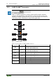
Mapping of process data in the process image of fieldbus systems
The representation of the I/O modules’ process data in the process image depends
on the fieldbus coupler/controller used. Please take this information as well as the
particular design of the respective control/status bytes from the section “Fieldbus
Specific Design of the Process Data” included in the description concerning the
process image of the fieldbus coupler/controller used.
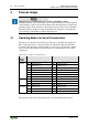
4.1 Operating Modes for Serial Transmission
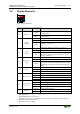
The data to be sent and received will be stored in up to 46 input and output bytes
(D0 ... D45). Data flow is controlled with control and status bytes C0 and S0 or
C1 and S1. The input bytes form the memory area for up to 46 characters, which
were received by the interface. The characters to be transmitted are sent via the
output bytes.
Table 14: Process data for serial transmission
Process
image
length
Input data
Output data
8 bytes
S0
Status byte 0
C0
Control byte 0
S1
Status byte 1
C1
Control byte 1
D0
Data byte 0
D0
Data byte 0
D1
Data byte 1
D1
Data byte 1
D2
Data byte 2
D2
Data byte 2
…
…
D5
Data byte 5
D5
Data byte 5
24 bytes
D6
Data byte 6
D6
Data byte 6
…
…
D21
Data byte 21
D21
Data byte 21
48 bytes
D22
Data byte 22
D22
Data byte 22
…
…
D45
Data byte 45
D45
Data byte 45
The structure of the control and status bytes is described in the tables below.