
Technical data


32 Process Image WAGO-I/O-SYSTEM 750
750-652 Serial Interface RS-232 / RS-485
Manual
Version 1.3.0
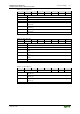
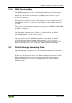
Table 18: Status Byte S1
Bit 7
Bit 6
Bit 5
Bit 4
Bit 3
Bit 2
Bit 1
Bit 0
EOV
EFR
EPR
CTS
BUF_E
IL5
IL4
IL3
IL3
Input length (number of characters received that are available in the input data,
bit 3)
IL4
Input length (number of characters received that are available in the input data,
bit 4)
IL5
Input length (number of characters received that are available in the input data,
bit 5)
BUF_E
Buffer empty (message: transmit inactive)
CTS
This value is always 0
1)
.
EPR
Error parity (message: error during the parity check)
EFR
Error framing (message: data frame is defective)
EOV
Error overrun (message: a character was lost during receipt)
1)
Only applies to flow control "RTS with lead/follow-on time":
Status of the CTS input:
Bit 4 is 0: CTS active
Bit 4 is 1: CTS inactive
For evaluation of the bits of the status byte that signal errors, see chapter
"Diagnostics".
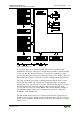
4.2 Data Exchange Mode
The data to be sent and received will be stored in up to 47 input and output bytes
(D0 ... D46). Data flow is controlled with control and status bytes C0 and S0.
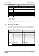
Table 19: Process Data in Data Exchange Mode
Process
image
length
Input data
Output data
8 bytes
S0
Status byte 0
C0
Control byte 0
D0
Data byte 0
D0
Data byte 0
D1
Data byte 1
D1
Data byte 1
D2
Data byte 2
D2
Data byte 2
…
…
D6
Data byte 6
D6
Data byte 6
24 bytes
D7
Data byte 7
D7
Data byte 7
…
…
D22
Data byte 22
D22
Data byte 22
48 bytes
D23
Data byte 23
D23
Data byte 23
…
…
D46
Data byte 46
D46
Data byte 46
The structure of the control and status bytes is described in the tables below.