
Technical data


WAGO-I/O-SYSTEM 750 Commissioning 57
750-652 Serial Interface RS-232 / RS-485
Manual
Version 1.3.0
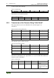
8.3.4 Receiving the Character String "WAGO"
As soon as RA ≠ RR, characters are available in the input byte.
Table 32: Output Process Image
Control byte 0
Control byte 1
Output byte 0
Output byte 1
'0XXX XX0X
'0XXX.XXXX'
XX
XX
Table 33: Receive Data
Status byte 0
Status byte 1
Input byte 0
Input byte 1
0-xxx X (00x)
'0XXX. 1XXX'
XX
XX
There are no receive data
available.
'0XX1. 001X'
'0XXX. 1XXX'
"W"
"A"
The data is available in the
input bytes.
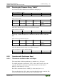
After the 2 characters have been processed, RA is inverted.
Table 34: Receive 2 Characters
Control byte 0
Control byte 1
Output byte 0
Output byte 1
'0XXX XX1X
'0XXX.XXXX'
XX
XX
The receipt of additional characters is indicated by different values for RA and
RR.
Table 35: Receipt of Additional Characters
Status byte 0
Status byte 1
Input byte 0
Input byte 1
'0XXX. X01X'
'0XXX. 1XXX'
XX
XX
There are no receive data
available.
'0XX1. 000X'
'0XXX. 1XXX'
"G"
"O"
The data is available in the
input bytes.
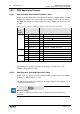
After the characters have been processed, RA is inverted.
Table 36: Output Process Image After Data Transfer
Control byte 0
Control byte 1
Output byte 0
Output byte 1
'0XXX XX0X
'0XXX.XXXX'
XX
XX
8.3.5 Operation with Continuous Send
8.3.5.1 Transmission of a Block of One to 512 Bytes
The output buffer is filled up with data up to number n (n ≤ 512 bytes)
To transmit the buffer content, the bit 3 (SC) of the control byte 0 is set by the
controller. The I/O module begins with the data transmission and the bit 3
(BUF_E) of the status byte 1 is reset.
If all data is transmitted, the bit 3 (BUF_E) of the status byte 1 is set.
The controller takes bit 3 (SC) of the control byte 0 back from the controller. The
end of the transmission from the I/O module is detected this way.