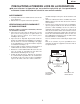
DT-100 SERVICE MANUAL S95N7DT-100// MULTIMEDIA PROJECTOR MODEL DT-100 In the interests of user-safety (Required by safety regulations in some countries) the set should be restored to its original condition and only parts identical to those specified should be used. SHARP CORPORATION This document has been published to be used for after sales service only. The contents are subject to change without notice.
DT-100 CONTENTS Page Page • SPECIFICATIONS ............................................ 3 • IMPORTANT SERVICE SAFETY NOTES (for USA) .............................................. 4 • NOTE TO SERVICE PERSONNEL .................. 6 • OPERATION MANUAL ................................... 10 • DIMENSIONS ................................................. 16 • RESETTING THE TOTAL LAMP TIMER ......... 17 • REMOVING OF MAJOR PARTS ..................... 19 • THE OPTICAL UNIT OUTLINE ......................
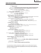
DT-100 SPECIFICATIONS Product type Projector Model DT-100 Video system NTSC3.58/NTSC4.43/PAL/PAL-M/PAL-N/PAL-60/SECAM/DTV480I/DTV480P/ DTV540P/DTV576I/DTV576P/DTV720P/DTV1035I/DTV1080I/DTV1080I-50 Display method Single Chip Digital Micromirror DeviceTM (DMDTM) by Texas Instruments DMD panel Panel size: 0.53 ", 1chip DMD No. of dots: 409,920 dots (854 [H] × 480 [V]) Lens 1–1.15 × zoom lens, F2.4–2.6, f = 19.0–21.
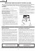
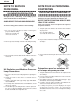
DT-100 IMPORTANT SERVICE SAFETY NOTES (for USA) Ë Service work should be performed only by qualified service technicians who are thoroughly familiar with all safety checks and servicing guidelines as follows: » Use an AC voltmeter with sensitivity of 5000 ohm per volt., or higher, sensitivity to measure the AC voltage drop across the resistor (See Diagram). » All checks must be repeated with the AC plug connection reversed.
DT-100 PRECAUTIONS A PRENDRE LORS DE LA REPARATION Ë Ne peut effectuer la réparation qu' un technicien spécialisé qui s'est parfaitement accoutumé à toute vérification de sécurité et aux conseils suivants. AVERTISSEMENT conduite électrique ou une prise de terre branchée à la terre. • Utiliser un voltmètre CA d'une sensibilité d'au moins 5000Ω/V pour mesurer la chute de tension en travers de la résistance.
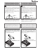
DT-100 NOTE TO SERVICE NOTE POUR LE PERSONNEL PERSONNEL D’ENTRETIEN 123456789012345678901234567890121234567890123456 123456789012345678901234567890121234567890123456 123456789012345678901234567890121234567890123456 123456789012345678901234567890121234567890123456 UV-RADIATION PRECAUTION 123456789012345678901234567890121234567890123456 123456789012345678901234567890121234567890123456 PRECAUTION POUR LES RADIATIONS UV 123456789012345678901234567890121234567890123456 123456789012345678901234567890121234567
DT-100 123456789012345678901234567890121234567890123456 123456789012345678901234567890121234567890123456 123456789012345678901234567890121234567890123456 123456789012345678901234567890121234567890123456 123456789012345678901234567890121234567890123456 123456789012345678901234567890121234567890123456 UV-RADIATION PRECAUTION (Continued) 123456789012345678901234567890121234567890123456 123456789012345678901234567890121234567890123456 123456789012345678901234567890121234567890123456 PRECAUTION POUR LES RADIA
DT-100 WARNING: High brightness light source, do not stare into the beam of light, or view directly. Be especially careful that children do not stare directly in to the beam of light. WARNING: TO REDUCE THE RISK OF FIRE OR ELECTRIC SHOCK, DO NOT EXPOSE THIS UNIT TO MOISTURE OR WET LOCATIONS. CAUTION The lighting flash with arrowhead within a triangle is intended to tell the user that parts inside the product are risk of electric shock to persons. RISK OF ELECTRIC SHOCK.
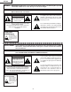
DT-100 Precautions for using lead-free solder 1 Employing lead-free solder "PWBs" of this model employs lead-free solder. The LF symbol indicates lead-free solder, and is attached on the PWBs and service manuals. The alphabetical character following LF shows the type of lead-free solder. Example: LFa Indicates lead-free solder of tin, silver and copper. 2 Using lead-free wire solder When fixing the PWB soldered with the lead-free solder, apply lead-free wire solder.
DT-100 Operation Manual 10
DT-100 11
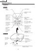
DT-100 ON button For turning the power on. STANDBY button For putting the projector into the standby mode. MENU/HELP button For displaying adjustment and setting screens, and help screen. KEYSTONE button For entering the Keystone Correction mode. RETURN button For returning to the previous menu screen during menu operations. Adjustment buttons ( / / / ) For selecting menu items. For adjusting the Keystone Correction when in the Keystone Correction mode.
DT-100 13
DT-100 14
DT-100 Connection Pin Assignments 15
DT-100 DIMENSIONS Units: inches(mm) 16
DT-100 RESETTING THE TOTAL LAMP TIMER ● Resetting the total lamp timer When replacing the lamp, reset the total lamp timer in the procedure below. Lamp ■ It is recommended that the lamp (sold separately) be replaced when the remaining lamp life becomes 5% or less, or when you notice a significant deterioration in the picture and color quality. The lamp life (percentage) can be checked with the on-screen display.
DT-100 ■Keystone correction range expansion and vertical compression adjustment function The variable range of the keystone can be expanded to over the user adjustable range by using the following RS-232C commands. In addition, the vertical compression can be adjusted.
DT-100 REMOVING OF MAJOR PARTS 1. Removing the lamp door and the lamp unit 1-1. Loosen the lamp door fixing screw. Lift off the lamp door. 1-2. Remove 2 lamp unit fixing screws to detach the lamp unit. 1-1 Lamp Door 1-2 1-2 Lamp Unit 2. Removing the top body 2-1. Remove 8 top body fixing screws to detach the Top body.
DT-100 3. Removing the main PWB unit 3-1. Remove all connectors from the main PWB unit. 3-2. Remove 2 terminal fixing screws. 3-3. Remove 3 main PWB fixing screws to detach the main PWB unit. 3-3 [RC] [CW] [FA] [MO] [LF] [BB] 3-1 MAIN PWB Unit [FD] [FC] [SO] [EA] [FB] 3-3 3-2 4. Removing the speaker, fan, and power supply ballast unit 4-1. Remove the speaker. 4-2. Remove 2 fans for the power supply ballast unit and 1 fan for the optical mechanism unit. 4-3.
DT-100 5. Removing the optical mechanism unit and RC light receiver PWB 5-1. Remove 4 optical mechanism unit fixing screws to detach the optical mechanism unit. 5-2. Remove the RC light receiver PWB unit. 5-1 Optical Mechanism Unit RC Light Receiver PWB 5-2 6. Removing the photosensor PWB unit, blower fan, DMD PWB, and DMD 6-1. Remove 1 photosensor PWB fixing screw to detach the photosensor PWB. 6-2. Remove 2 blower fan fixing screws to detach the blower fan. 6-3.
DT-100 THE OPTICAL UNIT OUTLINE Layout for proper setup of the optical components and parts (top view) (Schematic diagram) Projection lens Illumination lens 2 Illumination lens 1 Reflection mirror Plastic Lens Color wheel UV Glass DMD Item Lamp UV/IR cut filter (UV GLASS) Color wheel Rod (ROD INTEGRATOR) Illumination lens (ILLUMINATION LENS 1, 2) Reflection mirror Condencer Lens (PLASTIC LENS) DMD Projection lens Lamp Rod Integrator Function Light source. DC high-pressure mercury lamp.
DT-100 If shading shown in Figure 1 appears on the screen after replacing DMD, turn the adjustment screw of the optical engine to adjust the lighting area of DMD. 1. Loosen the adjustment lever fixing screw 1. After adjusting the lighting area with the adjustment lever 2, tighten the adjustment lever fixing screw 1. Tightening order: 1→2→3→4 Screw torque: 0.44 ± 0.05 N·m When mounting DMD, tighten the 4 screws evenly. Fig.
DT-100 ELECTRICAL ADJUSTMENT No. Adjusting point Adjusting conditions Adjusting procedure 1 EEPROM initialization 1. Turn on the power (with the lamp on) and warm up the set for 15 minutes. » Make the following settings. Press S2551 to call the process mode and execute "SS2" on SS menu. 2 Model setting (Process menu) 1. Select the following group and subject. Group: CONFIRM Subject: MODEL 1. Set as below. : 1 (default) 3 Adjustment of CW index 1. Signal input: Send 256 STEP color bar.
DT-100 Check items No. Adjusting point Adjusting conditions Adjusting procedure 1 Adjustment of RGB brightness 1. Select the following group and subjects. Group : CONFIRM/AD Subject : R-BRIGHT G-BRIGHT B-BRIGHT (Process GAMMA interlock) 1. Check the fixed value. Fixed value : 127 2 Adjustment of Component offset 1. Feed 10-step signal with 480P component 100% amplitude. 2. Select the following group and subjects. Group : CONFIRM/AD Subject : C-R-OS C-B-OS (Process GAMMA interlock) 1.
DT-100 No. Adjusting point Adjusting conditions Adjusting procedure 6 Adjustment of Video Tint 1. Feed split color bar. 1. Check the fixed value. 2. Select the following group Fixed value : 128 and subject. Group : CONFIRM/VIDEO Subject : V-HUE 7 Adjustment of Video color saturation 1. Select the following group 1. Check the fixed value. and subject. Fixed value : 154 Group : CONFIRM/VIDEO Subject : V-COLOR 8 RGB tone reproduction adjustment 1. Feed the SMPTE pattern signal.
DT-100 No. Adjusting point Adjusting conditions Adjusting procedure 15 RS232C operation check 1. Connect the unit and a PC with the RS232C cable. 1. Send a command from the PC, and check it functions correctly. 16 Model name and version check 1. Select the following group. Group : INFO/VERSION. 1. The model name appears in the MODEL field, and the firmware version in the VERSION field. Check that they are correct. 17 Delivery settings 1. Make the following settings.
DT-100 » Adjustment mode process menu 1st Layer 2nd Layer ADJUST CW/Auto KS Default CW-INDEX 20 1st Layer 2nd Layer INFO VERSION CAL AD/DLP SS CONFIRM AD DLP VIDEO PATTERN Default MODEL − VER.
DT-100 [Adjustment of ballast unit output power (lamp power)] 1. List of parts requiring adjustment When replacing the following parts, adjust the ballast unit output power (lamp power). 1 2 3 4 5 Part name Cement resistor Control PWB Ballast microprocessor 5V regulator PWM controller Ref No. R905 -IC7707 IC7704 IC7701 Part code RR-FZA002WJZZ DUNTKD148WEF0 RH-iXB458WJZZ VHITA78L05F-1Y VHIM51995AF-1Y 2.
DT-100 TROUBLE SHOOTING TABLE Checking the basic operation NO Does the power LED light up or flash in red or green? Has P1701 come off or is it loose? YES Does the set function with its keys or the remote controller? NO NO Go to "Main PWB check". YES Lamp does not turn on or it turns off in a short time. YES Go to "Checking the lamp light-up". NO Nothing is displayed or white vertical line noise YES Go to "DMD system check". NO Colors are not displayed YES normally.
DT-100 Main PWB check Is 6 V applied to TL1702 and 13 V to TL1703? NO ballast PWB check". YES Is approx. 6 V applied to TL1742? TL1741? NO Check IC1742 and peripheral circuits. YES Is 1.5 V applied to Go to "Power supply NO Check IC1741 and peripheral circuits. YES Is 3.3 V applied to pin(1) Is 3.3 V applied to TL1762? YES peripheral circuits. NO Check IC1762 and Is 3.18 V applied to pin(1) peripheral circuits. NO of IC2001? YES Check IC2001 and Check IC1791 and peripheral circuits.
DT-100 DMD system check Check P2501 for breakage and solder crack and peripheral resistance for solder crack. Check SC9101 for breakage and solder crack. Is there any vertical stripe (block noise) on the NO NO YES Is the screen all black? YES Is 3.27 V applied to IC2231 NO pin(1) and 1.8 V to TL2231? YES Is 400 MHz on IC2241 pin (20)? YES NO Is approx. 7 V applied to TL9303? YES NO Is approx. 26 V applied to TL9301? YES NO Is approx.
DT-100 Power supply PWB check Is 6 V applied to pins (7) and (8) of the connector P704? NO 1 NO Check peripheral circuits of IC703. YES Is 13 V applied to pins (3) and (4) of the connector P704? YES Does the lamp turn on? NO YES Check the main PWB. Are connectors P704 and CN901 fully inserted? NO Securely insert the connectors. NO Is pin (11) of the connector P704 at "H"? YES Is DC voltage of 380 V applied to both ends of C704? NO Check the main PWB.
DT-100 1 Are connectorsP701 and P702 fully inserted? NO Securely insert the connectors. YES Is AC voltage between 100 − 240 V applied to both ends of C707? NO Replace F701. YES NO Is the bimetal broken? (Connection between 1 and 2 of P702) Press the red button on the bimetal. YES NO Is R717 open? YES Check that P704 connector pin (11) is at "H". Replace R717. NO Is R705 open? YES Replace F705. Check that the power supply FAN FB and FC are not stopped. 34 Check peripheral circuits of IC703.
DT-100 Checking the lamp light-up Does the lamp turn on when the power is turned YES Go to "Check when the lamp turns off soon after turning on". YES Securely insert the connectors. YES Securely insert the connectors. NO Is the lamp tight in the socket? NO Has the FPC cable to SC3581 come off or is it loose? NO Is rotating sound of the color wheel heard? NO Check IC3581 and peripheral circuits. (Refer to the waveform chart 2.) YES Is approx. 0.
DT-100 Check when the lamp turns off soon after turning on Have connectors P1703, P1721, P1722, P1723 and P1724 come off or are they loose? YES Securely insert the connectors. NO Is each cooling fan rotating? NO Check the cooling fan. YES Is approx. 3 V applied to TL1721? NO Check peripheral circuits of Q1721. NO Check IC1761, IC3581 and peripheral circuits. YES Is 12 V applied to TL1761? Go to "DMD system check". YES Is 2.5 V applied to TL1763? NO YES Is 3.
DT-100 RGB and component signal check Send component signal or RGB signal of 1080i (or 720P) from INPUT 1 or INPUT 2. Select INPUT 1 or INPUT 2 using keys on the main unit or the remote control. YES Is image displayed normally? YES End NO Are picture signals sent to TL3201, TL3204, and TL3205? NO Check IC3002 and the peripheral circuits (check IC3052 for INPUT 2). YES Is 3.3V applied to TL1792? NO Check IC1792 and peripheral circuits. NO Check IC1763 and peripheral circuits. YES Is 3.
DT-100 S-VIDEO (INPUT 3) check VIDEO (INPUT 4) check Send S-Video signal (color signal) from INPUT 3. Select INPUT 3 using keys on the main unit or the remote control. Is image displayed normally? Send VIDEO signal from INPUT 4. Use buttons on the main unit or the remote control to select INPUT 4. YES End NO Is image displayed in black and white? YES Check S-VIDEO terminal and peripheral circuits of Q3311. NO Check S-VIDEO terminal and peripheral circuits of Q3301.
DT-100 -MEMO- 39
DT-100 BLOCK DIAGRAM H G F E D C B A 1 2 3 4 5 6 40 7 8 9 10
DT-100 10 11 12 13 14 15 41 16 17 18 19
DT-100 OVERALL WIRING DIAGRAM H G F DU E P3502 RH-HXA015WJPZ B+3.
DT-100 DUNTKD139FMF7 PHOTO 10 11 12 13 14 15 43 16 17 18 19
DT-100 DESCRIPTION OF SCHEMATIC DIAGRAM VOLTAGE MEASUREMENT CONDITION: 1. Voltages at test points are measured at the supply voltage of AC 220V. Signals are fed by a color bar signal generator for servicing purpose and the above voltages are measured with a 20k ohm/V tester. WAVEFORM MEASUREMENT CONDITION: 1. Waveforms at test points are observed at the supply voltage of AC 220V. Signals are fed by a color bar signal generator for servicing purpose. INDICATION OF RESISTOR & CAPACITOR: RESISTOR 1.
DT-100 WAVEFORMS 10 11 12 13 14 15 45 16 17 18 19
DT-100 SCHEMATIC DIAGRAM H Ë MAIN UNIT-1/8 G F iXB589WJ E D iXB589WJ C B A 1 2 3 4 5 6 46 7 8 9 10
DT-100 10 11 12 13 14 15 47 16 17 18 19
DT-100 Ë MAIN UNIT-2/8 H G F E D C B A 1 2 3 4 5 6 48 7 8 9 10
DT-100 10 11 12 13 14 15 49 16 17 18 19
DT-100 Ë MAIN UNIT-3/8 H G F E D C B A 1 2 3 4 5 6 50 7 8 9 10
DT-100 10 11 12 13 14 15 51 16 17 18 19
DT-100 Ë MAIN UNIT-4/8 H G F E D C B A 1 2 3 4 5 6 52 7 8 9 10
DT-100 10 11 12 13 14 15 53 16 17 18 19
DT-100 Ë MAIN UNIT-5/8 H G F E D C B A 1 2 3 4 5 6 54 7 8 9 10
DT-100 10 11 12 13 14 15 55 16 17 18 19
DT-100 Ë MAIN UNIT-6/8 H G F E D C B A 1 2 3 4 5 6 56 7 8 9 10
DT-100 10 11 12 13 14 15 57 16 17 18 19
DT-100 Ë MAIN UNIT-7/8 H G F E D C B A 1 2 3 4 5 6 58 7 8 9 10
DT-100 10 11 12 13 14 15 59 16 17 18 19
DT-100 Ë MAIN UNIT-8/8 H G F E D C B A 1 2 3 4 5 6 60 7 8 9 10
DT-100 10 11 12 13 14 15 61 16 17 18 19
DT-100 Ë DMD UNIT-1/3 H G F E D C B A 1 2 3 4 5 6 62 7 8 9 10
DT-100 10 11 12 13 14 15 63 16 17 18 19
DT-100 Ë DMD UNIT-2/3 H G F E D C B A 1 2 3 4 5 6 64 7 8 9 10
DT-100 10 11 12 13 14 15 65 16 17 18 19
DT-100 Ë DMD UNIT-3/3 H G F E D C B A 1 2 3 4 5 6 66 7 8 9 10
DT-100 10 11 12 13 14 15 67 16 17 18 19
DT-100 Ë BALLAST POWER UNIT H G F E D C B A 1 2 3 4 5 6 68 7 8 9 10
DT-100 10 11 12 13 14 15 69 16 17 18 19
DT-100 Ë BALLAST CONTROL UNIT H G F E D C B A 1 2 3 4 5 6 70 7 8 9 10
DT-100 458 10 11 12 13 14 15 71 16 17 18 19
DT-100 Ë PHOTOSENSOR UNIT H G F E D C B A 1 2 3 4 72 5 6
DT-100 Ë R/C UNIT H G F E D C B A 1 2 3 4 73 5 6
DT-100 PRINTED WIRING BOARD ASSEMBLIES H G F E D C B A MAIN Unit (Side-A) 1 2 3 4 5 6 74 7 8 9 10
DT-100 10 11 12 13 14 15 75 16 17 18 19
DT-100 H FB1711 FB1710 P1703 R1706 C1726 R1704 SC2531 G P2533 R2528 R2529 R2522 C2002 R2503 R2524 F R2241 R2244 C2223 R2213 C2222 R2212 C2028 C2031 FB2201 R2001 C2003 C2001 R2525 R2521 C2245 R2516 C2248 R2514 C2251 R2512 R2518 R2505 R2510 R2508 R2504 R2506 C2241 P1704 IC2001 FB1709 IC2241 R2517 FB2241 R2515 C2250 R2513 C2253 C2252 C2246 C2242 R2511 R2509 R2019 R2507 FB1708 C2221 R2523 R2527 R2204 R2211 C2220 C2205 C2206 IC2002 R2209 IC2201 R2210 C2219
DT-100 P1703 P1721 P3562 P1702 SC3581 FB3566 L1723 C1724 FB1729 FB1728 FB1727 D1725 R3592 R3593 Q1724 P1723 R3589 C3588 D1733 R3588 C3586 L1727 R1727 R3591 R1707 C3591 FB3565 C3572 FB3585 C1705 FB3584 R1708 FB1707 R1705 FB3583 FB3582 FB1721 FB1723 FB1722 R1706 C1726 R1704 D1730 FB1711 FB1710 P1705 P2533 R2528 D2573 D2572 P1724 C1725 Q1725 D1726 FB1732 FB1731 D1731 R1728 R2529 FB1730 D2571 22 21 20 S2552 19 P3561 18 17 S2555 16 15 R1702 Q1701 D1701 14
DT-100 H G F E D C B A MAIN Unit (Side-B) 1 2 3 4 5 6 78 7 8 9 10
DT-100 10 11 12 13 14 15 79 16 17 18 19
DT-100 H R3578 C3571 TH3561 R3577 D1702 C1722 C1704 D3581 D3582 D1723 D3584 D3583 C3595 R1721 Q1722 C3584 C3585 R3597 R3590 C3589 R1724 C3593 D1721 R1726 R1722 R1723 C3583 C1771 R1773 R1780 R1781 C1777 R3596 G C1763 C1761 R1764 R1729 C3592 Q1721 D1722 C1728 L1721 C3594 R1725 R3595 IC3581 IC1762 R1765 L1728 C2231 R1772 C1775 C1776 R1775 R1732 C1778 R2577 R2579 R2582 R2584 R2576 R2578 R2580 R2581 R2583 C1729 C1769 IC1721 L1761 C1756 R1747 C3561 IC1742
DT-100 P2501 R1729 Q1722 C2231 C2254 R2233 R2013 D1763 D2231 C2232 C2233 R2232 FB2251 C2004 R2017 C1768 X2251 R2520 L2005 R2519 R2501 R3582 C2033 R2010 R2007 IC1721 L2004 R3587 C1729 C2035 R2009 R2014 R2012 R2248 R2247 R2008 R2015 R2531 R2242 C2247 R2243 R2245 R2246 R2502 IC2251 C2255 R2252 R2234 R2235 R2231 C2256 IC2231 C2032 C2030 R2016 C2029 C2034 C2501 R2263 C2027 C2014 C2019 C2022 IC2262 R2201 R1743 C2201 C2202 C2011 R2526 R2018 D1741 C2012 C200
DT-100 H G F DMD Unit (Side-A) E TH9102 R9102 C9513 C9512 C9318 C9314 C9315 R9303 FB9302 R9305 C9503 C9311 IC9301 C9317 C9502 C9508 R9304 C9309 R9302 R9301 C9504 C9509 C9506 FB9303 D9303 D9302 L9301 C9301 C9303 L9302 D9301 C9302 C9308 C9514 C9304 C9305 FB9301 C9501 C9306 82 6 5 4 SC9101 C9510 C9312 C9316 DMD Unit (Chip Parts Side-A) A C9307 3 2 1 C9505 C C9507 C9313 C9102 C9101 R9103 D C9310 C9511 B
DT-100 H G F DMD Unit (Side-B) E D C B A 1 2 3 4 83 5 6
DT-100 H G F E D C B A BALLAST POWER Unit (Side-A) 1 2 3 4 5 6 84 7 8 9 10
DT-100 10 11 12 13 14 15 85 16 17 18 19
DT-100 H G F E D C B A BALLAST POWER Unit (Side-B) 1 2 3 4 5 6 86 7 8 9 10
DT-100 10 11 12 13 14 15 87 16 17 18 19
DT-100 H R762 R708 G C705 R703 R704 R711 C703 C706 R710 R707 C713 R706 R705 C702 D705 R702 IC902 R718 R732 C708 R728 R712 D704 D722 R715 F FB706 FB705 R721 R725 E R730 D706 R731 D707 D719 R763 D720 R764 C903 D C716 R917 C717 D702 C C923 C92 B A BALLAST POWER Unit (Chip Parts Side-B) 1 2 3 4 5 6 88 7 8 9 10
DT-100 FB704 FB701 R708 FB702 R707 FB704 R706 R760 R759 D713 C719 R758 R757 R736 C718 C724 C729 C723 R749 R735 R754 R752 R756 R743 R753 C736 R755 R751 D710 IC704 R738 C722 Q705 R737 D708 R750 C701 R733 R742 Q706 C739 R740 R748 C921 R918 C924 D915 R933 R904 R912 R911 R914 D906 R903 R908 R913 R907 R909 FB904 R921 R923 R924 R920 R931 R930 FB903 R941 R947 R938 Q907 R926 C925 R932 C919 R927 C918 R902 R901 R917 R928 R934 Q904 R942 R940 C905 C904
DT-100 H G F BALLAST CONTROL Unit (Side-A) E R7704 C7701 R7708 P7701 IC7709 D7703 R7720 R7723 Q7707 R7726 R7717 C7713 R7721 C7719 R7731 C7717 C7744 C7710 C7731 D7712 C7752 R7772 D7711 C7715 R7762 C7734 C R7719 C7712 R7775 R7776 C7709 R7755 C7742 C7728 R7793 R7770 R7769 C7727 D7713 R7725 R7724 C7746 C7739 IC7707 C7741 C7737 X7701 R7761 R7712 C7707 C7745 D7714 C7718 R7787 D IC7701 C7733 C7736 D7715 B BALLAST CONTROL Unit (Chip Parts Side-A) A 1 2 3 4 90 5 6
DT-100 H G F BALLAST CONTROL Unit (Side-B) E C7751 C7749 C7723 R7783 R7740 R7747 R7773 R7777 R7760 R7751 R7757 R7774 R7778 C7743 Q7709 R7784 IC7705 R7779 R7741 C7725 R7742 C7726 R7738 R7789 R7790 R7791 R7792 R7736 R7722 C7750 R7780 Q7708 R7767 R7737 Q7706 C7740 R7729 Q7705 R7734 C Q7703 R7781 R7744 R7745 R7716 C7738 R7732 R7727 C7716 R7766 R7733 Q7704 R7748 R7756 R7786 R7785 R7701 R7730 C7724 R7759 C7730 R7764 R7771 R7763 R7765 R7788 Q7711 R7735 R7752 D770
DT-100 H G PHOTOSENSOR Unit (Side-A) F E D PHOTOSENSOR Unit (Side-B) C1101 R1101 R1104 R1111 R1108 R1107 R1103 R1109 R1102 IC1101 C1102 B R1110 P1101 C R1106 PHOTOSENSOR Unit (Chip Parts Side-B) A 1 2 3 4 92 5 6
DT-100 H G R/C Unit (Side-A) F E D C R/C Unit (Side-B) B A 1 2 3 4 93 5 6
DT-100 Ref. No. Part No. ★ Description PARTS LIST Code Ref. No. INTEGRATED CIRCUITS HOW TO ORDER REPLACEMENT PARTS To have your order filled promptly and correctly, please furnish the following informations. in USA: 2. REF. NO. 4. DESCRIPTION 5. CODE 6. QUANTITY Contact your nearest SHARP Parts Distributor. For location of SHARP Parts Distributor, Please call Toll-Free; 1-800-BE-SHARP in CANADA: Contact SHARP Electronics of Canada Limited Phone (416) 890-2100.
DT-100 Ref. No. ★ Part No. Description Code Ref. No. DUNTKD139FMF7 J J J J J J J J J J J J J J J J J J J J J J J J J J J J J J J J J J J J J J J J J J J J J J J J J J J J J J J J J J J J J J J J J J J J J J DAN202K DAN202K RB551V30 RB551V30 RB551V30 RB551V30 RB551V30 RB551V30 RB551V30 RB551V30 Zener Diode, 2V SFPA73 HSU119 Zener Diode, 3.
DT-100 Ref. No. Part No. ★ Description Code Ref. No.
DT-100 Ref. No. Part No. ★ Description Code Ref. No.
DT-100 Ref. No. Part No. ★ Description Code Ref. No.
DT-100 Ref. No. Part No. ★ Description Code Ref. No.
DT-100 Ref. No. Part No.
DT-100 Ref. No. ★ Part No. Description Code Ref. No. Description DUNTKD140WEF0 DUNTKD141WEF0 DMD UNIT PHOTOSENSOR Unit INTEGRATED CIRCUIT IC9301 RH-iXA384WJN1Q BR IC1101 VHiLM393A//-1Y IC1102 VHPGP2S40//-1S J SFPA73 J SFPA73 J Zener Diode, 8.2V AE COILS J Coil J Coil AD AD C1101 C1102 VCKYCY1EF104ZY J 0.1 VCKYCY1EF104ZY J 0.
DT-100 Ref. No. ★ Part No. Description Code Ref. No.
DT-100 Ref. No. Part No. ★ Description Code Ref. No. ★ Part No.
DT-100 Ref. No. ★ Part No.
DT-100 Ref. No. Part No.
DT-100 CABINET AND MECHANICAL PARTS 47 48 17 14 H 29 1-3 1 17 24 1-4 1-2 23 A G 35 8 8-2 W M 1-1 17 V 8-1 F B 33 11-2 17 45 11-3 17 25 E 43 K M 11 G C L 30 N P 26 11-1 X X D Q 46 R S T U 31 H 15 D 43 13 31 21 39 31 K L 42 21 43 W R C 43 S 2-2-3 T N 43 A 2-2 D Q 2 P 41 20 F B 34 J C J H G B 36 V 2-2-1 4 2-6 43 2-1 40 5 2-3 2-1-4 U 2-1-3 9 A 2-5 2-1-1 2-4 2-1-2 1 2 3 4 106 5 6
DT-100 Ref. No. Part No.
DT-100 OPTICS MECHANISM PARTS H G 4-29 18 40 19 22 40 27 16 32 F 6 4-32 4-29 4-12 28 4-29 4-7 4-26 37 38 4-16 4-29 4-29 4-29 7 4-13 4-11 4-25 E 4-29 4-14 4-29 4-5 4-36 4-28 4-4 4-22 4-31 4-35 4-17 4-30 40 4-34 4-18 4-2 4-33 4-36 4-23 4-8 D 4-19 4-6 4-3 4-29 4-24 4-20 4-1 4-21 4-27 4 4-15 4-31 4-10 C 4-31 3 4-9 B A 1 2 3 4 108 5 6
DT-100 Ref. No. Part No. ★ Description Code Ref. No. RRMCGA430WJSA QACCDA007WJPZ QCNWGA075WJPZ TiNS-B999WJZZ SSAKA0160CEZZ J J J J J Remote Control unit AC Cord for USA RGB-RCA Cable Operation Manual Polyethyrene Bag ★ Description Code PACKING PARTS (NOT REPLACEMENT ITEM) SUPPLIED ACCESSORIES X1 å X2 X3 X4 X5 Part No.
DT-100 PACKING OF THE SET X2 X3 X4 S2 SET X1 S3 Lens cap S4 FRONT SIDE S1 110
DT-100 111
DT-100 COPYRIGHT © 2005 BY SHARP CORPORATION ALL RIGHTS RESERVED. No part of this publication may be reproduced, stored in a retrieval system, or transmitted in any form or by any means, electronic, mechanical, photocopying, recording, or otherwise, without prior written permission of the publisher. TQ1933-S Sep. 2005 Printed in Japan Design and Production Information Design : JAPAN Production : NSEC MY.