XV-Z90U DT-200 SERVICE MANUAL S02S1XV-Z90U/ THEATOR PROJECTOR MODELS XV-Z90U DT-200 In the interests of user-safety (Required by safety regulations in some countries) the set should be restored to its original condition and only parts identical to those specified should be used. CONTENTS Page » SPECIFICATIONS ......................................................................................................................................2 » IMPORTANT SERVICE SAFETY NOTES (for USA) ................
XV-Z90U DT-200 Specifications Product type Model Video system Display method DLP panel Lens Projection lamp Video input signal S-video input signal Component input signal (INPUT 1) Component input signal (INPUT 2) Component RGB input signal (INPUT 2) Horizontal resolution RGB input signal Pixel clock Vertical frequency Horizontal frequency Computer control signal Rated voltage Input current Rated frequency Power consumption Heat dissipation Operating temperature Storage temperature Cabinet I/R carrie
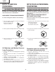
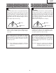
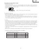
XV-Z90U DT-200 IMPORTANT SERVICE SAFETY NOTES (for USA) Ë Service work should be performed only by qualified service technicians who are thoroughly familiar with all safety checks and servicing guidelines as follows: » Use an AC voltmeter with sensitivity of 5000 ohm per volt., or higher, sensitivity to measure the AC voltage drop across the resistor (See Diagram). » All checks must be repeated with the AC plug connection reversed.
XV-Z90U DT-200 NOTE TO SERVICE PERSONNEL 12345678901234567890123456789012123456789012345 12345678901234567890123456789012123456789012345 NOTE POUR LE PERSONNEL D’ENTRETIEN 12345678901234567890123456789012123456789012345 UV-RADIATION PRECAUTION 12345678901234567890123456789012123456789012345 12345678901234567890123456789012123456789012345 PRECAUTION POUR LES RADIATIONS UV 12345678901234567890123456789012123456789012345 12345678901234567890123456789012123456789012345 The light source, metal halide lamp,
XV-Z90U DT-200 12345678901234567890123456789012123456789012345 12345678901234567890123456789012123456789012345 12345678901234567890123456789012123456789012345 12345678901234567890123456789012123456789012345 1234567890123456789012345678901212345678901234 UV-RADIATION PRECAUTION (Continued) 1234567890123456789012345678901212345678901234 1234567890123456789012345678901212345678901234 PRECAUTION POUR LES RADIATIONS UV (Suite) 12345678901234567890123456789012123456789012345 1234567890123456789012345678901212
XV-Z90U DT-200 WARNING: High brightness light source, do not stare into the beam of light, or view directly. Be especially careful that children do not stare directly in to the beam of light. WARNING: TO REDUCE THE RISK OF FIRE OR ELECTRIC SHOCK, DO NOT EXPOSE THIS UNIT TO MOISTURE OR WET LOCATIONS. CAUTION The lighting flash with arrowhead within a triangle is intended to tell the user that parts inside the product are risk of electric shock to persons. RISK OF ELECTRIC SHOCK.
XV-Z90U DT-200 Precautions for using lead-free solder 1 Employing lead-free solder "Front-R/C, LED, DVi-TANi, terminal 2,Rear-R/C and key PWBs" of this model employs lead-free solder. The LF symbol indicates lead-free solder, and is attached on the PWBs and service manuals. The alphabetical character following LF shows the type of lead-free solder. Example: LFa Indicates lead-free solder of tin, silver and copper.
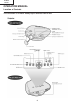
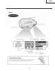
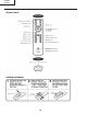
XV-Z90U DT-200 OPERATION MANUAL Location of Controls This illustration is XV-Z90U. A body logo is different from DT-200.
XV-Z90U DT-200 9
XV-Z90U DT-200 LIGHT button (XV-Z90U) FREEZE button (DT-200) 10
XV-Z90U DT-200 Connection Pin Assignments 11
XV-Z90U DT-200 Dimensions This illustration is XV-Z90U. A body logo is different from DT-200.
XV-Z90U DT-200 REMOVING OF MAJOR PARTS 1. Removing the swivel stand and the lamp box. 1-1. Remove lock lever, and remove the swivel stand. 1-2. Loosen 1 scrwew, and remove the lamp door . 1-3. Loosen 3 screws, and take out a lamp box. Lamp Box 1-3 Lamp Door 1-2 Swivwl Stand Lock Lever 1-1 Swivwl Stand 2. Removing the side covers and the top body. Side Cover 2-2 2-1. Push front end of the side cover from bottom, and remove a hook. 2-2.
XV-Z90U DT-200 3. Removing the main PWB. 3-1. Remove 6 screws. 3-2. Remove each connector on the main PWB. 3-1 3-2 [DA] [TD] [TF] [BA] 3-2 [RB] Main PWB [FD] [FB] [PG] [TH] [TC] [ED] [FC] [FA] 3-2 3-2 4. Removing the Ballast unit. Lens Shift Knob 4-1. Remove lens shift knob. 4-2. Remove 2 screws, and remove the ballast socket. 4-3. Remove 3 screws, and remove the ballast unit. 4-4. Remove shielding plate, and remove 2 connectors on the ballast PWB. 4-5. Remove 2 screws, and remove ballast PWB.
XV-Z90U DT-200 6. Removing the power unit. 6-1. Remove each connector on the power PWB. 6-2. Remove 2 screws, and remove the power unit fan. 6-3. Remove 3 screws, and take out the power unit assembly. 6-4. Remove 5 screws, and remove power shield. 6-2 6-3 Power Unit Fan 6-4 Power Shield 6-1 [EB] [EA] [EC] Power PWB 6-4 7. Removing the each other PWBs. AC Socket 7-1. Remove 1 screw, and remove front R/C receiver PWB unit . 7-2. Remove 1 screw, and remove LED PWB unit. 7-3.
XV-Z90U DT-200 Precautions in replacing the DMD chip Note: Be careful not to allow dust and fingerprint on the cover glass of DMD chip and prism surface of optical engine. 1. When you fix 4screws of backer plate assembly, press backer plate to formatter PWB and fix by cross multiply step by step. 2. If something shade appears on the projection screen like Fig1, release 2 screws on mirror adjusting plate and move that plate to adjust illumination area of DMD chip.
XV-Z90U DT-200 Outline of the optical unit Relay lenses Rod lens Reflector Projection lens Lamp UV/IR filter Prism DMD chip Zoom ring Width Item Lamp UV/IR filter Color wheel Rod lens Relay lenses Reflector Prism DMD chip Projection lens Color wheel Focus ring Function Light source. DC-driven high-pressure mercury vapor lamp. Used to absorb ultraviolet and infrared rays. Used to let the source light through the color filter and to separate it into R, G and B colors.
XV-Z90U DT-200 RESETTING THE TOTAL LAMP TIMER You need to reset the lamp timer every time you replace the lamp and confirm it is reset on the “Lamp Timer” menu. How to reset the total lamp timer. 1. Plug the power cord 2. Press POWER ON on the projector to reset the lamp timer. “LAMP 0000H” is displayed on the screen. Maintenance Indicators TEMP.
XV-Z90U DT-200 ELECTRICAL ADJUSTMENT No. Adjustment Items Adjustment Conditions Adjustment Procedures 1 Initialization of EEPROM 1. Turn on the power (the lamp lights up) and warm up the system for 15 minutes. 1. Carry out the following setting. Using the remote controller or press S2002 to enter the process mode, and execute SS2 on SS menu. 2 Adjustment of CW index 1. Input the gradation pattern of RGB. 2. Select the following group and subject. Group: DLP Subject: Select CW-INDEX. 1.
XV-Z90U DT-200 No. Adjustment Items Adjustment Conditions Adjustment Procedures 4 Adjustment of DTV brightness/ contrast 1. Feed 480P 100% Black/White window pattern signal. 2. Select the following group and subject. Group: DTV Subject: Bright Contrast (Process gamma interlock) 1. On the bit-less screen, adjust in the order of black side Bbright and white side Contrast. Adjust the black level so that bright green bit-less may disappear and may turn pale green.
XV-Z90U DT-200 No. Adjustment Items Adjustment Conditions Adjustment Procedures 12 Adjustment of Video color saturation 1. Select the following group and subject. Group: VIDEO Subject: N-Color P-Color S-Color 1. Confirm the fixed value. N-Color: 10 P-Color: 10 S-Color: 10 13 Adjustment of DTV white balance 1. Feed 480I75% gray signal. 2. Select the following group and subject. Group: DLP Subjects: R-Contrast(R) B-Contrast(B) 1. Confirm the fixed value.
XV-Z90U DT-200 No. Adjustment Items Adjustment Conditions Adjustment Procedures 21 Confirmation of thermistor operation 1. Heat the thermistor by dryer. 1. Confirm that the temperature is displayed. 22 Automatic sync operation 1. Receive the phase checking pattern signal. 1. Confirm that Clock, Phase, H-POS and V-POS can be automatically adjusted in the VGA/S-VGA/XGA mode. 23 Factory settings 1. Make the following settings.
XV-Z90U DT-200 » Entering the adjustment process mode There are following two mothods. » Press the SW2002 on the MAIN PWB. » Press the following keys in this order.
XV-Z90U DT-200 TROUBLE SHOOTING TABLE Checking of Basic Operation Does the POWER LED light up or flicker in red or green? No Go to "Checking of Power Unit". Yes Does the set operate by the set's key or the remote controller's power key? No Go to the "Check of IC2002 and around I/O". Yes Does the cooling fan rotate and does the lamp light up? No Go to "Checking of Lamp Lighting-up" Yes Is the user menu displayed? No Check the formatter circuit and its periphery.
XV-Z90U DT-200 Checking of Power Unit Are connectors in the power unit completely inserted? No Securely insert each connector. Yes Is the lamp door closed completely? No Close the lamp door completely by screws. No Replace the bimetal switch or press the red button to recover. No Replace F7001. Replace if any other damages, etc.
XV-Z90U DT-200 Lamp does not light up. Yes Is the cooling fan rotating? No Check the power circuit or the fan circuit of the main circuit. No Check around IC9101 circuit, motor driver IC and IC9102, 9003. Yes Is the color wheel rotating sound heard? Yes Normal Abnormal Replace the color wheel. Is the lamp discharging sound heard? Yes Check the formatter PWB. Check the socket No No Replace the lamp.
XV-Z90U DT-200 Check of IC2002 and around I/O Does POWER LED flicker in red ? No Yes Is P1701 (9) pin (P CON0) H? No Is it in the stand-by due to an error? Yes No This is the failure of IC2002. Yes Turn on the power again. Is the FAN voltage supplied? Yes FAN_ERROR is being detected. Check around Q1701 and around IC2002 (21) pin. No Is 13 V outputted to P1701 (17) (18) (19) pins? Yes Check IC1708, IC1710 and around these ICs. No Go to "Checking of Power Unit" No Is Bu+6.
XV-Z90U DT-200 Checking of SOG Circuit Measure the (7) pin of IC5012 with an oscilloscope. Yes Is the composite synchronized signal regenerated at proper timing? The SOG circuit is normal. End. No Measure the (7) pin of IC5010 with an oscilloscope. Is there the Y signal including sync signal? No Is there output of the (25) pin of IC3102? Yes No Check around Q5002. Yes This is the failure of the SOG synchronization separator circuit. Check of the S terminal input.
XV-Z90U DT-200 Checking of Video Input Feed the composite video signal to INPUT 4. Select INPUT 4 using the set's key or the remote controller. End. 1 No Does the picture appear? Yes Yes Is the picture disturbed? No Is the picture signal inputted to the connector TC (9) pin? No Check the TERMINAL2 PWB. Is synchronized signal coming to IC3102 (28) (29) pins? Yes No Yes Is the picture signal inputted to the (1) pin of IC3105? No Check the VIDEO-IN signal line of IC3503.
XV-Z90U DT-200 Check of component DTV input Input the DTV signal from INPUT 1. Select INPUT 1 with the keys on the main body or the remote control. 1 Yes Is picture outputted? Yes Is the picture disturbed? No Is the signal coming to the P6001? No Check of the DVI-TAN1 PWB. Yes Is the picture signal coming to IC3102 (3) (4) (5)? No Check between the P6001 and IC3102. Yes Are IC3102 (76) (77) (78) outputting and the signals inputted to (73) (74) (75)? No Check IC3102 and around it.
XV-Z90U DT-200 Checking of Sync Signal Is the horizontal synchronized signal on IC5001 (6) pin? No Yes Is the vertical synchronized signal on IC5002 (6) pin? No Check the PWB of the signal input part. Yes Is the synchronized signal is outputted from IC5009, IC5005, IC5006, IC5007, IC5008? No Check each IC and the peripheral circuit of IC.
XV-Z90U DT-200 » Formatter Unit Troubleshooting -1/2 Abnormal picture Rainbow-like colors onscreen. No proper matching in red, green and blue. Blackout No Yes Is the color wheel running? IC9003 and/or IC9004 defective. Check the main PWB and power unit. No Are connections made properly with the SC9101 and SC9001 sockets? Adjustments made on "PROCESS MENU") "DLP" ) "INDEX", but correction impossible.
XV-Z90U DT-200 » Formatter Unit Troubleshooting-2/2 IC9301 or its peripheral circuit defective. No 1 2 Is there 60-MHz pulse signal at TP9025? Is the voltage at pin (1) of the P2002 main PWB at high level? No Is the P2002 connector properly connected? Yes Is the specified voltage applied to the CN7004 connector? No Check the ballast unit and power unit. Yes No Is the fan running? Yes IC2007, IC2002 or their peripheral circuit defective. 33 Check the fan circuit.
XV-Z90U DT-200 XV-Z90U DT-200 CHASSIS LAYOUT/CHASSIS-ANORDNUNG H G F E D C B A 1 2 3 4 5 34 6 7 8 9 10 11 12 13 14 15 35 16 17 18 19
XV-Z90U DT-200 XV-Z90U DT-200 BLOCK DIAGRAM/BLOCKSCHALTBILD H G F E D C B A 1 2 3 4 5 36 6 7 8 9 10 11 12 13 14 15 37 16 17 18 19
XV-Z90U DT-200 XV-Z90U DT-200 OVERALL WIRING DIAGRAM/GESAMTSCHALTPLAN H G F E D C B A 1 2 3 4 5 38 6 7 8 9 10 11 12 13 14 15 39 16 17 18 19
XV-Z90U DT-200 DESCRIPTION OF SCHEMATIC DIAGRAM VOLTAGE MEASUREMENT CONDITION: 1. Voltages at test points are measured at the supply voltage of AC 230V. Signals are fed by a colour bar signal generator for servicing purpose and the above voltages are measured with a 20k ohm/V tester. WAVEFORM MEASUREMENT CONDITION: 1. Waveforms at test points are observed at the supply voltage of AC 230V. Signals are fed by a colour bar signal generator for servicing purpose.
XV-Z90U DT-200 WAVEFORMS IC3102(28)PIN (VS-OUT) H : 5ms/div V : 1V/div IC3102(29)PIN (HS-OUT) H : 10 s/div V : 1V/div IC3102(31)PIN (SCP-IN) H : 10 s/div V : 1V/div IC3102(35)PIN (R-OUT) H : 20 s/div V : 1V/div IC3102(37)PIN (G-OUT) H : 20 s/div V : 1V/div IC3102(39)PIN (B-OUT) H : 20 s/div V : 1V/div IC3105(43)PIN (C2-IN) H : 10 s/div V : 500mV/div IC3105(44)PIN (CVBS2/Y2-IN) H : 10 s/div V : 500mV/div IC3506(7)PIN (YCIN) H : 10 s/div V : 500mV/div IC3506(19)PIN (FSC) H : 200ns/div V : 500mV/div
XV-Z90U DT-200 XV-Z90U DT-200 Ë MAIN UNIT-1/8 / HAUPT EINHEIT-1/8 H G F E D C B A 1 2 3 4 5 42 6 7 8 9 10 11 12 13 14 15 43 16 17 18 19
XV-Z90U DT-200 XV-Z90U DT-200 Ë MAIN UNIT-2/8 / HAUPT EINHEIT-2/8 H G F E D C B A 1 2 3 4 5 44 6 7 8 9 10 11 12 13 14 15 45 16 17 18 19
XV-Z90U DT-200 XV-Z90U DT-200 Ë MAIN UNIT-3/8 / HAUPT EINHEIT-3/8 H G F E D C B A 1 2 3 4 5 46 6 7 8 9 10 11 12 13 14 15 47 16 17 18 19
XV-Z90U DT-200 XV-Z90U DT-200 Ë MAIN UNIT-4/8 / HAUPT EINHEIT-4/8 H G F E D C B A 1 2 3 4 5 48 6 7 8 9 10 11 12 13 14 15 49 16 17 18 19
XV-Z90U DT-200 XV-Z90U DT-200 Ë MAIN UNIT-5/8 / HAUPT EINHEIT-5/8 H G F E D C B A 1 2 3 4 5 50 6 7 8 9 10 11 12 13 14 15 51 16 17 18 19
XV-Z90U DT-200 XV-Z90U DT-200 Ë MAIN UNIT-6/8 / HAUPT EINHEIT-6/8 H G F E D C B A 1 2 3 4 5 52 6 7 8 9 10 11 12 13 14 15 53 16 17 18 19
XV-Z90U DT-200 XV-Z90U DT-200 Ë MAIN UNIT-7/8 / HAUPT EINHEIT-7/8 H G F E D C B A 1 2 3 4 5 54 6 7 8 9 10 11 12 13 14 15 55 16 17 18 19
XV-Z90U DT-200 XV-Z90U DT-200 Ë MAIN UNIT-8/8 / HAUPT EINHEIT-8/8 H G F E D C B A 1 2 3 4 5 56 6 7 8 9 10 11 12 13 14 15 57 16 17 18 19
XV-Z90U DT-200 XV-Z90U DT-200 Ë FORMATTER UNIT-1/5 / FORMATIERER EINHEIT-1/5 H G F E D C B A 1 2 3 4 5 58 6 7 8 9 10 11 12 13 14 15 59 16 17 18 19
XV-Z90U DT-200 XV-Z90U DT-200 Ë FORMATTER UNIT-2/5 / FORMATIERER EINHEIT-2/5 H G F E D C B A 1 2 3 4 5 60 6 7 8 9 10 11 12 13 14 15 61 16 17 18 19
XV-Z90U DT-200 XV-Z90U DT-200 Ë FORMATTER UNIT-3/5 / FORMATIERER EINHEIT-3/5 H G F E D C B A 1 2 3 4 5 62 6 7 8 9 10 11 12 13 14 15 63 16 17 18 19
XV-Z90U DT-200 XV-Z90U DT-200 Ë FORMATTER UNIT-4/5 / FORMATIERER EINHEIT-4/5 H G F E D C B A 1 2 3 4 5 64 6 7 8 9 10 11 12 13 14 15 65 16 17 18 19
XV-Z90U DT-200 XV-Z90U DT-200 Ë FORMATTER UNIT-5/5 / FORMATIERER EINHEIT-5/5 H G F E D C B A 1 2 3 4 5 66 6 7 8 9 10 11 12 13 14 15 67 16 17 18 19
XV-Z90U DT-200 XV-Z90U DT-200 Ë DVI-TAN1 UNIT / DVI-TAN1 EINHEIT H G F E D C B A 1 2 3 4 5 68 6 7 8 9 10 11 12 13 14 15 69 16 17 18 19
XV-Z90U DT-200 Ë LED UNIT H G F E Ë KEY UNIT D C B A 1 2 3 4 70 5 6
XV-Z90U DT-200 Ë FRONT R/C UNIT H G F E Ë REAR R/C UNIT D C B A 1 2 3 4 71 5 6
XV-Z90U DT-200 XV-Z90U DT-200 Ë POWER UNIT / NETZEINHEIT H G F E D C B A 1 2 3 4 5 72 6 7 8 9 10 11 12 13 14 15 73 16 17 18 19
XV-Z90U DT-200 Ë TERMINAL2 UNIT H G F E D C B A 1 2 3 4 74 5 6
XV-Z90U DT-200 PRINTED WIRING BOARD ASSEMBLIES H G LED Unit (Side-A) LED Unit (Side-B) F E D FRONT R/C Unit (Side-A) FRONT R/C Unit (Side-B) C B A REAR R/C Unit (Side-A) 1 2 REAR R/C Unit (Side-B) 3 4 75 5 6
XV-Z90U DT-200 H G F E D C B A MAIN Unit (Side-A) 1 2 3 4 76 5 6
XV-Z90U DT-200 H G F E D C B A MAINUnit (Side-B) 1 2 3 4 77 5 6
XV-Z90U DT-200 H G F FORMATTER Unit (Side-A) E D C DVI-TAN1 Unit (Side-A) TERMINAL2 Unit (Side-A) B A KEY Unit (Side-A) 1 2 3 4 78 5 6
XV-Z90U DT-200 H G F FORMATTER Unit (Side-B) E D TERMINAL2 Unit (Side-B) C DVI-TAN1 Unit (Side-B) B A KEY Unit (Side-B) 1 2 3 4 79 5 6
XV-Z90U DT-200 H G F E POWER Unit (Side-A) D C B A POWER Unit (Side-B) 1 2 3 4 80 5 6
XV-Z90U DT-200 Ref. No. ★ Part No. Description PARTS LIST Code Ref. No. PARTS REPLACEMENT Les pieces marquées “å” sont importantes pour maintenir la sécurité de l’appareil. Ne remplacer ces pieces que par des pieces dont le numéro est spécifié pour maintenir la sécurité et protéger le bon fonctinnement de l’appareil. “HOW TO ORDER REPLACEMENT PARTS” To have your order filled promptly and correctly, please furnish the following informations. in USA: 2. REF. NO. 3. PART NO. 4. DESCRIPTION 5.
XV-Z90U DT-200 Ref. No. Part No. ★ Description Code Ref. No.
XV-Z90U DT-200 Ref. No. Part No. ★ Description Code Ref. No.
XV-Z90U DT-200 Ref. No. Part No. ★ Description Code Ref. No.
XV-Z90U DT-200 Ref. No. Part No. ★ Description Code Ref. No. Part No.
XV-Z90U DT-200 Ref. No. Part No. ★ Description Code Ref. No. Part No.
XV-Z90U DT-200 Ref. No. Part No.
XV-Z90U DT-200 Ref. No. ★ Part No. Description Code Ref. No.
XV-Z90U DT-200 Ref. No. ★ Part No. Description Code Ref. No. R9554 R9559 R9560 R9562 R9565 R9567 R9569 R9574 R9575 R9591 R9592 DUNTKB269DE01 FORMATTER UNIT (Continued) C9551 C9552 C9553 C9554 C9555 C9558 C9564 C9565 VCKYCY1EF104ZY J VCKYCY1EF104ZY J VCKYCY1EF104ZY J VCKYCY1EF104ZY J VCKYCY1EF104ZY J VCEAPF0GW227MY J VCKYCY1EF104ZY J VCKYCY1EF104ZY J 0.1 0.1 0.1 0.1 0.1 220 0.1 0.
XV-Z90U DT-200 Ref. No. ★ Part No.
XV-Z90U DT-200 Ref. No. ★ Part No. Description Code Ref. No.
XV-Z90U DT-200 Ref. No. Part No. ★ Description Code Ref. No.
XV-Z90U DT-200 Ref. No. Part No. ★ Description Code Ref. No.
XV-Z90U DT-200 CABINET AND MECHANICAL PARTS H 3 1-1-3 1-1-4 1-1-5 1-1-1 3-1 3-3 3-2 30 1-1-2 66 35 4 G 1-1 3-4 4-2 1-2 1 4-1 4-3 21 72 G 20 18 B 24 1-3 37 52 42 19 5-1 F C 51 44 5-2 45 D E O 17 25 R 26 F 73 X S 6 55 12 10 69 G H 28 67 67 16 9 65 K 67 8 2-5 27 61 43 2-3-11 2-4 X 67 B N 67 K I V Q 38 54 53 2-3-10 Z Z 49 Y 2-3-6 46 56 70 2-5 41 I 59 68 60 64 W D 53 72 11 J 67 34 62 68 63 67 15 14 67 L 73 13 P F
XV-Z90U DT-200 Ref. No. Part No.
XV-Z90U DT-200 Ref. No. Part No. ★ Description Code Ref. No.
XV-Z90U DT-200 OPTICS MECHANISM PARTS H 8-7 8-1 8-7 G 8-6 8-4 8-5 P F 8-6 8-3 O 8-5 6-1-36 6-1-7 6-1-6 6-1-2 8-2 E 8 21 6-1-5 Z 6-1-10 18 6-1-35 6-1-4 6-1-9 20 6-1-8 6-1-3 B E 19 42 6-1-21 47 6-1-35 6-1-20 G 6-1-1 D 6 6-1-22 D 6-1 6-1-34 6-4 6-3 6-1-33 6-2 44 22 9-2 C 6-1-18 9-5 C 6-1-19 E D 9-4 17 7 9-3 26 F L 12 10 13 B 15 14 11 16 9-1 9 A 1 2 3 4 97 5 6
XV-Z90U DT-200 Ref. No. Part No. ★ Description Code Ref. No.
XV-Z90U DT-200 PACKING OF THE SET Polystylene Cover (SPAKPA070WJZZ ) Screw for Terminal Cover (XV-Z90U) (XBBSN40P10000) Operation Manual (TiNS-A286WJZZ:XV-Z90U) (TiNS-A287WJZZ:DT-200) Questionnaries Card (TCADEA016WJZZ) Polystylene Cover (SSAKAA006WJZZ) Infrared R/C Unit (RRMCGA064WJSA :XV-Z90U) (RRMCGA088WJSA :DT-200) AC Cord (QACCDA007WJPZ) Video Cable (DT-200) (QCNWGA001WJZZ) Terminal Cover(XV-Z90U) (GCOVAA116WJKA) Sleeve (SPAKFA055WJZZ) Buffer Material (SPAKXA071WJZZ ) Polystylene Cover (SPAKPA035
XV-Z90U DT-200 COPYRIGHT © 2002 BY SHARP CORPORATION ALL RIGHTS RESERVED. No part of this publication may be reproduced, stored in a retrieval system, or transmitted in any form or by any means, electronic, mechanical, photocopying, recording, or otherwise, without prior written permission of the publisher. TQ1435-S Dec. 2002 Printed in Japan In Japan gedruckt Design and Production Information Design : Japan Production : Japan SY.