INSTRUCTION MANUAL DIGITAL THEODOLITE DT-200/200L SERIES
FOREWORD Thank you for purchasing the TOPCON Digital Theodolite. For the best performance of the instruments, please carefully read these instructions and keep them in a convenient location for future reference.
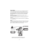
General Handling Precautions Before starting work or operation, be sure to check that the instrument is functioning correctly with normal performance. Do not submerge the instrument into water. The instrument can not be submerged underwater. The instrument is designed based on the International Standard IP66, therefore it is protected from the normal rainfall. Setting the instrument on a tripod When mounting the instrument on a tripod, use a wooden tripod when possible.
Notice on Transceiver When using high output transceiver etc., make sure it does not come near the instrument. Opening the carrying case When opening the carrying case and taking out the instrument, place the case horizontally, then open the case.
Display for Safe Use In order to encourage the safe use of products and prevent any danger to the operator and others or damage to properties, important warnings are put on the products and inserted in the instruction manuals. We suggest that everyone understand the meaning of the following displays and icons before reading the “Safety Cautions” and text Display Meaning WARNING Ignoring or disregard of this display may lead to the danger of death or serious injury.
•Battery can cause explosion or injury. Do not dispose in fire or heat. •Risk of fire or electric shock. Do not use any power voltage except the one given on manufacturers instructions. •Battery can cause outbreak of fire. Do not block up the vent of the battery. •The short circuit of a battery can cause a fire. Do not short circuit battery when storing it. CAUTION Use of controls or adjustment or performance of procedures other than those specified herein may result in hazardous radiation exposure.
Laser Safety DT-205L/207L/209L uses the visible laser beam. DT-205L/207L/209L products are manufactured and sold in accordance with “Radiation Safety of Laser Products, Equipment Classification, Requirements and User‘s Guide” (IEC Publication 60825-1) or “Performance Standards for Light-Emitting Products” (FDA/BRH 21 CFR 1040) provided on the safety standards for laser beam. As per the said standards, DT-205L/207L/209L classified as “Class 2 (CLASS II) Laser Products”.
User 1) This product is for professional use only! The user is required to be a qualified surveyor or have a good knowledge of surveying, in order to understand the user and safety instructions, before operating, inspecting or adjusting. 2) Wear the required protectors (safety shoes, helmet, etc.) when operating. Exceptions from Responsibility 1) The user of this product is expected to follow all operating instructions and make periodic checks of the product’s performance.
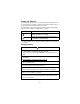
Contents FOREWORD ........................................................................................................ 1 General Handling Precautions ................................................................... 2 Display for Safe Use .................................................................................. 4 Safety Cautions ......................................................................................... 4 Laser Safety .............................................................
Standard Set Composition The numerical value in parentheses shows the quantity. Instrument (1) Carrying case(1) (with lens cap) Plumb bob set (1) Tool kit (1) Cleaning brush, Screw driver, Rod pins, Plumb bob hook (Hexagonal wrench : Only for DT-205/207/209/209P) AA batteries (4) Plastic rain cover (1) Silicon cloth (1) Instruction manual (1) • Make sure that all of the above items are with the instrument when purchased.
1 NOMENCLATURE AND FUNCTIONS 1.1 Nomenclature Sighting collimator DT-205/207/209/209P Instrument height mark Objective lens Display window *1) Horizontal tangent screw Optical plummet telescope Tribrach fixing lever (205/207 only) Circular level Horizontal motion clamp *1) DT-209/209P has one side display only.
Handle Handle fixing knob Telescope focusing knob Cross-hair adjustment section cover Telescope eyepiece Battery Vertical motion clamp Vertical tangent screw Plate level Operation keys Base RS-232C Connector (205 only) Tribrach type DT-205/207: Detachable DT-209: Fixing DT-209P: Centering Plate level (207 only) 11
DT-205L/207L/209L Sighting collimator Instrument height mark Objective lens Horizontal motion clamp Horizontal tangent screw Optical plummet telescope Display window *1) Leveling screw Circular level Tribrach fixing lever (205L/207L only) *1) DT-209L has one side display only.
Handle Handle fixing knob Telescope focusing knob Cross-hair adjustment section cover Telescope eyepiece Battery Vertical motion clamp Vertical tangent screw Laser axis adjusting screw (with cap) Plate level Operation keys Base Tribrach type DT-205L/207L: Detachable DT-209L: Fixing RS-232C Connector (205L only) Plate level (207L only) 13
1.2 Display Display marks Display V Contents Display Contents Tilt correction mode (DT-205/205L only) TILT Vertical angle HR Horizontal angle right F Function key selection mode HL Horizontal angle left % Percent grade Ht Repetition angle measurement G Unit display GON 8AVG The number of repetition / Average of angle 1.
Adjustment mode and Selecting mode Mode Key Adjustment mode of vertical angle 0 datum Turn the power ON while pressing the [0 SET] key. Turn the power ON while pressing the [R/L] key. Turn the power ON while pressing the [V/%] key.
2 PREPARATION FOR MEASUREMENT 2.1 Setting Instrument Up for Measurement Setting up the Tripod First, extend the extension legs to suitable lengths and tighten the screws on their midsections. Attaching the Instrument on the Tripod Head Place the instrument carefully on the tripod head and slide the instrument by loosening the tripod screw. If the plumb bob is positioned right over the center of the point, slightly tighten the tripod screw.
Centering by Using the Plate Level 1) Rotate the instrument horizontally by using the Horizontal motion/clamp screw and place the plate level parallel with the line connecting leveling screws A and B, and then bring the bubble to the center of the plate level by turning leveling screws A and B. Leveling screw A Leveling screw B 2) Rotate the instrument 90° (100g) around its vertical axis and turn the remaining leveling screw or C to center the bubble once more.
2.2 Power Switch Key ON 1 Confirm the instrument is leveled. 2 Turn the power switch ON. Every segment turns on for about 1 second. HR 342°03’41” Battery Power Remaining Display 3 Press the [V/%] key. The vertical angle is displayed. V HR 11°50’28” 342°03’41” ● Confirm the battery power remaining on the display. Replace with charged battery or charge when battery level is low. Refer to Section 2.3 “Battery Level Indicator” .
2.3 Battery Level Indicator The battery power indicator shows the level of battery strength. V HR 90°10’20” TILT 123°40’50” Measurement is possible. Battery Power Remaining Display Measurement is impossible. Need to recharge or replace the battery. 1) The battery operating time will vary depending on the environmental conditions, such as ambient temperature etc. It is recommended for safety to prepare spare batteries. 2) For general usage of battery, see chapter 7 “HANDLING POWER SOURCE” 2.
3 MEASUREMENT 3.1 Measuring Horizontal Angle Right and Vertical Angle 1 Collimate the first target "A". V HR 90°10’20” 120°30’40” 2 Press the [0 SET] key twice to set the horizontal angle of target "A" at 0° 00' 00". V HR 90°10’20” 0°00’00” • One time pressing [0 SET] function is available. Refer to "6 SELECTING MODE". 3 Collimate the second target "B". The required H/V angle to target B will be displayed.
3.2 Switching Horizontal Angle Right / Left 1 Collimate the first target "A". V HR 90°10’20” 120°30’40” 2 Press the [R/L] key. The mode Horizontal angle right (HR) switches to Horizontal angle left (HL) V H L 90°10’20” 239°29’20” • Every time pressing the [R/L] key, HR/HL mode switches. 3 Measure as HR mode. Reference : How to Collimate 1 Point the telescope toward the light. Turn the diopter ring and adjust the diopter so that the cross hairs are clearly observed.
3.3 Measuring from the Required Horizontal Angle 1 Display the required horizontal angle using the horizontal motion clamp and horizontal tangent screw. V HR 90°10’20” 130°40’20” 2 Press the [HOLD] key. The display of horizontal angle blinks and the horizontal angle will be held. V HR 90°10’20” 130°40’20” blinks • To return to the angle status before the data is held, press any key except the [HOLD] key. 3 Collimate the target to set. 4 Press the [HOLD] key.
3.5 Repetition Angle Measurement 1 Press the [FUNC] key. F V 90°10’20” HR 120°30’40” 2 Press the [REP] key. Ht 0°00’00” 0 H 3 Collimate the target "A", and press the [0SET] key twice. Ht 0°00’00” 0 H 4 Collimate the target "B", and press the [HOLD] key. Ht 45°10’00” 1AVG H 45°10’00” 5 Recollimate the target "A" and press the [R/L] key. 6 Recollimate the target "B", and press the [HOLD] key.
7 Repeat the procedure 5 and 6 to measure the desired number of repetition. Ht 180°40’00” 4AVG H 45°10’00” Example: 4 measurements 8 To finish the repetition measurement, press the [FUNC] key and press the [HOLD] key. • Horizontal angle can be accumulated up to (2000°00'00" – minimum reading) (horizontal angle right). In case of 5 second reading, horizontal angle can be accumulated up to +1999°59'55". • When the discrepancy value of each measuring is more than ±30", the error code “E04” is displayed.
3.6 Stadia Surveying This instrument can be used for stadia surveying, Measurement by stadia is a convenient method for measuring distances with the stadia hairs of the instrument, in combination with a graduated rod, such as a leveling rod or stadia rod, which is preferable for long distances. The distance from the center of the instrument to the rod is found by sighting through the instrument on the rod and multiplying the stadia interval by 100.
4 HOW TO OPERATE THE LASER (DT-205L/207L/209L only) WARNING Aiming the instrument into prism or highly reflective surface can result in serious damage to your eye because the optical axis and laser beam source is in coincidence. Do not aim the instrument directly into prism or highly reflective surface. Do not look at the laser beam directly. •Laser beams can be dangerous, and can cause eye injury's if used incorrectly. Never attempt to repair the instrument yourself. 1 Collimate a target.
5 THE OTHER FUNCTIONS 5.1 Buzzer Sounding for Horizontal Angle 90° Increments When the horizontal angle falls in the range of less than ± 1° of 0°, 90°, 180° or 270°, the buzzer sounds. Buzzer stops only when the horizontal angle is adjusted to 0°00’00”, 90°00’00” , 180°00’00” or 270°00’00”. To stop the buzzer sounding, refer to "6 SELECTING MODE" . 5.2 Compasses (vertical angle) Vertical angle scale is displayed as shown below. To set this function, refer to "6 SELECTING MODE". +90° 0° 0° -90° 5.
5.5 Detach / Attach of Tribrach Only for detachable tribrach type Alignment piece Tribrach alignment groove Securing screw Tribrach fixing lever The instrument is easily detached or attached to the tribrach, with a tribrach locking lever loosened or tightened for this purpose. ● Detachment 1 Loosen the tribrach locking lever, by revolving it 180° or 200g in the counterclockwise direction (which will point the triangle mark upwards).
6 SELECTING MODE The following modes are available 6.1 Items of the Selecting Mode Selecting mode 1 To set the instrument the selecting mode 1, turn the power ON while pressing the [R/L] key. Selecting mode 1 [R/L] key + Power on 0 0 0 0 0 0 0 Digit No.7 Digit No.1 Selecting mode 1 Digit No. 1 Items Minimum angle unit Contents Select the minimum angle unit.
Selecting mode 2 To set the instrument the selecting mode 2, turn the power ON while pressing the [V/%] key. Selecting mode 2 [V/%] key + Power on 0 0 0 0 0 0 0 Digit No.7 Digit No.1 Selecting mode 2 Digit No. Items Contents Setting value = 0 Setting value = 1 1 [0 SET] key pressing once / twice Choose once or twice for pressing the [0 SET] key. Twice Once 2 Compass ON/OFF Set the function of compass (Vertical angle scale).
6.2 How to Set the Selecting Modes ● Selecting Mode 1 Sample setting: Auto cut off : OFF, 90° buzzer : OFF 1 Turn the power ON while pressing the [R/L] key. The instrument will be in the selecting mode 1, and the digit No.1 will blink. Blinking 0 0 0 0 0 0 0 Digit No.7 Digit No.1 2 Let the digit No.3 to be set blink by pressing the [ ] key. 0 0 0 0 0 0 0 Blinking ● Pressing the [ 3 Press the [ ] key, blinking digit moves to the right. ] key to set 1 for the digit.
6 Press the [0 SET] key to set the setting. S E T 0 1 0 0 1 0 0 7 Turn the power off.
● Selecting mode 2 Sample setting: [0 SET] key pressing : Once, Tilt correction : OFF 1 Turn the power ON while pressing the [V/%] key. The instrument will be in the selecting mode 2, and the digit No.1 ( 0set key pressing) will blink. 0 0 1 0 0 0 0 Blinking 2 Press the [ ] key to set 1 for the digit. 0 0 1 0 0 0 1 ● Every time pressing the [ ] key, the blinking digit value 0/1 switches. 3 Let the digit No.4 (Tilt correction) to be set blink by pressing the [ ] key.
7 HANDLING POWER SOURCE 7.1 For removing 1 Push the lock lever downward and pull out the battery. Lock lever 7.2 Replace the battery (DB-35) Hole Lid Convex Lid Hook 1 Push the hook downward and take the lid out. 2 Take out the old batteries and put new batteries as illustration shows in direction of plus and minus sides 3 Insert a convex in a upper hole. Click to close the lid by pressing it. ● Replace all four batteries to new ones at the same time. ● Do not mix the old batteries to the new ones.
8 CHECK AND ADJUSTMENT ● Pointers on the Adjustment 1 Adjust the eyepiece of the telescope properly prior to any checking 2 3 4 5 operation which involves sighting through the telescope. Remember to focus properly, with parallax completely eliminated. Carry out the adjustments in the order of item numbers, as the adjustments are dependent one upon another. Adjustments carried out in the wrong sequence may even nullify previous adjustment.
8.1 Checking /Adjusting the Plate Level Adjustment is required if the axis of the plate level is not perpendicular to the vertical axis. ● Checking 1 Place the plate level parallel to a line running through the centers of two leveling screws, say, A and B. Use these two leveling screws only and place the bubble in the center of the plate level. 2 Rotate the instrument 180° or 200g around the vertical axis and check bubble movement of the plate level.
8.2 Checking and Adjusting the Circular Level ● Checking 1 Carefully level the instrument with the plate level only. If the bubble of the circular level is centered properly, adjustment is not required. Otherwise, proceed with the following adjustment. ● Adjustment 1 Shift the bubble to the center of the circular level, by adjusting three capstan adjustment screws on the bottom surface of the circular level, with the accessory adjusting pin.
8.3 Adjustment of the Vertical Cross-hair Adjustment is required if the vertical cross-hair is not in a place perpendicular to the horizontal axis of the telescope ( since it must be possible to use any point on the hair for measuring horizontal angles or running lines). ● Checking 1 Set the instrument up the tripod and carefully level it. 2 Sight the cross-hairs on a well defined Point A at a distance of, at least, 50 meters (160ft.) and clamp horizontal motion.
3 Check once more and if the point travels the entire length of the vertical cross-hair, further adjustment is not required. Eyepiece section attachment screws Eyepiece Perform following adjustment after completing the above adjustment . Section 8.4 “Collimation of the Instrument”, Section 8.6 “Adjustment of Vertical Angle 0 Datum”.
8.4 Collimation of the Instrument Collimation is required to make the line of sight of the telescope perpendicular to the horizontal axis of the instrument, otherwise, it will not be possible to extend a straight line by direct means. ● Checking Eyepiece 1 Set the instrument up with clear sights of about 50 to 60meters 50 (160 to 200 ft.) on both sides of the instrument. 2 Level the instrument Telescope properly with the plate level. 3 Sight Point A at approximately 50 meters 50 (160 ft.) distance.
● Adjustment 1 Unscrew the cross-hair adjustment section cover. 2 Find Point D at a point between Points C and B, which should be equal to 1/4th the distance between Points B and C and measured from Point C. This is because the apparent error between Points B and C is four times the actual error since the telescope has been reversed twice during the checking operation.
8.5 Checking and Adjusting the Optical Plummet Telescope Adjustment is required to make the line of sight of the optical plummet telescope coincide with the vertical axis ( otherwise the vertical axis will not be in the true vertical when the instrument is optically plumbed). ● Checking 1 Coincide the center mark and the point. (See Chapter 2 “PREPARATION FOR MEASUREMENT” .) 2 Rotate the instrument 180° or 200g around the vertical axis and check the center mark.
8.6 Adjustment of Vertical Angle 0 Datum If when measuring the vertical angle of target A at telescope position normal (direct) and reverse settings, the amount of normal and reverse measurements combined is other than 360° (ZENITH-0), half of the difference from 360° is the error amount from corrected 0 setting. Carry out adjustment. As adjustment for vertical angle 0 setting is the criteria for determining instrument coordinate origin, use special care for adjustment.
8.7 Adjustment of Laser Beam This adjustment must be done after completing following checking and adjusting. 8.3 “Adjustment of the Vertical Cross-hair”, 8.4 “Collimation of the Instrument”. WARNING ● Aiming the instrument into prism or highly reflective surface can result in serious damage to your eye because the optical axis and laser beam source is in coincidence. Do not aim the instrument directly into prism or highly reflective surface. Do not look at the laser beam directly.
9 STORAGE PRECAUTIONS ● When returning the instrument to its case, be sure to match the white positioning marks provided with the case and place the instrument with the eyepiece upward. ● For cleaning the instrument after use, remove dust using a cleaning brush, then wipe off with a cloth. ● For cleaning the lens surface, use a cleaning brush to remove the dust, then use a clean lintless cotton cloth. Moisten it with alcohol (or mixture with ether) to wipe gently in a rotational motion from the center out.
10 OPTIONAL ACCESSORIES Diagonal Eyepiece, Model 13 The diagonal eyepiece is used in place of the telescope eyepiece for making observations up to the zenith. Instrument eyepiece Diagonal eyepiece, model 13 Trough Compass model 5 The trough compass is simply mounted on top of the carrying handle. Back pack When transporting the instrument with this back pack, it is very convenient for carrying the instrument on the shoulder.
11 ERROR DISPLAY Display Contents Countermeasure AnGLE Error Displayed when the instrument or the telescope rotated quickly. In this case, it is not failure. However, repair is required when "AnGLE Error" is displayed frequently. E04 Displayed when the discrepancy value of each measuring is more than ±30” while repetition angle measurement is operated. Press the [0SET] key, measure again from the beginning. E70 When "Adjustment of Vertical Angle 0 datum" is adjusted in wrong procedure.
12 SPECIFICATIONS (DT-205/207/209/209P) Model Item Telescope Electronic Angle Measurement Item DT-205 DT-207 DT-209/ 209P Length 149mm 149mm 149mm Objective lens 45mm 45mm 40mm Magnification 30× 30× 26× Image Erect Erect Erect 1° 30' Field of view 1° 30' 1° 30' Resolving power 2.5" 2.5" 3" Minimum focus 0.9m 0.9m 0.
Model Item Item Others Dimension DxWxH(mm) DT-205 DT-207 DT-209/ 209P 149x188x313 149x188x313 (5.87x7.1x12.3 in) (5.87x7.1x12.3 in) Weight (Including batteries) 4.1kg 4.1kg (9.0 lb) (9.0 lb) DT-209: 3.4kg (7.5 lb) DT-209P: 3.8kg (8.3 lb) Instrument height 176 mm 176 mm ------- (6.93 in) (6.93 in) Yes No DT-205L DT-207L DT-209L Serial signal RS-232C connector DT-209: 149x188x305 (5.87x7.1x12.0 in) DT-209P: 149x188x313 (5.87x7.1x12.
Item Item Optical Plummet Telescope Model DT-205L DT-207L DT-209L Magnification 3x 3x 3x Filed of view 3° 3° 3° Focusing 0.5m~∞ 0.5m~∞ 0.5m~∞ Level Sensitivity Plate level 40"/2 mm 40"/2 mm 60"/2 mm Circular level 10'/2mm 10'/2mm 10'/2mm Water protection Standard IP 66 IP 66 IP 66 Power Supply Battery 4 AA batteries 4 AA batteries 4 AA batteries Operating Time (Alkaline manganese dry batteries), (+20°C [+68°F]Åj Theodolite only Approx. 140 Approx. 150 Approx.
TOPCON POSITIONING SYSTEMS, INC. 5758 West Las Positas Blvd., Pleasanton, CA 94588, U.S.A. Phone: 925-460-1300 Fax: 925-460-1315 www.topcon.com TOPCON CALIFORNIA 3380 Industrial Blvd, Suite 105, West Sacramento, CA 95691, U.S.A. Phone: 916-374-8575 Fax: 916-374-8329 TOPCON MIDWEST 891 Busse Road, Elk Grove Village, IL 60007, U.S.A. Phone: 847-734-1700 Fax: 847-734-1712 TOPCON EUROPE B.V. Essebaan 11, 2908 LJ Capelle a/d IJssel, The Netherlands. Phone: 010-4585077 Fax: 010-4585045 www.topconeurope.