Before using the projector, please read this operation manual carefully. ENGLISH Introduction IMPORTANT For your assistance in reporting the loss or theft of your Projector, please record the Serial Number located on the bottom of the projector and retain this information. Before recycling the packaging, please ensure that you have checked the contents of the carton thoroughly against the list of “Supplied accessories” on page 5. Model No.: DT-400 Serial No.
PRODUCT DISPOSAL This projector utilises tin-lead solder, and a pressurised lamp containing a small amount of mercury. Disposal of these materials may be regulated due to environmental considerations. For disposal or recycling information, please contact your local authorities or, if you are located in the United States of America, the Electronic Industries Alliance: www.eiae.org . Declaration of Conformity SHARP PROJECTOR, MODEL DT-400 This device complies with Part 15 of the FCC rules.
Introduction WARNING: Some IC chips in this product include confidential and/or trade secret property belonging to Texas Instruments. Therefore you may not copy, modify, adapt, translate, distribute, reverse engineer, reverse assemble or discompile the contents thereof. This SHARP projector uses a DMD panel. This very sophisticated panel contains 921,600 pixels micromirrors.
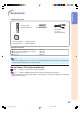
Contents Preparing Introduction Contents .......................................................... 4 Accessories .................................................... 5 IMPORTANT SAFEGUARDS .......................... 6 Part Names and Functions ............................ 9 Using the Remote Control ........................... 13 Usable Range .................................................... 13 Inserting the Batteries ....................................... 13 Quick Start Quick Start ....................
Introduction Accessories Supplied accessories Remote control RRMCGA334WJSA Two AA size batteries Power cord (6' (1.8 m)) QACCDA007WJPZ Operation manual TINS-B532WJZZ Lens cap (attached) PCAPHA021WJSA Optional accessories ■ ■ ■ ■ 3 RCA to 15-pin D-sub cable (9'10" (3.0 m)) DVI to 15-pin D-sub adaptor (7.9" (20 cm)) DVI cable (9'10" (3.0 m)) Lamp unit AN-C3CP AN-A1DV AN-C3DV AN-K2LP Note • Some of the optional accessories may not be available depending on the region.
IMPORTANT SAFEGUARDS CAUTION: Please read all of these instructions before you operate this product and save these instructions for later use. Electrical energy can perform many useful functions. This product has been engineered and manufactured to assure your personal safety. BUT IMPROPER USE CAN RESULT IN POTENTIAL ELECTRICAL SHOCK OR FIRE HAZARDS. In order not to defeat the safeguards incorporated in this product, observe the following basic rules for its installation, use and servicing. 1.
Introduction Ensure that you read the following safeguards when setting up your projector. Caution concerning the lamp unit ■ Potential hazard of glass particles if lamp ruptures. In case of lamp rupture, contact your nearest Sharp Authorized Service Center or Dealer for a replacement. See “Replacing the Lamp” on page 56.
IMPORTANT SAFEGUARDS Caution regarding usage of the projector ■ When using the projector, ensure not to subject it to hard impact and/or vibration, as this can result in damage. Take extra care with the lens. If you are not to use the projector for a long time, ensure to unplug the power cord from the wall outlet, and disconnect any other cables connected to it. ■ Do not use the projector by holding the lens.
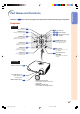
Numbers in Introduction Part Names and Functions refer to the main pages in this operation manual where the topic is explained. Projector Top View ON button 28 10 Turn the power on. STANDBY button 29 Put the projector into standby mode. RESIZE button Power indicator 10 54 Lamp indicator 10 54 Temperature warning indicator 34 Switch the picture display (STRETCH, SIDE BAR, etc.). 30 ENTER button Set items selected or adjusted on the menu.
Part Names and Functions About the Indicators on the Projector Power indicator Red on ... Normal (Standby) Green on ... Normal (Power on) Lamp indicator Green on ... Normal Green blinks ... The lamp is warming up or shutting down. Red on ... The lamp has been shut down abnormally or needs to be changed. (See page 54.) Temperature warning indicator Off ... Normal Red on ... The internal temperature is abnormally high. (See page 54.) -10 DT400_E_P06_15.p65 10 04.10.
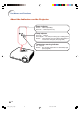
refer to the main pages in this operation manual where the topic is explained. Projector (Rear View) Terminals Refer to “INPUT Terminals and Connectable Main Equipment” on page 19. INPUT 2 terminal 21 24 Component signals. INPUT 1 terminal Connect video equipment. 21 Component signals. 24 Digital input type switch 22 23 INPUT 5/DIGITAL terminal 22 25 23 26 25 7 Rear adjustment feet RS-232C terminal (Serviceman only).
Part Names and Functions Numbers in refer to the main pages in this operation manual where the topic is explained. Remote Control STANDBY button 29 Put the projector into standby mode. KEYSTONE button 28 Turn the power on. 32 Enter the Keystone Correction mode. ENTER button 38 39 Set items selected or adjusted on the menu. UNDO button ON button MENU button Display adjustment and setting screens.
Remote control sensor Front View 30° Usable Range The remote control can be used to control the projector within the ranges shown in the illustration. Introduction Using the Remote Control 30° Remote control signal transmitters 30° 23' (7 m) Note • The signal from the remote control can be reflected off a screen for easy operation. However, the effective distance of the signal may differ depending on the screen material.
Quick Start This section shows the basic operation. For details, see the page described below for each step. Setup and Projection Connection of the projector and the video equipment with an S-video terminal is explained as an example below. 3 ON button 8 STNADBY button 8 STNADBY button 3 ON button 6 ZOOM/FOCUS button 7 KEYSTONE button 6 Adjustment buttons ('/"/\/|) 6, 7 Adjustment buttons ('/"/\/|) 4 INPUT button 6 ZOOM/FOCUS button 4 INPUT buttons, DIGITAL INPUT button 6 HEIGHT ADJUST button 1.
4. Select the INPUT mode Select the “INPUT 3” using the INPUT button on the projector or the INPUT 3 button on the remote control. " On-screen Display On the On the remote projector control • When pressing on the projector, input mode switches in order of : INPUT 2 INPUT 3 INPUT 4 INPUT 5 DIGITAL • When using the remote control, press / / / / / Quick Start INPUT 1 to switch the INPUT mode. Page 29 5. Turn the video equipment on and playback 6.
Setting Up the Projector Setting Up the Projector Position the projector perpendicular to the screen to achieve an optimal image. Note • The projector lens should be centered in the middle of the screen. If the horizontal line passing through the lens center is not perpendicular to the screen, the image will be distorted, making viewing difficult. • For an optimal image, position the screen so that it is not in direct sunlight or room light.
Screen Size and Projection Distance The projection screen size varies according to the distance from the lens of the projector to the screen. Install the projector so that projected images are projected onto the screen at the optimum size by referring to the table below. Use the values in the table as a reference when installing the projector. Side View Screen H Lens center Setup L When using a wide screen (16:9): In case of displaying the 16:9 picture on the whole of the 16:9 screen.
Setting Up the Projector Projecting a Reversed Image Projection from behind the Screen ■ Place a translucent screen between the projector and the audience. ■ Reverse the image by setting “Rear” in the “PRJ Mode” menu. (See page 52.) Translucent screen Audience Projection Using a Mirror ■ Place a mirror (normal flat type) in front of the lens. ■ When the translucent screen is placed between the mirror and audience, set to “Front” in the “PRJ Mode” menu. (See page 52.
Connections INPUT Terminals and Connectable Main Equipment INPUT 1, 2 terminal INPUT 5/DIGITAL terminal Connecting video equipment with component output terminal (DVD player, DTV decoder, DVD recorder with hard disc, etc.). (See pages 22, 23.) Connecting the computer. (See pages 25, 26.) Connecting video equipment with component output terminal (DVD player, DTV decoder, DVD recorder with hard disc, etc.). (See page 21.
Samples of Cables for Connection • For more details of connection and cables, refer to the opeation manual of the connecting equipment. • You may need other cables or connectors not listed below. Equipment Audio-visual equipment Terminal on connected equipment Component video output terminal Terminal on the projector Cable Component cable (commercially available) Terminal Dedicated cable attached to the connected equipment.
Connecting to Video Equipment Before connecting, ensure to unplug the power cord of the projector from the AC outlet and turn off the devices to be connected. After making all connections, turn on the projector and then the other devices. Ensure to read the operation manuals of the devices to be connected before making connections. When connecting the component video equipment to the component input terminal on the projector (INPUT 1 or INPUT 2) Analog component output terminal DVD Player,etc.
Connecting to Video Equipment When connecting the component video equipment to the DVI input terminal on the projector (INPUT 5) • Before connecting the cable, switch the digital input type switch to “VIDEO”. Analog component output terminal 1 DVD Player,etc.
When connecting the video equipment with DVI output terminal (DIGITAL INPUT) • Before connecting the cable, switch the digital input type switch to “VIDEO”. 1 DVD Player,etc. Switch to “VIDEO” DIGITAL terminal DVI output terminal DVI cable (sold separately: AN-C3DV) 2 3 Note Connections • Select DIGITAL mode when connecting to video equipment with the digital output terminal. (See page 29.) -23 DT400_E_P19_26.p65 23 04.10.
Connecting to Video Equipment When connecting video equipment with S-video output terminal (INPUT 3) S-video output terminal DVD Player,etc. INPUT 3 terminal 2 1 S-video cable (commercially available) When connecting video equipment with video output terminal (INPUT 4) Video output terminal DVD Player,etc. INPUT 4 terminal 2 1 Composite video cable (commercially available) -24 DT400_E_P19_26.p65 24 04.10.
Connecting to a Computer When connecting a computer, ensure that it is the last device to be turned on after all the connections are made. Connecting to a computer (INPUT 5) • Before connecting the cable, switch the digital input type switch to “PC”.
Connecting to a Computer When connecting a computer, ensure that it is the last device to be turned on after all the connections are made. Connecting to a computer with DIGITAL RGB output Terminal (DIGITAL) • Before connecting the cable, switch the digital input type switch to “PC”. Computer 1 Switch to “PC” INPUT 5 terminal DVI output terminal 2 DVI cable (sold separately: AN-C3DV) 3 Note • Select DIGITAL mode when connecting to digital output terminal of the computer. (See page 29.
Turning the Projector On/Off Connecting the Power Cord Supplied accessory Power cord (6' (1.8 m)) Plug the supplied power cord into the AC socket. Turning the Projector On Before performing the steps in this section, connect any equipment that you use with the projector. (See pages 19-26.) Remove the lens cap and press projector or on the on the remote control. • The power indicator illuminates green. • After the lamp indicator illuminates, the projector is ready to start operation.
Turning the Projector On/Off Turning the Power Off (Put- ting the Projector into Standby Mode) 1 STANDBY button Press on the projector or on the remote control, then press that button again while the confirmation message is displayed, to put the projector into standby mode. ▼On-screen Display STANDBY button 2 Unplug the power cord from the AC outlet after the cooling fan stops. Info • Do not unplug the power cord during projection or cooling fan operation.
Image Projection Switching the INPUT Mode Select the appropriate input mode for the connected equipment. INPUT 1, 2, 3, 4, 5 and DIGITAL INPUT button Press , , , , or on the remote control to select the input mode.
Image Projection Adjusting the Focus 1 2 Press on the remote control. Press \ or | on the remote control to adjust the focus. Adjustment buttons ('/"/\/|) ZOOM/FOCUS button Note • You can also adjust the focus by using and \ or | on the projector. Adjusting the Projected Image Size 1 2 Press on the remote control. Press ' or " on the remote control to adjust the zoom. ZOOM/FOCUS button Adjustment buttons ('/"/\/|) Note • You can also adjust the zoom by using and ' or " on the projector.
Using the Adjustment Feet Top View Side View The height of the projector can be adjusted using the adjustment feet at the front and rear of the projector when the screen is located higher than the projector, the screen is inclined or when the installation site is slightly inclined. Install the projector so that it is as perpen- Lens center dicular to the screen as possible. 1 Lift the projector to adjust its height while pressing the HEIGHT ADJUST button.
Image Projection Keystone Correction KEYSTONE button This function can be used to adjust the Keystone settings. Note • When the image is projected from a direction at an angle, the image becomes distorted trapezoidally. The function for correcting trapezoidal distortion is called Keystone Correction. 1 Press on the remote control to enter the Keystone Correction mode. 2 Press '/" to select “H Keystone” or “V Keystone”.
Placement of the Projected Image Using the Keystone Correction 3 Align the edge of the screen closest to the projector with the test pattern by adjusting the zoom and the adjsuter. (See pages 30 and 31.) Place the projector at a distance from the screen that allows images to be projected onto the screen by referring to “Screen Size and Projection Distance” on page 17.
Image Projection Selecting the Picture Mode You can select the picture setting (Memory) directly stored in “Picture Mode” on the “Picture” menu. Press on the remote control. • Each time the button is pressed while the display is on, the picture mode changes in order of: Memory OFF Memory 1 Memory 2 Memory 5 Memory 4 Memory 3 Note • This function can also be accessed from the OSD menu (see page 44).
Input signal STRETCH Output screen image SIDE BAR SMART STRETCH CINEMA ZOOM 4:3 aspect ratio 480I 480P 576I 576P NTSC PAL SECAM Letterbox Squeeze 16:9 aspect ratio 540P 1080I 16:9 aspect ratio Basic Operation 720P 16:9 aspect ratio VGA SVGA XGA 4:3 aspect ratio Note • “SMART STRETCH” cannot be selected while the Keystone correction (page 32) is being adjusted. • Keystone correction (page 32) is disabled while the picture mode is set to “SMART STRETCH”.
Menu Items The following shows the items that can be set in the projector. “Picture” menu Example: Screen for INPUT 1 mode Main Menu Picture Page 42 Sub Menu Contrast -30 +30 Bright -30 +30 Color -30 +30 Tint -30 +30 Sharp -30 +30 Red -30 +30 Blue -30 +30 *1 *1 *1 Reset Page 42 5500K 6500K 7500K 8500K 9300K 10500K CLR Temp Page 42 Example: Screen for INPUT 5 (RGB) mode Gamma Adj.
“Options” menu Example: Screen for INPUT 1 mode Main Menu Options Page 47 Sub Menu Lamp Timer (Life) Page 47 OSD Display [ON/OFF] Page 47 Video System *1 Page 48 Signal Type Page 48 *2 Auto PAL NTSC3.58 SECAM NTSC4.
Using the Menu Screen The menu can be operated to achieve two functions, adjustments and settings. (For setting the menu items, see pages 40 and 41. ) Adjustment buttons ('/"/\/|) ENTER button Adjustment buttons ('/"/\/|) MENU button UNDO button ENTER button MENU button UNDO button Menu Selections (Adjustments) • This operation can also be performed by using the buttons on the projector. 1 Press .
3 Press ' or " to select the item you want to adjust. • The selected item is highlighted. (Example: Selecting “Bright”) To adjust the projected image while viewing it Press . Single adjustment items • The selected single adjustment item (e.g. “Bright”) appears on the lower part of the screen. • When pressing ' or ", the next item will be displayed. (e.g. “Bright” is replaced with “Color” by pressing ".) Note • Press 4 to return to the previous screen. Press | or \ to adjust the item selected.
Using the Menu Screen The menu can be operated to achieve two functions, adjustments and settings. The “setting” item is displayed by or on the menu screen. (For adjusting the menu items, see pages 38 and 39.) Adjustment buttons ('/"/\/|) MENU button ENTER button UNDO button Menu Selections (Settings) • This operation can also be performed by using the buttons on the projector. 1 Press . • The “Picture” menu screen for the selected input mode is displayed.
3 Press ' or " to select the item you want to set, and then press | to display the sub menu. • The selected item is highlighted. (Example: Selecting “Menu Position”) Note • Press or \ to return to the previous screen. • For some items, press \ or | to select the icon using “ ”. 4 Press ' or " to select the setting of the item displayed in the sub menu. 5 Press . • The selected item is set. 6 Press . • The menu screen will disappear. Useful Features -41 DT400_E_P38_46.p65 41 04.10.
Picture Adjustment (“Picture” menu) You can adjust the projector’s picture to your preferences using the “Picture” menu. Adjusting the Image Adjusting the Color Temperature Menu operation This function allows for selecting the desired color temperature. With the lower value selected, the projected image becomes warmer, reddish and incandescent-like while with the higher value, the image becomes cooler, bluish and fluorescent-like.
Gamma Correction Function Emphasising the Contrast Gamma is an image quality enhancement function. Four gamma settings are available to allow for differences in the brightness of the room. This function emphasises the bright portions of images to obtain a higher contrast image.
Picture Adjustment (“Picture” menu) Picture Mode Function This function stores all items set in “Picture”. Five settings can be stored separately in “Memory 1” to “Memory 5”. Each stored setting is reassigned to each input mode (INPUT 1 to INPUT 5). Even when the input mode or signal is changed, you can easily select optimal settings from the stored settings. Menu operation Page 40 Switching the High Brightness/High Contrast Mode This function changes the brightness and contrast of the projected image.
Computer Image Adjustment (“Fine Sync” menu) You can adjust the computer image, match the computer display mode, and confirm the input signal using the “Fine Sync” menu. Adjusting the Computer Image Use the Fine Sync function in case of irregularities such as vertical stripes or flickering in portions of the screen.
Computer Image Adjustment (“Fine Sync” menu) Auto Sync Adjustment Checking the Input Signal Select whether the image is to be synchronized automatically when switching the signal with “ON” or “OFF”. This function allows you to check the current input signal information.
Using the “Options” Menu You can use the “Options” menu to enhance the usage for the projector. Checking the Lamp Life Status You can confirm the cumulative lamp usage time and the remaining lamp life (percentage). Menu operation Page 40 Example: “Options” menu screen for INPUT 1 mode Setting On-screen Display This function allows you to turn off the on-screen messages that appear during input select.
Using the “Options” Menu Setting the Video System Signal Type Setting The video input system mode is factory preset to “Auto”; however, a clear picture from the connected audio-visual equipment may not be received, depending on the video signal difference. In that case, switch the video signal. This function allows you to select the input signal type RGB or Component for INPUT 5.
Selecting a Background Image This function allows you to select the image displayed when no signal is being sent to the projector.
Using the “Options” Menu Auto Power Off Function Menu operation Page 40 Example: “Options” menu screen for INPUT 1 mode Selecting the Menu Screen Position This function allows you to select the desired position of the menu screen. Menu operation Page 40 Example: “Options” menu screen for INPUT 1 mode Description of Auto Power Off Selectable items Description The projector automatically enters the (ON) standby mode when no input signal is detected for 15 minutes or longer.
Selecting the Menu Color This function allows you to select the color of the menu screen. Menu operation Page 40 Example: “Options” menu screen for INPUT 1 mode Description of Menu Colors Selectable Items Description (Opaque) The menu is displayed opaquely. The menu is displayed (Translucent) translucently. The part of the menu on the image becomes transparent. Useful Features -51 DT400_E_P47_52.p65 51 04.10.
Selecting the On-screen Display Language and the Projection Mode Selecting the On-screen Display Language Setting the Projection Mode The projector can switch the on-screen display language among 11 languages: English, German, Spanish, Dutch, French, Italian, Swedish, Portuguese, Chinese, Korean or Japanese. This projector is equipped with a reverse/invert image function that allows you to reverse or invert the projected image for various applications.
Maintenance Cleaning the projector Cleaning the lens ■ Ensure to unplug the power cord before cleaning the projector. ■ The cabinet as well as the operation panel is made of plastic. Avoid using benzene or thinner, as these can damage the finish on the cabinet. ■ Do not use volatile agents such as insecticides on the projector. Do not attach rubber or plastic items to the projector for long periods.
Maintenance Indicators ■ The warning lights on the projector indicate problems inside the projector. ■ If a problem occurs, either the temperature indicator or the lamp indicator will illuminate red, and the projector will enter the standby mode. After the projector has entered the standby mode, follow the procedures given below.
Maintenance indicator Abnormal Normal Problem Cause • Blocked air intake Temperature warning indicator Lamp indicator Off Possible solution • Relocate the projector to an area with proper ventilation (see page 7). The internal • Take the projector to your nearest Red on • Cooling fan breaktemperature is Sharp Authorized Service Center (Standby) down abnormally high. or Dealer for repair. • Internal circuit failure • Clean the exhaust and intake • Clogged air intake vents. (See page 53.
Regarding the Lamp Lamp ■ It is recommended that the lamp (optional: AN-K2LP) be replaced when the remaining lamp life becomes 5% or less, or when you notice a significant deterioration in the picture and color quality. The lamp life (percentage) can be checked with the on-screen display. See page 47. ■ Purchase a replacement lamp of type AN-K2LP from your place of purchase, nearest Sharp Authorized Service Center or Dealer. IMPORTANT NOTE TO U.S.
Removing and Installing the Lamp Unit Warning! • During projector operation, the lamp unit is very hot. Do not remove the lamp unit from the projector right after use. The lamp and parts around the lamp will be very hot and may cause burn or injury. Info • Ensure to remove the lamp unit using the handle. Ensure not to touch the glass surface of the lamp unit or the inside of the projector. • To avoid injury to yourself and damage to the lamp, ensure to carefully follow the steps below.
Regarding the Lamp Handle 4 Remove the lamp unit. • Loosen the two securing screws from the lamp unit. Hold the lamp unit by the handle and pull it in the direction of the arrow. At this time, keep the lamp unit horizontal and do not tilt it. 5 Insert the new lamp unit. Securing screws • Press the lamp unit firmly into the lamp unit compartment. Fasten the securing screws. 6 Replace the lamp unit cover. • Align the lamp unit cover and slide it to close.
Connecting Pin Assignments DVI-I (INPUT 5) port : 29 pin connector • DVI Digital INPUT 9 ••••••••• 1 2 •••• ~ • • • • • • • • • 16 ~ •••• 7 8 C1 C2 C4 C5 C3 17 24 18 •••• ~ • • • • 23 Pin No. 1 2 3 4 5 6 7 8 9 10 11 12 13 14 15 • DVI Analog RGB Input Pin No. 1 2 3 4 5 6 7 8 9 10 11 12 13 14 15 Signal Not connected Not connected Not connected Not connected Not connected DDC clock DDC data Vertical sync Not connected Not connected Not connected Not connected Not connected +5V power Ground Pin No.
Computer Compatibility Chart The table below lists signal codes that are compatible with the projector. When the images are distorted or cannot be projected, adjust the output signal of your computer and so forth while referring to the table below. Computer • Horizontal Frequency: 15–70 kHz Vertical Frequency: 43–75 Hz Pixel Clock: 12–80 MHz Compatible with sync on green XGA compatible in intelligent compression PC/ MAC/ WS Resolution Horizontal Frequency (kHz) Vertical Frequency (Hz) 27.0 60 31.5 27.
Troubleshooting Problem Check • Projector power cord is not plugged into the wall outlet. • Power to the external connected devices is off. • The selected input mode is wrong. • Cables are incorrectly connected to the rear panel of the projector. • External output has not been set when connecting notebook computer. • “Contrast” and “Bright” are set to minimum position. • Image adjustments are incorrectly set. (Video Input only) • Video input system is incorrectly set.
Specifications Product type Projector Model DT-400 Video system PAL/PAL 60/PAL-M/PAL-N/SECAM/NTSC 3.58/NTSC 4.43 DTV 480I/480P/720P/1080I Display method Single Panel Digital Micromirror Device (DMD™) by Texas Instruments DLP panel Panel size: 0.8" Drive method: Digital Light Processing (DLP™) No. of dots: 921,600 dots (1,280 [H] ⳯ 720 [V]) Lens 1–1.5 ⳯ zoom lens, F2.0–2.5 f=21.3–31.6 mm Projection lamp 275 W DC lamp Video input signal RCA Connector: VIDEO (INPUT 4), composite video, 1.
Dimensions Units: inches (mm) Side View (1.5) Rear View Side View 9/64 (3.25) 11 7/64 (282) 1/16 Top View 12 7/32 (310) 2 3/16 (55.5) 3 33/64 (89) 13/64 (5) Front View 1 59/64 (48.5) 2 11/64 (55.05) 3 15/16 (99.95) 5 7/64 (129.5) 5 7/64 (129.5) 7 1 5/32 1 /32 (29.1) (30.9) M4 M4 5/8 9/16 (14) (15.5) 8 7/8 (225.3) 8 9/32 (210.3) M4 Appendix M4 4 3/16 (106.3) Bottom View 1 7/32 1 3/4 (44.1) (30.9) -63 DT400_E_P61_68.p65 63 04.10.
Glossary Aspect Ratio Intelligent compression and expansion Width and height ratio of an image. The normal aspect ratio of a computer and video image is 4:3. There are also wide images with an aspect ratio of 16:9 and 21:9. Auto Sync Optimizes projected computer images by automatically adjusting certain characteristics. Background Initial setting image projected when no signal is being output. Clock Clock adjustment is used to adjust vertical noise when clock level is incorrect.
Index A M AC socket ............................................................. 27 Adjustment buttons .............................................. 38 Aspect ratio .......................................................... 35 Auto Power Off ..................................................... 50 Auto Sync ............................................................. 46 AUTO SYNC button ............................................. 46 MENU button .......................................................
VALID IN USA ONLY CONSUMER LIMITED WARRANTY SHARP ELECTRONICS CORPORATION warrants to the first consumer purchaser that this Sharp brand product (the “Product”), when shipped in its original container, will be free from defective workmanship and materials, and agrees that it will, at its option, either repair the defect or replace the defective Product or part thereof with a new or remanufactured equivalent at no charge to the purchaser for parts or labor for the period(s) set forth below.
VALID IN CANADA ONLY LIMITED WARRANTY Consumer Electronics Products Congratulations on your purchase! Sharp Electronics of Canada Ltd. (hereinafter called “Sharp”) gives the following express warranty to the first consumer purchaser for this Sharp brand product, when shipped in its original container and sold or distributed in Canada by Sharp or by an Authorized Sharp Dealer: Sharp warrants that this product is free, under normal use and maintenance, from any defects in material and workmanship.