XV-Z2000 DT-400 SERVICE MANUAL SERVICE-ANLEITUNG SY4C6XV-Z2000 PROJECTOR PROJEKTOR MODELS MODELLE XV-Z2000 DT-400 In the interests of user-safety (Required by safety regulations in some countries) the set should be restored to its original condition and only parts identical to those specified should be used. Im lnteresse der Benutzersicherheit (erforderliche Sicherheitsregeln in einigen Ländern) muß das Gerät in seinen Originalzustand gebracht werden.
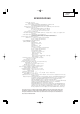
XV-Z2000 DT-400 CONTENTS Page Page • • • • • BLOCK DIAGRAM .......................................... 88 OVERALL WIRING DIAGRAM ....................... 90 WAVEFORMS ................................................. 92 PRINTED WIRING BOARD ASSEMBLIES .... 93 PARTS LIST Ë ELECTRICAL PARTS ............................... 101 Ë CABINET AND MECHANICAL PARTS .... 114 Ë ACCESSORIES PARTS ........................... 118 Ë PACKING PARTS ..................................... 118 • PACKING OF THE SET ..............
XV-Z2000 DT-400 SPECIFICATIONS Product type Projector Model XV-Z2000, DT-400 Video system PAL/PAL 60/PAL-M/PAL-N/SECAM/NTSC 3.58/NTSC 4.43 DTV 480I/480P/540P/576I/576P/720P/1080I Display method Single Panel Digital Micromirror Device (DMD™) by Texas Instruments DLP panel Panel size: 0.8" Drive method: Digital Light Processing (DLP™) No. of dots: 921,600 dots (1,280 [H] ⋅ 720 [V]) Lens 1–1.5 ⋅ zoom lens, F2.0–2.5 f=21.3–31.
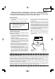
XV-Z2000 DT-400 IMPORTANT SERVICE SAFETY NOTES (for USA) Ë Service work should be performed only by qualified service technicians who are thoroughly familiar with all safety checks and servicing guidelines as follows: » Use an AC voltmeter with sensitivity of 5000 ohm per volt., or higher, sensitivity to measure the AC voltage drop across the resistor (See Diagram). » All checks must be repeated with the AC plug connection reversed.
XV-Z2000 DT-400 PRECAUTIONS A PRENDRE LORS DE LA REPARATION Ë Ne peut effectuer la réparation qu' un technicien spécialisé qui s'est parfaitement accoutumé à toute vérification de sécurité et aux conseils suivants. AVERTISSEMENT • Utiliser un voltmètre CA d'une sensibilité d'au moins 5000Ω/V pour mesurer la chute de tension en travers de la résistance.
XV-Z2000 DT-400 NOTE TO SERVICE NOTE POUR LE PERSONNEL PERSONNEL D’ENTRETIEN 123456789012345678901234567890121234567890123456 123456789012345678901234567890121234567890123456 123456789012345678901234567890121234567890123456 123456789012345678901234567890121234567890123456 123456789012345678901234567890121234567890123456 123456789012345678901234567890121234567890123456 UV-RADIATION PRECAUTION 123456789012345678901234567890121234567890123456 123456789012345678901234567890121234567890123456 PRECAUTION POUR
XV-Z2000 DT-400 123456789012345678901234567890121234567890123456 123456789012345678901234567890121234567890123456 123456789012345678901234567890121234567890123456 123456789012345678901234567890121234567890123456 UV-RADIATION PRECAUTION (Continued) 123456789012345678901234567890121234567890123456 123456789012345678901234567890121234567890123456 PRECAUTION POUR LES RADIATIONS UV (Suite) 123456789012345678901234567890121234567890123456 123456789012345678901234567890121234567890123456 Remplacement de la la
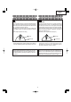
XV-Z2000 DT-400 WARNING: High brightness light source, do not stare into the beam of light, or view directly. Be especially careful that children do not stare directly in to the beam of light. WARNING: TO REDUCE THE RISK OF FIRE OR ELECTRIC SHOCK, DO NOT EXPOSE THIS UNIT TO MOISTURE OR WET LOCATIONS. CAUTION The lighting flash with arrowhead within a triangle is intended to tell the user that parts inside the product are risk of electric shock to persons. RISK OF ELECTRIC SHOCK.
XV-Z2000 DT-400 Precautions for using lead-free solder 1 Employing lead-free solder "PWBs" of this model employs lead-free solder. The LF symbol indicates lead-free solder, and is attached on the PWBs and service manuals. The alphabetical character following LF shows the type of lead-free solder. Example: LFa Indicates lead-free solder of tin, silver and copper. 2 Using lead-free wire solder When fixing the PWB soldered with the lead-free solder, apply lead-free wire solder.
XV-Z2000 DT-400 OPERATION MANUAL Projector Top View ON button Turn the power on. Power indicator STANDBY button Lamp indicator Put the projector into standby mode. Temperature warning indicator RESIZE button Switch the picture display (STRETCH, SIDE BAR, etc.). ZOOM/FOCUS button Adjust the projected image size or adjust the focus. ENTER button Set items selected or adjusted on the menu. UNDO button Undo an operation or returning to the previous display.
XV-Z2000 DT-400 About the Indicators on the Projector Power indicator Red on ... Normal (Standby) Green on ... Normal (Power on) Lamp indicator Green on ... Normal Green blinks ... The lamp is warming up or shutting down. Red on ... The lamp has been shut down abnormally or needs to be changed. Temperature warning indicator Off ... Normal Red on ... The internal temperature is abnormally high.
XV-Z2000 DT-400 Projector (Rear View) Terminals INPUT 2 terminal INPUT 4 terminal Component signals. INPUT 1 terminal Connect video equipment. Component signals. INPUT 3 terminal Connect video equipment with an S-video terminal. Digital input type switch INPUT 5/DIGITAL terminal RS-232C terminal Control the projector using a computer. Exhaust vent The speed and pitch of the cooling fan may change during operation in response to internal temperature changes.
XV-Z2000 DT-400 Remote Control STANDBY button Put the projector into standby mode. ON button Turn the power on. KEYSTONE button Enter the Keystone Correction mode. MENU button Display adjustment and setting screens. ENTER button Adjustment buttons ('/"/\/|) Set items selected or adjusted on the menu. UNDO button Undo an operation or returning to the previous display. ZOOM/FOCUS button Adjust the projected image size or adjusting the focus.
XV-Z2000 DT-400 Remote control sensor Front View 30° Usable Range 30° Remote control signal transmitters The remote control can be used to control the projector within the ranges shown in the illustration. 30° 23' (7 m) Note • The signal from the remote control can be reflected off a screen for easy operation. However, the effective distance of the signal may differ depending on the screen material.
XV-Z2000 DT-400 Connection Pin Assignments DVI-I (INPUT 5) port : 29 pin connector • DVI Digital INPUT ~ 9 Pin No. 1 2 3 4 5 6 7 8 9 10 11 12 13 14 15 16 ∞ ∞ ∞ ∞ ∞ ∞ ∞ ∞ ∞∞ ∞ ∞ ∞ ∞ ∞ ∞ ∞ ∞ 1 2 ~ ∞∞∞∞ 7 8 ∞∞∞∞ C1 C2 C4 C5 C3 17 24 18 ~ ∞ ∞ ∞ ∞ 23 ∞∞∞∞ • DVI Analog RGB Input Pin No.
XV-Z2000 DT-400 DIMENSIONS Units: inches (mm) Side View /16 (1.5) Rear View Side View 9/64 (3.25) 11 7/64 (282) 1 Top View 12 7/32 (310) 2 3/16 (55.5) 3 33/64 (89) /64 (5) Front View 1 59/64 (48.5) 2 11/64 (55.05) 13 3 15/16 (99.95) 5 7/64 5 7/64 (129.5) (129.5) 7 1 5/32 1 /32 (29.1) (30.9) M4 M4 5 9 /16 (14) /8 (15.5) 1 7/32 1 3/4 (44.1) (30.9) 16 8 7/8 (225.3) M4 8 9/32 (210.3) M4 4 3/16 (106.
XV-Z2000 DT-400 REMOVING OF MAJOR PARTS 1. Removing the lamp unit cover and the lamp unit 1-1. Loosen the lamp unit cover fixing screw, slide the lamp unit cover in allow direction and lift off the lamp unit cover. 1-2. Loosen 2 lamp unit fixing screws and lift off the lamp unit. Lamp Unit 1-3 Lamp Unit Cover 2. Removing the top body 2-1. 2-2. 2-3. 2-4. 1-2 Insert thick paper such as a postcard under the lens barrel. Remove 7 fixing screws for the top and bottom bodies.
XV-Z2000 DT-400 3. Attaching the top body (For the screws to apply, refer back to "2. Removing the top body".) 3-1. Place the postcard over the lens barrel. 3-2. Place the top body in position. Make sure the four hooks are tightly caught. 3-3. Draw out the postcard. Top Body 3-2 Bottom Body 3-1 3-3 Thick paper such as postcard 4. Removing the main PWB unit and the peripheral units 4-1. 4-2. 4-3. 4-4. 4-5. 4-6. 4-7. Remove 4 main PWB fixing screws (terminal side). Remove 9 main PWB fixing screws.
XV-Z2000 DT-400 5. Removing the optical mechanism unit 5-1. 5-2. 5-3. 5-4. 5-5. Remove the fixing screw from the PWB bracket. Remove 2 fixing screws for the ballast output socket, and remove the ballast output socket. Remove 5 fixing screws for the optical mechanism unit, and remove the optical mechanism unit. Remove the duct, pulling up the optical mechanism unit. Remove the speaker cover. 5-2 5-3 5-4 Duct Optical Mechanism Unit 5-1 PWB Bracket Ballast Output Socket 5-5 Speaker Cover 5-3 6.
XV-Z2000 DT-400 7. Removing the power/ballast unit 7-1. 7-2. 7-3. 7-4. Remove the fixing screw for the rear-R/C PWB. Remove 4 fixing screws, 4 WH bosses and the edge saddle for the ballast unit. Remove 11 fixing screws and 5 WH bosses for the power unit. 7-3 Remove 4 fixing screws for the fan. Power PWB 7-3 7-1 7-3 Rear-R/C PWB 7-3 7-4 Power Unit Air Flow 7-3 7-2 Fan Ballast PWB 7-2 7-3 Edge saddle 7-3 Ballast Unit 7-2 8. Removing the peripheral units 8-1.
XV-Z2000 DT-400 9. Fixing the earth shield 9-1. 9-2. 9-3. 9-4. 9-5. 9-6. 9-7. 9-8. Install the four nuts. Fit the reinforcement (bracket-A) in position. Place the earth shield (L) as specified. Fit the reinforcement (bracket-B) in position. Tighten up the four M3 screws. Tighten up the four M4 screws. Place the earth shield (S) as specified. Melt the 17 pins of the earth shield.
XV-Z2000 DT-400 RESETTING THE TOTAL LAMP TIMER ● Resetting the total lamp timer When replacing the lamp, reset the total lamp timer in the procedure below. Info • Make sure to reset the lamp timer only when replacing the lamp. If you reset the lamp timer and continue to use the same lamp, this may cause the lamp to become damaged or explode. 1 2 AC socket ON button Connect the power cord. • Plug the power cord into the AC socket of the projector. ENTER button Reset the lamp timer.
XV-Z2000 DT-400 Maintenance indicator Abnormal Normal Problem Cause Possible solution • Relocate the projector to an area • Blocked air intake Temperature warning indicator Lamp indicator Off with proper ventilation The internal • Take the projector to your nearest Red on temperature is • Cooling fan breakSharp Authorized Projector Dealer (Standby) abnormally high. down or Service Center for repair. • Internal circuit failure • Clogged air intake • Clean the exhaust and intake vents.
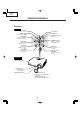
XV-Z2000 DT-400 THE OPTICAL UNIT OUTLINE Layout for proper setup of the optical components and parts (top view) (Schematic diagram) Reflection mirror Projection lens Color wheel Lamp Field lens DMD Rod UV Filter Illumination lenses 1 Illumination lenses 2 Item Lamp Color wheel Rod Illumination lenses Reflection mirror Field lens DMD Projection lens Function Light source. DC high-pressure mercury lamp. Splits light from the light source into R, G, B and W through a color filter.
XV-Z2000 DT-400 Air Flow After replacing the DMD, if shading is present on the screen as shown in Figure 1, adjust the lighting area of the DMD by turning the adjustment screws for the optical engine. 1. Loosen the fixing screw for the adjustment lever 1. Adjust the lighting area by adjustment lever 2 and then tighten the fixing screw for the adjustment lever 1. 2.
XV-Z2000 DT-400 ELECTRICAL ADJUSTMENT No. Adjusting point Adjusting conditions Adjusting procedure 1 Initialization of EEPROM 1. Turn on the power (the lamp lights up) and warm up the system for 15 minutes. 1. Carry out the following setting. Using the remote controller or press S2002 to enter the process mode, and execute SS2 on SS menu. 2 Adjustment of CW index 1. Input the gradation pattern of RGB. (SVGA60Hz or XGA) 2. S e l e c t t h e f o l l o w i n g group and subject.
XV-Z2000 DT-400 No. Adjusting point Adjusting conditions Adjusting procedure 3-3 B-Bright / BContrast 1. Group: AD Subject: B-BRIGHT (Black level) B-CONTRAST (White level) 2. Feed the window pattern signal containing 91% (0.64Vp-p) B signal and 0% level. (Process/Gamma interaction) (SVGA or XGA) Input 5 RGB input 1. Observe the 0% window pattern chromaticity on CA100. 2.
XV-Z2000 DT-400 No. Adjusting point Adjusting conditions Adjusting procedure 4-4 DTV B-Bright/ Contrast Adjustment 1. Group: DTV Subject: B-BRIGHT (Black level) B-CONTRAST (White level) (Process/GAMMA interaction Input5 Color difference input) 1. Observe the 0%black window pattern chromaticity on CA100. 2. Starting with a bit dropout screen, vary the Bright setting until the bright blue "y" setting turns toward the black tone and stays there.
XV-Z2000 DT-400 No. Adjusting point Adjusting conditions Adjusting procedure 13 DVD White balance (Auto adjustment) 1. Feed the component 75% gray scale signal. 2. Group: PIXEL Subject:R-GAIN (R) B-GAIN (B) Input 5 Color difference input 1. Adjust the white balance by controlling R-GAIN and B-GAIN. (Adjust x=298 and y=319.) 14 DLP voltage adjustment 1. Read the DLP-listed voltage rank. 2. Make the switch setting corresponding to the readout rank. (on the Formatter PWB) 1.
XV-Z2000 DT-400 * Precautions in setting up the DMD (Digital Micromirror Device) unit Before connecting the formatter PWB to the optical engine, take the following steps. Look at the voltage rank marking that is on the DMD itself. Referring to this marking, set the DIP switches on the formatter PWB. And connect this PWB to the optical engine. Wrong settings will adversely affect the system performance. Set the formatter PWB switches according to the Bin voltage shown on the back face of the DMD.
XV-Z2000 DT-400 Calling and quitting the process mode with the control keys on this model. ∗ Although it is possible for the process OUT to exit using the process menu, the IN/OUT toggle command is also available considering the existing specification. 1. Calling and quitting With the menu not displayed, press the "'", "'", """, """, "|", "\" and "ENTER" keys on main unit. 2. Others Press the S2002 process key (toggle) on the main PWB to call and quit the process menu.
XV-Z2000 DT-400 Adjustment mode process menu 2 second layer AD R-Bright G-Bright B-Bright R-Contrast G-Contrast B-Contrast EXIT DLP Index Delay R-Bright G-Bright B-Bright R-Contrast G-Contrast B-Contrast EXIT VIDEO1 N-Contrast P-Contrast S-Contrast Color NT3.58Delay NT4.
XV-Z2000 DT-400 TROUBLESHOOTING TABLE Checking the basic operation Does the power LED light up or flash in red or green? NO Go to "Checking the power supply system" and "Checking the power unit". NO Go to "Checking the peripheral circuits of the microprocessor". YES Does the set function with its keys or the remote controller? YES Does the cooling fan rotate, and the lamp turn on? NO Go to "Checking the lamp light-up".
XV-Z2000 DT-400 Checking the power supply system Is 13V outputted to pins (9) and (11) of P1707? NO Go to "Checking the power unit". YES Is 6V outputted to pins (1) and (3) of P1707? NO Go to "Checking the power unit". YES Is the connector of P1707 fully inserted? NO Is the voltage of 6V applied to both ends? Replace the thermal fuse. YES NO Check IC1707 and its peripheral circuits. Is B+5VA outputted from IC1707? YES NO Check IC1701 and its peripheral circuits.
XV-Z2000 DT-400 Checking the power unit Is each connector of the power unit fully inserted? NO Securely insert the connectors. YES Is the lamp door closed completely? NO Fix the lamp door with screws. YES Is the bimetal broken? NO Replace the bimetal switch or restore by pressing the red button. NO Replace F701. If other parts are damaged, replace them. NO Check D707 and the peripheral circuits of IC702 on the primary side. If defective, replace them.
XV-Z2000 DT-400 Checking the peripheral circuits of the microprocessor Are the voltages of approx. 3.3V and 2.5V applied to both ends of C8001 and C8056 respectively? NO Go to "Checking the power supply system". YES Are the oscillations of 133MHz and 74.25MHz outputted from pin (3) of X8003 and pin (3) of X8007 respectively? NO Check X8001, X8003 and their peripheral circuits. YES Does each terminal of R8038, R8039, R8041, R8042 and R8050 change? NO Check IC8202 or IC8001 is defective.
XV-Z2000 DT-400 Checking the lamp light-up Does each cooling fan function? NO Check the power supply circuit or fan circuit on the main circuit. YES Is the rotating sound of the color wheel heard? ABNORMAL NO YES Go to "Checking the peripheral circuits of the formatter". Check Q9401 to Q9403, IC9401(motor driver IC) and their peripheral circuits. NORMAL Replace the color wheel. Is the discharging sound heard? YES NO Is the lamp tight in the socket? NO Replace the lamp.
XV-Z2000 DT-400 » Formatter Unit Troubleshooting Display in trouble Screen with spectral colors Color production of R, G and B is not correct. Black screen Miscellaneous Equally spaced white or black vertical stripes Black horizontal band Adjustment by "Process Menu" →"DLP" → "INDEX". The failure state remains unchanged.
XV-Z2000 DT-400 Checking the digital input Input the digital signal from INPUT5. Select digital with the keys on the main body or the remote control. 1 YES Is picture outputted? YES NO Is the picture disturbed? End. NO Is the signal coming to pins (10)(77) of IC502? NO Check between the input terminals and IC502. NO Check IC8001 and its peripheral circuits. YES Is the signal coming to pins (26)(54) and (66)-(94) of SC2001? YES Check the Formatter unit.
XV-Z2000 DT-400 Checking the Component Send component signals to INPUT1 or INPUT2. Use keys on the main unit or remote control to select INPUT1 or INPUT2. YES Is video signal inputted into pins (3) to (5) of IC3102 at the time of INPUT1 selection, and is inputted into pins (15) to (17), respectively at the time of INPUT2 selection? NO Check IC3102 and its peripheral circuits. NO Check IC3102, IC3106 and their peripheral circuits. NO Check IC3104 and its peripheral circuits.
XV-Z2000 DT-400 Checking the Video Input Feed the composite video signal to INPUT 4. Select INPUT 4 using the set's key or the remote controller. End. 1 NO Does the picture appear? YES YES Is the picture disturbed? NO Is the video signal inputted to the pin (1) of IC3105? NO Check the VIDEO-IN signal line of Q3505. YES Check IC3504, IC3506 and their peripheral circuits.
XV-Z2000 DT-400 Checking the SOG Circuit Measure the pin (7) of IC5001 with an oscilloscope. YES Is the composite synchronized signal regenerated at proper timing? The SOG circuit is normal. End. NO Measure the pin (2) of Q5001 with an oscilloscope. Is there the Y signal including sync signal? NO Is there any output from the pin (25) of IC3102? YES YES This is the failure of the SOG synchronization separator circuit. 42 NO Check Q3110 and its peripheral circuits.
XV-Z2000 DT-400 Checking the S terminal input. Input the S terminal (Y, C) signal to INPUT 3. Select INPUT 3 with the keys on the main body or the remote controller. Does the picture appear? YES Is the picture disturbed? NO NO End. YES 1 Is the video signal inputted to the pins (43) and (44) of IC3105? NO YES Is the video signal outputted from pins (21), (22) and (23) of IC3105 inputted into pins (67), (68) and (69) of IC3102? YES Check the input side and its peripheral circuits.
XV-Z2000 DT-400 Checking the Sync Signal Is the horizontal synchronized signal on pin (6) of IC6003? NO YES Is the vertical synchronized signal on pin (6) of IC6009? NO Check the of the signal input part. YES Is the synchronized signal outputted from IC5009, IC5005, IC5006, IC5007 and IC5008? NO Check each IC and their peripheral circuits.
XV-Z2000 DT-400 Checking RS-232C Communication is disabled even though connecting the control PC and projector with a RS-232C cable. Is the connecting cable connected correctly? (cross cable) NO Replace the connecting cable. YES NO Is there any signal at pin (8) of IC8002? Check SC3501, R2039 and their peripheral circuits. YES NO Is there any signal at pin (106) of IC2201? Check IC2006 and its peripheral circuits. YES Check IC2002 and its peripheral circuits.
XV-Z2000 DT-400 Checking the IRIS, FOCUS and ZOOM motors Do all the motors function? YES Check the optical mechanism. NO Is 3.3V of IC8204 outputted as specified? NO Check the B+6V input line, IC8204 and its peripheral circuits. NO Check pins (16) and (17) of IC2002 and their peripheral circuits.
XV-Z2000 DT-400 TECHNISCHE DATEN Produkttyp Projector Modell XV-Z2000, DT-400 Videosystem PAL/PAL 60/PAL-M/PAL-N/SECAM/NTSC 3.58/NTSC 4.43 DTV 480I/480P/540P/576I/576P/720P/1080I Display-Verfahren Einzel-Bedienungsfeld-Digital Micromirror Device (DMDTM) von Texas Instruments DLP-Feld Feldformat: 0,8" Ansteuerungsmethode: Digital Light Processing (DLPTM) Anzahl der Punkte: 921.600 Punkte (1.
XV-Z2000 DT-400 HINWEISE FÜR DAS WARTUNGSPERSONAL 123456789012345678901234567890121234567890123456 123456789012345678901234567890121234567890123456 ACHTUNG: UV-STRAHLUNG 123456789012345678901234567890121234567890123456 123456789012345678901234567890121234567890123456 Die Beleuchtungsquelle des LCD-Projektors, eine UHP-Lampe, emittiert eine geringe Menge UV-Strahlung. DIREKTE BESTRAHLUNG AUF AUGEN UND HAUT MUSS VERMIEDEN WERDEN.
XV-Z2000 DT-400 Vorsichtsmaßregeln für bleifreien Lötzinn 1 Verwendung von bleifreiem Lötzinn Bei den Platinen für dieses Modells wird bleifreies Lot verwendet. Das Symbol LF kennzeichnet bleifreies Lot und findet sich an den Platinen und in den Wartungshandbüchern. Der Buchstabe hinter LF bezieht sich auf die Art des bleifreien Lots. Beispiel: LFa Zeigt bleifreien Lötzinn aus Zinn, Silber und Kupfer an. 2 Bei Reparatur der mit bleifreiem Lötzinn gelöteten Platine immer bleifreien Lötzinn verwenden.
XV-Z2000 DT-400 BEDIENUNGSANLEITUNG Projektor Draufsicht ON-Taste Schaltet die Stromversorgung ein. Netz-Anzeige STANDBY-Taste Lampen-Anzeige Schaltet den Projektor in den Standby-Modus. TemperaturwarnAnzeige RESIZE-Taste Für das Umschalten der Bildanzeige (STRECKEN, SEITENBALKEN, usw.). ZOOM/FOCUS-Taste Für das Einstellen der projizierten Bildgröße oder das Einstellen des Fokus. ENTER-Taste Für das Einstellen der ausgewählten oder eingestellten Menüpunkte.
XV-Z2000 DT-400 Informationen über die Anzeigen des Projektors Netz-Anzeige Rot leuchtend ... Normal (Standby) Grün leuchtend ... Normal (Eingeschaltet) Lampen-Anzeige Grün leuchtend ... Normal Grün blinkend ... Die Lampe wird aufgewärmt oder wird ausgeschaltet. Rot leuchtend ... Die Lampe wurde auf unnormale Weise ausgeschaltet oder muss ausgewechselt werden. Temperaturwarn-Anzeige Aus ... Normal Rot leuchtend ... Die Temperatur im Inneren des Gerätes ist zu hoch.
XV-Z2000 DT-400 Projektor (Rückansicht) Anschlüsse Beachten Sie die Erläuterungen unter „INPUT (EINGANG)-Anschlüsse und Hauptausrüstung zum Anschließen“ . INPUT 2-Anschluss Anschluss für Komponentensignale. INPUT 4-Anschluss Anschluss für ein Videogerät. INPUT 1-Anschluss Anschluss für Komponentensignale. INPUT 3-Anschluss Anschluss für ein Videogerät mit einem S-Video-Anschluss.
XV-Z2000 DT-400 Fernbedienung STANDBY-Taste Schaltet den Projektor in den Standby-Modus. ON-Taste Schaltet die Stromversorgung ein. KEYSTONE-Taste Für das Aktivieren des TrapezverzerrungsKorrekturmodus. MENU-Taste Für die Anzeige des Justierungs- und Einstellungsbildschirms. ENTER-Taste Einstelltasten ('/"/\/|) Für das Einstellen der ausgewählten oder eingestellten Menüpunkte. UNDO-Taste Für das Rückgängigmachen eines Bedienschrittes oder für die Rückkehr zur vorherigen Anzeige.
XV-Z2000 DT-400 Fernbedienungssensor Vorderansicht 30° Reichweite 30° Der Projektor kann mittels der Fernbedienung innerhalb der in der Abbildung dargestellten Bereiche gesteuert werden. Signalsender für Fernbedienung 7m 30° Hinweis • Das Signal von der Fernbedienung kann für eine einfache Bedienung von der Bildwand reflektiert werden. Die tatsächliche Reichweite des Signals kann je nach Bildwandmaterial unterschiedlich sein.
XV-Z2000 DT-400 Verbindungs-Pin-Zuweisungen DVI-I (INPUT 5)-Anschluss: 29-pol. Stecker • DVI-Digital-Eingang 9 ~ 16 ∞ ∞ ∞ ∞ ∞ ∞ ∞ ∞ ∞∞ ∞ ∞ ∞ ∞ ∞ ∞ ∞ ∞ 1 2 ~ ∞∞∞∞ 7 8 ∞∞∞∞ C1 C2 C4 C5 C3 17 24 18 ~ ∞ ∞ ∞ ∞ 23 ∞∞∞∞ Pin Nr. Signal 1 T.M.D.S.-Daten 22 T.M.D.S.-Daten 2+ 3 T.M.D.S.-Daten 2-Schutz 4 Nicht angeschlossen 5 Nicht angeschlossen 6 DDC-Takt 7 DDC-Daten 8 Nicht angeschlossen 9 T.M.D.S.-Daten 110 T.M.D.S.-Daten 1+ 11 T.M.D.S.
XV-Z2000 DT-400 ABMESSUNGEN Einheiten: mm Ansicht von hinten Ansicht von der Seite 1,5 Ansicht von oben 3,25 282 Ansicht von der Seite 310 5 55,5 89 Ansicht von vorne 48,5 55,05 99,95 129,5 129,5 29,1 30,9 M4 M4 M4 44,1 30,9 56 106,3 14 15,5 M4 225,3 210,3 Ansicht von unten
XV-Z2000 DT-400 ENTFERNEN DER HAUPTTEILE 1. Ausbau der Lampentür und der Lampeneinheit 1-1. Die Lampentür-Befestigungsschraube herausdrehen, dann die Lampentür abnehmen. 1-2. Die 2 Lampeneinheits-Befestigungsschrauben herausdrehen, dann die Lampeneinheit abheben. Lampeneinheit 1-3 Lampentür 1-2 2. Ausbau des oberen Gehäuses 2-1. Eine Postkarte oder ein dickes papier unter dem objektivtubus einzuführen. 2-2. Die 6 Befestigungsschrauben für das obere und das untere Gehäuse herausdrehen. 2-3.
XV-Z2000 DT-400 3. Anbringen der oberen Gehäuses (Für die geeigneten Schrauben ist auf den Abschnitt "2. Aubau des oberen Gehäuses" Bezug zu nehmen.) 3-1. Die Postkarte über dem Objektivtubus einführen. 3-2. Die obere Gehäuse aufsetzen. Sicherstellen, daß die vier Haken gut einrasten. 3-3. Die Postkarte wieder herausziehen. Oberes Gehäuse 3-2 Unteres Gehäuse 3-1 3-3 Dickes Papier wie z.B. eine Postkarte 4. Ausbau der Hauptleiterplatteneinheit und der peripheren Einheiten 4-1. 4-2. 4-3. 4-4. 4-5. 4-6.
XV-Z2000 DT-400 5. Ausbau der optischen Laufwerkeinheit 5-1. 5-2. 5-3. 5-4. 5-5. Die Befestigungsschrauben für die Halterung. Die zwei Sperrschrauben vom Lampenfassung entfernen. Die 5 Befestigungsschrauben für die optische Laufwerkeinheit herausdrehen. Den Kanal abnehmen. Die Lautsprecherhalter abnehmen. 5-2 Kanal 5-4 5-3 Optische Laufwerkeinheit 5-1 Halterung Lampenfassung 5-5 Lautsprecherhalter 5-3 6. Ausbau der Vorschaltgerät/Netz-Einheit 6-1.
XV-Z2000 DT-400 7. Ausbau der Vorschaltgerät/Netz-Einheit 7-1. 7-2. 7-3. 7-4. Die Befestigungsschraube für die hintere R/C-einheit herausdrehen. Die 4 Befestigungsschrauben, 4 WH-Naben und den Randhalter für die Vorschaltgerätteil entfernen. Die 11 Befestigungsschrauben und 5 WH-Naben für das Netzteil entfernen. Die 4 Befestigungsschrauben für das Gebläse herausdrehen.
XV-Z2000 DT-400 9. Befestigen der Erdungsplatte 9-1. 9-2. 9-3. 9-4. 9-5. 9-6. 9-7. 9-8. Die vier Muttern anbringen. Die Verstärkung (Halterung A) aufsetzen. Die Erdungsplatte wie gezeigt ansetzen. Die Verstärkung (Halterung B) aufsetzen. Die vier M3-Schrauben festziehen. Die vier M4-Schrauben festziehen. Die Erdungsplatte wie gezeigt ansetzen. Die sechs 17 der Erdungsplatte schmelzen.
XV-Z2000 DT-400 RÜCKSTELLUNG DES LAMPEN-TIMERS ● Rückstellung des Lampen-Timers Den Lampen-Timer nach dem Lampenaustausch zurückzustellen. Info • Stellen Sie sicher, dass Sie den Lampen-Timer nur nach dem Austausch der Lampe zurücksetzen. Wenn Sie den Lampen-Timer zurückstellen und dieselbe Lampe weiterhin verwenden, könnte die Lampe beschädigt werden oder explodieren. 1 2 Netzanschluss ON-Taste Das Netzkabel anschließen. ENTER-Taste • Das Netzkabel am Netzanschluss des Projektors anschließen.
XV-Z2000 DT-400 63
XV-Z2000 DT-400 BESCHREIBUNG DER OPTIK-EINHEIT Erläuterungen für das korrekte Setup der optischen Komponenten und Baugruppen (Ansicht von oben) (Schematische Darstellung) Reflektorspiegel Projektionslinse Farbrad Lampe Feldlinse DMD Stab UV-Filter Beleuchtungslinsen 1 Beleuchtungslinsen 2 Objekt Lampe Farbrad Stab Beleuchtungslinsen Reflektorspiegel Feldlinse DMD Projektionslinse Funktion Lichtquelle.
XV-Z2000 DT-400 Luftfluß Wenn nach dem Austausch von DMD eine Abschattung auf der Leinwand erscheint (siehe Abbildung 1), den Beleuchtungsbereich von DMD einstellen, indem man die Einstellschrauben für den optischen Motor dreht. 1. Die Befestigungsschraube für den Einstellhebel 1 lösen. Den Beleuchtungsbereich mit dem Einstellhebel 2 einstellen, dann die Befestigungsschraube für den Einstellhebel 1 anziehen. 2.
XV-Z2000 DT-400 ELEKTRISCHE EINSTELLUNG Nr. Einstellpunkt Einstellbedingungen Einstellverfahren 1 Initialisieren von EEPROM 1. DieBetriebsstromversorgung einschalten (die Lampe leuchtet auf), und das System 15 Minuten lang warmlaufen lassen. 1. Die folgende Einstellung ausführen. Das Fernbedienungsteil verwenden oder S2002 drücken, um auf Prozessmodus zu schalten, und SS2 im SS-Menü ausführen. 2 Einstellung von CW-Index 1. Gradationsmuster von RGB eingeben. (SVGA60Hz oder XGA) 2.
XV-Z2000 DT-400 Nr. Einstellpunkt Einstellbedingungen Einstellverfahren 3-2 G-Helligkeit/GKontrast 1. Gruppe: AD Gegenstand: G-BRIGHT (Schwarzpegel) G-CONTRAST (Weißpegel) 2. Das Fenstermustersignal mit einem Anteil von 91% (0,64 Vs-s) G-Signal und 0% Pegel. (Prozess/GammaInteraktion) (SVGA oder XGA) Eingang 5 RGB Eingang 1. D i e 0 % - F e n s t e r - C h r o m a t i k v o n C A 1 0 0 beobachten. 2.
XV-Z2000 DT-400 Nr. Einstellpunkt Einstellbedingungen Einstellverfahren 4-1 DTV-Helligkeit/ KontrastEinstellung 1. Gruppe: DTV Gegenstand:BRIGHT (Schwarzpegel) CONTRAST (Weißpegel) 1. Den festen Wert prüfen. Kontrast: 5 Helligkeit: 55 4-2 DTV-Helligkeit/ Kontrast 1. D a s 4 8 0 P 1 0 0 % / 0 % Schwarz/Weiß-FensterMustersignal anlegen. 2. Gruppe: DTV Gegenstand: R-BRIGHT (Schwarzpegel) R-CONTRAST (Weißpegel) (Prozess/GammaInteraktion) Eingang 5-Farb-Differenz Eingang 1.
XV-Z2000 DT-400 Nr. Einstellpunkt Einstellbedingungen Einstellverfahren 4-4 DTV-Helligkeit/ Kontrast 1. D a s 4 8 0 P 1 0 0 % / 0 % Schwarz/Weiß-FensterMustersignal anlegen. 2. Gruppe: DTV Gegenstand: B-BRIGHT (Schwarzpegel) B-CONTRAST (Weißpegel) (Prozess/GammaInteraktion) Eingang 5-Farb-Differenz Eingang 1. Die 0%-Schwarz-Fenster-Chromatik von CA100 beobachten. 2.
XV-Z2000 DT-400 Nr. Einstellpunkt Einstellbedingungen Einstellverfahren 11 VIDEO-Farbton 1. Gruppe: VIDEO Gegenstand: N-Farbton P-Farbton S-Farbton 1. Die festen Werte prüfen. N-Farbton: 8 P-Farbton: 4 S-Farbton: 4 12 VIDEOFarbsättigungspegel 1. Gruppe: VIDEO Gegenstand: N-Farbe P-Farbe S-Farbe 1. Die festen Werte prüfen. N-Farbe: 7 P-Farbe: 4 S-Farbe: 7 13 DVDWeißabgleich (automatische Einstellung) 1. Das Komponenten 75%Grauskalensignal einspeisen. 2.
XV-Z2000 DT-400 * Vorsichtsmaßregeln bei Einrichtung der DMD (Digital Micromirror Device)-Einheit Vor dem Anschließen der Formatierleiterplatte an der Optikengine die folgenden Schritte ausführen. Die Spannungsrangmarkierung am DMD selber beachten. Unter bezug auf diese Markierung die DIP-Schalter an der Formatierleiterplatte einstellen. Dann diese Leiterplatte an die Optikengine anschließen. Falsche Einstellungenbeeinträchtigen die Systemleistung.
XV-Z2000 DT-400 1. Aktivieren und Deaktivieren des Prozeßmodus unter Verwendung der Steuertasten dieses Modells. ∗ Für den Prozess OUT ist es möglich, unter dem Prozessmenü zu verlassen, jedoch ist auch der IN/OUTUmschaltbefehl mit Rücksicht auf die vorhandene Spezifikation verfügbar. 1. Aktivieren und Deaktivieren Bei nicht angezeigtem Menü die Tasten ""'", "'", """, """, "|", "\" und "ENTER" auf dem Hauptgerät drücken. 2.
XV-Z2000 DT-400 Prozeßmenü 2 2. Schicht AD R-Bright G-Bright B-Bright R-Contrast G-Contrast B-Contrast EXIT DLP Index Delay R-Bright G-Bright B-Bright R-Contrast G-Contrast B-Contrast EXIT VIDEO1 N-Contrast P-Contrast S-Contrast Color NT3.58Delay NT4.43Delay PAL Delay SECAM Delay Shapness2 EXIT PIXEL R-GAIN G-GAIN B-GAIN EXIT Pedestal R-Bright G-Bright B-Bright R-Contrast G-Contrast B-Contrast EXIT 2.
XV-Z2000 DT-400 FEHLERSUCHTABELLE Überprüfung der grund-legenden Funktionen Ist die POWER LED eingeschaltet, oder blinkt sie rot oder grün? NEIN Zu den Abschnitten "Überprüfen des Stromversorgungssystems" und "Überprüfen der Energieversorgung" gehen. JA Kann das Gerät mit der Einschalttaste oder NEIN über die Fernbedienungseinheit eingeschaltet werden? JA Mit dem Abschnitt "Überprüfung der peripheren Schaltkreise des Mikroprozessors" fortfahren.
XV-Z2000 DT-400 Überprüfung des Stromversorgungssystems Wird 13V dem Stift (9) und (11) von P1707 zugeführt? NEIN Mit dem Abschnitt "Überprüfung des Netzteils" fortfahren. NEIN Mit dem Abschnitt "Überprüfung des Netzteils" fortfahren. JA Wird 6 V dem Stift (1) und (3) von P1707 zugeführt? JA Ist der Anschluss von P1707 fest eingesetzt? Liegt 6 V an den beiden Enden an NEIN Die Temperatursicherung ersetzen. JA NEIN IC1707 und die peripheren Schaltkreise überprüfen.
XV-Z2000 DT-400 Überprüfen des Netzteils Sind die Anschlüsse des Netzteils fest eingesetzt? NEIN Den Anschluss fest einsetzen. JA Ist die Lampentür vollständig geschlossen? NEIN Die Lampentür vollständig mit Schrauben schließen. NEIN Den Bimetall-Schalter ersetzen oder die rote Taste zum Wiederherstellen drücken. JA Ist das Bimetall durchgebrannt? JA Liegt eine Wechselspannung an den beiden Enden des WechselstromEingangs von DB701 an? NEIN F701 ersetzen.
XV-Z2000 DT-400 Überprüfung der peripheren Schaltkreise des Mikroprozessors Liegen ca. 3,3 V und ca. 2,5 V an den beiden Enden von C8001 bzw. C8056 an? NEIN Mit dem Abschnitt "Überprüfung des Stromversorgungssystems" fortfahren. JA Werden die Oszillationen von 133 Hz und NEIN 74,25 Hz aus dem Stift (3) von X8003 und stift (3) von X8001 zugeführt? X8001, X8003 und die peripheren schaltkreise überprüfen.
XV-Z2000 DT-400 Überprüfung der Lampenfunktion Laufen die Kühlgebläse? NEIN Den Stromversorgungskreis oder GebläseSchaltkreis am Hauptschaltkreis überprüfen. JA Wird das Betriebsgeräusch des Farbrades gehört? FEHLERHAFT NEIN JA Q9401-Q9403, IC9401 (Motortriber-IC) und die peripheren schaltkreise überprüfen. Mit dem Abschnitt "Überprüfung der peripheren Schaltkreise des Formatters" fortfahren. NORMAL Das Farbrad auswechseln.
XV-Z2000 DT-400 » Formatiereinheit-Störungssuche Störung an Display Bildschirm mit Spektralfarben Farbproduktion bei R, G und B ist nicht korrekt. Schwarzer Bildschirm Einstellung mit "Prozessmenü"→"DLP" →"INDEX". Der Fehlerstatus bleibt unverändert. Gleichmäßig verteilte weiße oder schwarze senkrechte Streifen Schwarzer horizontaler Balken.
XV-Z2000 DT-400 Überprüfen des Digitaleingangs Das Digitalsignal vom INPUT5 zuführen. Das Digitalsignal mit den Tasten am Gerät oder auf der Fernbedienung anwählen. 1 JA Wird ein Bild ausgegeben? JA Liegen Bildstörungen vor? NEIN Ende NEIN Wird das Signal den Stiften (10)(77) von IC502 zugeführt? NEIN Zwischen den Eingangsanschlüssen und dem IC502 überprüfen. NEIN IC8001 und seine peripheren Schaltkreise überprüfen.
XV-Z2000 DT-400 Überprüfen der Komponenten Komponenten-Signale an INPUT1 oder INPUT2 weiterleiten. Die Tasten am Gerät oder auf der Fernbedienung benutzen, um INPUT1 oder INPUT2 anzuwählen. JA Wird das zum Zeitpunkt der INPUT1-Wahl den Stiften (3) bis (5) von IC3102 zugeführte NEIN Videosignal den Stiften (15) bis (17) zugeführt (zum Zeitpunkt der INPUT2-Wahl)? IC3102 und seine peripheren Schaltkreise überprüfen.
XV-Z2000 DT-400 Prüfen des Videoeingangs Das FBAS-Videosignal an INPUT4 einspeisen. INPUT4 mit den Tasten am Gerät oder an der Fernbedienung wählen. Ende. 1 NEIN JA Erscheint das Bild? JA Ist das Bild gestört? NEIN Liegt das videosignal an Stift (1) von IC3105 an? NEIN Die Signalleitung VIDEO-IN von Q3505 prüfen. JA IC3504, IC3506 und ihre Peripheriekreise prüfen. JA IC3501 und seine Peripheriekreise prüfen.
XV-Z2000 DT-400 Prüfen der SOG-Schaltung Den Stift (7) von IC5001 mit einem Oszilloskop prüfen. Wird das FBAS-Signal mit richtiger Zeitgabe regeneriert? JA Die SOG-Schaltung ist normal. Ende. NEIN Gibt es Ausgang von Stift (25) von IC3102? NEIN Den Stift (2) von Q5001 mit einem Oszilloskop prüfen. Ist das Y-Signal einschließlich SynSignal vorhanden? JA JA Dies ist ein Fehler in der SOGSynchronisationsSeparatorschaltung. 83 NEIN Q3110 und die peripheren Schaltkreise überprüfen.
XV-Z2000 DT-400 Prüfung des Eingangs der SKlemme. Das S-Klemmen-Signal (Y, C) von INPUT3 eingeben. INPUT3 mit den Tasten am Hauptgerät oder an der Fernbedienung wählen. JA Erscheint das Bild? Ist das Bild gestört? NEIN NEIN Ende. JA 1 Wird das Bildsignal an die Stifte (43) und (44) von IC3105? NEIN JA Werden die Videosignale von den Stiften (21), (22) und (23) von IC3105 ausgegeben und an Stifte (67), (68) und (69) von IC3102 angelegt? JA Die eingangsseitige Leiterplatte prüfen.
XV-Z2000 DT-400 Prüfen des Sync-Signals Wird das horizontal synchronisierte Signal auf Stift (6) von IC6003 ausgegeben? NEIN JA Wird das vertikal synchronisierte Signal auf Stift (6) von IC6009 ausgegeben? NEIN Die Leiterplatte des Signaleingangsteils prüfen. JA Wird das synchronisierte Signal von NEIN IC5009, IC5005, IC5006, IC5007 und IC5008 ausgegeben? Jeden IC und die Peripherieschaltung des ICs prüfen.
XV-Z2000 DT-400 Überprüfung von RS-232C Eine Kommunikation ist nicht möglich, selbst wenn der Steuer-PC und der Projektor mit einem RS-232C-Kabel verbunden werden. JA st das Anschlusskabel richtig angeschlossen? (Crosskabel) NEIN Das Anschlusskabel ersetzen. JA NEIN Empfängt der Stift (8) von IC2006 ein Signal? SC3501, R2039 und die peripheren Schaltkreise überprüfen. JA NEIN Empfängt der Stift (106) von IC2201 ein Signal? IC2006 und die peripheren Schaltkreise überprüfen.
XV-Z2000 DT-400 Überprüfen des Blenden-, Fokus- und Zoommotors Funktionieren alle Motoren? JA Den Optik-Mechanismus überprüfen. NEIN Liegen am IC8204 3,3 V an, wie spezifiziert? NEIN Die B+6V-Eingangsleitung, den IC8204 und seine peripheren Schaltkreise überprüfen. JA Liegt das I2C-Signal an den Stiften (2) und (3) von IC8201 an? NEIN Die Stifte (16) und (17) von IC2002 und ihre peripheren Schaltkreise überprüfen.
XV-Z2000 DT-400 BLOCK DIAGRAM/BLOCK SCHALTBILD H EXHAUST FAN1 LAMP BLOW FAN EXHAUST FAN2 THERMISTOR POWER FAN ZOOM M FRONT R/C DUNTKC754WEF* IRIS M FOCUS M REAR R/C DUNTKC755WEF* FAN ERROR G FAN3 REG IC1710 PQ20WZ11 KEY LED FAN1 REG IC1708 PQ20WZ11 FAN2 REG IC1709 PQ20WZ11 FAN4 REG IC1711 PQ20WZ11 ZOOM/FOCUS IC8205 LB1831M IRIS DRIVE IC8206 LB1638M 3.3 REG IC8204 PQ1L333M I/ O IC8201 M62320FP DA IC5014 M62334FP 14.
XV-Z2000 DT-400 BALLAST UNIT RDENCA088WJZZ LAMP COLOR WHEEL SENSOR SENSOR ZOOM LAMP_EN ECO/LPS M IGNITER DC-DC LAMP_LIT RIS M FOCUS M SECONDARY PRIMARY BI-METAL 6V PRIMARY SECONDARY ZOOM/FOCUS IC8205 LB1831M S DRIVE C8206 1638M DC-DC 13V 3. 3V PFC PFC-ON/OFF PCON0 LAMP-DOOR SW ECO/LPS FP LAMP_EN POWER UNITRDENCA082WJZZ B+6V LAMP_LITC B+13V LINE FILTER 5V REG IC1704 Q050DZ1 12V REG IC1705 PQ12DZ1 U C-DC 3.3V IC1713 MP1410E S 9V REG IC1706 PQ09DZ1 U PFC-ON/OFF AC CORD C-DC 2.
XV-Z2000 DT-400 OVERALL WIRING DIAGRAM/GESAMTSCHALTPLAN H ZOOM/FOCUS MOTOR RMOTBA005WJZZ LAMP FAN NFANSA017WJZZ POWER FAN EXHAUST FAN1 EXHAUST FAN2 NFANSA035WJZZ NFANSA034WJZZ IRIS MOTOR ZOOM MOTOR RMOTBA006WJZZ P1704 FC L O C K 4 + B 1 G N D 2 N C 3 B 1 + P1705 FD G N D 2 L O C K 3 L O C K 4 + B 1 G N D 2 N C 3 B 1 4 + 3 P1706 P8201 AI G N D 2 L O C K 3 2 F O C U S 1 P1706 Z O O M - Z O O M + B 1 + G N D 2 L O C K 3 G F O C U S + FOCUS MOTOR IRIS MOTOR P1703 FB FA
XV-Z2000 DT-400 COLOR WHEEL CFILWA081WJ0 1 N C 4 1 ) U 3 ) U 2 ) U ( ( P2004 ( FA 1 5V 5V 12 0 M O Y 3 P1703 M O Y 2 C W M O Y 1 1 V 5 2 G N D 3 PHOTO SENSOR UNIT RUNTKA091WJZZ B + 4 L O C K + B 1 G N D 2 N C 3 NFANSA034WJZZ N D E X EXHAUST FAN2 2 GND GND 11 9 3 GND GND 11 8 4 12V 12V 11 7 5 12V 12V 11 6 P2003 CW 6 GND DD 11 5 7 3.3V 3.3V 11 4 8 3.3V 3.3V 11 3 9 GND GND 11 2 10 GND 2.5V 11 1 11 2.5V 2.5V 11 0 12 2.5V 2.
XV-Z2000 DT-400 WAVEFORMS / WELLENFORMEN 1 IC3102 (28) pin (VS-OUT) H : 5m sec/div V : 1V/div 2 IC3102 (29) pin (HS-OUT) H : 20µ sec/div V : 1V/div 3 IC3102 (31) pin (SCP-IN) H : 20µ sec/div V : 1V/div 4 IC3102 (35) pin (3YO) H : 20µ sec/div V : 1V/div 5 IC3102 (37) pin (2YO) H : 20µ sec/div V : 1V/div 6 IC3102 (39) pin (1YO) H : 20µ sec/div V : 1V/div 7 IC3105 (43) pin (C2-IN) H : 20µ sec/div V : 1V/div 8 IC3105 (44) pin (CVBS/Y2-IN) H : 20µ sec/div V : 1V/div 9 IC3506 (7) pin (YCIN) H : 20µ sec/
XV-Z2000 DT-400 H PRINTED WIRING BOARD ASSEMBLIES LEITERPLATTENEINHEITEN G F FRONT R/C Unit (Side-A)/ Vordere R/C-Einheit (Seite-A) FRONT R/C Unit (Side-B)/ Vordere R/C-Einheit (Seite-B) REAR R/C Unit (Side-A)/ Hintere R/C-Einheit (Seite-A) REAR R/C Unit (Side-B)/ Hintere R/C-Einheit (Seite-B) E D C B A 1 2 3 4 93 5 6
XV-Z2000 DT-400 H G F E D C B A MAIN Unit (Side-A) HAUPT-Einheit (Seite-A) 1 2 3 4 5 6 94 7 8 9 10
XV-Z2000 DT-400 10 11 12 13 14 15 95 16 17 18 19
XV-Z2000 DT-400 H G F E D C B A MAIN Unit (Side-B) HAUPT-Einheit (Seite-B) 1 2 3 4 5 6 96 7 8 9 10
XV-Z2000 DT-400 10 11 12 13 14 15 97 16 17 18 19
XV-Z2000 DT-400 H G F E D C B A FORMATTER Unit (Side-A) FORMATTER-Einheit (Seite-A) 1 2 3 4 98 5 6
XV-Z2000 DT-400 H G F E D C B A FORMATTER Unit (Side-B) FORMATTER-Einheit (Seite-B) 1 2 3 4 99 5 6
XV-Z2000 DT-400 H G F E D C B A POWER Unit (Side-A) NETZ-Einheit (Seite-A) 1 2 POWER Unit (Side-B) NETZ-Einheit (Seite-B) 3 4 100 5 6
XV-Z2000 DT-400 Ref. No. Part No. ★ Description PARTS LIST Code Ref. No. ★ Part No. Description Code ERSATZTEILLISTE PARTS REPLACEMENT AUSTAUSCH VON TEILEN Parts marked with "å" are important for maintaining the safety of the set. Be sure to replace these parts with specified ones for maintaining the safety and performance of the set. Ersatzteile, die besondere Sicherheitseigenschften haben, sind in dieser Anleitung markiert.
XV-Z2000 DT-400 Ref. No. ★ Part No.
XV-Z2000 DT-400 Ref. No. ★ Part No.
XV-Z2000 DT-400 Ref. No. Part No. ★ Description Code Ref. No.
XV-Z2000 DT-400 Ref. No. ★ Part No.
XV-Z2000 DT-400 Ref. No. Part No. ★ Description Code Ref. No.
XV-Z2000 DT-400 Ref. No. Part No. ★ Description Code Ref. No.
XV-Z2000 DT-400 Ref. No. ★ Part No.
XV-Z2000 DT-400 Ref. No. ★ Part No. Description Code Ref. No. ★ Part No. Description DUNTKC754WEF0 DUNTKC757WEF0 FRONT-R/C UNIT FORMATTER UNIT CAPACITORS C1551 VCKYCY1EF104ZY J 0.
XV-Z2000 DT-400 Ref. No. Part No.
XV-Z2000 DT-400 Ref. No. ★ Part No.
XV-Z2000 DT-400 Ref. No. ★ Part No. Description Code RDENCA082WJZZ Ref. No.
XV-Z2000 DT-400 Ref. No. Part No. ★ Description Code RDENCA082WJZZ POWER UNIT(Continued) 9FJ0G20003190 9FJ0S97403300 9FJ0S89000180 9FJ0S09703060 9FJ0S99403100 9FJ0S99403080 9FJ0S03703060 9FJ0S08303080 9FJ0S07703080 J J J J J J J J J Locking Card Spacer Screw, Fan Screw Screw Screw Screw Screw Screw Screw AD AD AC AB AB AB AB AC AB 113 Ref. No. Part No.
XV-Z2000 DT-400 Part No. ★ Description Code Ref. No. Part No. CABINET AND MECHANICAL PARTS ★ Ref. No.
XV-Z2000 DT-400 Ref. No. Part No.
XV-Z2000 DT-400 Part No. ★ Description Code Ref. No. OPTICAL MECHANISM PARTS Ref. No. H ★ Part No.
XV-Z2000 DT-400 Ref. No. Part No.
XV-Z2000 DT-400 Ref. No. Part No. ★ Description Code Ref. No. X1 å X1 å X1 å X1 X2 X3 X4 X5 X6 X6 X6 X6 X7 Description Code PACKING PARTS SUPPLIED ACCESSORIES å ★ Part No. (NOT REPLACEMENT ITEM) QACCBA036WJPZ J Power Cord(XV-Z2000,for U.K, AX Hong Kong and Singapore) QACCDA007WJPZ J Power Cord(XV-Z2000, for AR U.S.A, Canada and DT-400) QACCLA018WJPZ J Power Cord(XV-Z2000, for AU Australia and New Zealand) QACCVA011WJPZ J Power Cord(XV-Z2000, for AT Europe except U.
XV-Z2000 DT-400 Part No. ★ Description Ref. No. Part No. ★ Description PACKING OF THE SETCode / VERPACKEN DES GERÄTS Ref. No.
SCHEMATIC DIAGRAM SCHEMATISCHER SCHALTPLAN MODELS MODELLE XV-Z2000 DT-400 CONTENTS Page DESCRIPTION OF SCHEMATIC DIAGRAM …………………………………………………… D2 MAIN Unit …………………………………………………………………………………… D3 ∼ D20 FORMATTER UNIT …………………………………………………………………………D21 ∼ D32 POWER UNIT ………………………………………………………………………………D33 ∼ D34 R/C FRONT UNIT ………………………………………………………………………………… D35 R/C REAR UNIT …………………………………………………………………………………… D35 D1
DESCRIPTION OF SCHEMATIC DIAGRAM BESCHREIBUNG DES SCHEMATISCHEN SCHALTPLANS VOLTAGE MEASUREMENT CONDITION: SPANNUNGSMESSUNGEN: 1. Voltages at test points are measured at the supply voltage of AC 220V. Signals are fed by a color bar signal generator for servicing purpose and the above voltages are measured with a 20k ohm/V tester. 1.
ËMAIN UNIT / HAUPTEINHEIT-1/9 H G F E D C B A 1 2 3 4 5 6 D3 7 8 9 10
10 11 12 13 14 15 D4 16 17 18 19
ËMAIN UNIT / HAUPTEINHEIT-2/9 H G F E D C B A 1 2 3 4 5 6 D5 7 8 9 10
10 11 12 13 14 15 D6 16 17 18 19
ËMAIN UNIT / HAUPTEINHEIT-3/9 H G F E D C B A 1 2 3 4 5 6 D7 7 8 9 10
10 11 12 13 14 15 D8 16 17 18 19
ËMAIN UNIT / HAUPTEINHEIT-4/9 H G F E D C B A 1 2 3 4 5 6 D9 7 8 9 10
10 11 12 13 14 15 D10 16 17 18 19
ËMAIN UNIT / HAUPTEINHEIT-5/9 H G F E D C B A 1 2 3 4 5 6 D11 7 8 9 10
10 11 12 13 14 15 D12 16 17 18 19
ËMAIN UNIT / HAUPTEINHEIT-6/9 H G F E D C B A 1 2 3 4 5 6 D13 7 8 9 10
10 11 12 13 14 15 D14 16 17 18 19
ËMAIN UNIT / HAUPTEINHEIT-7/9 H G F E D C B A 1 2 3 4 5 6 D15 7 8 9 10
10 11 12 13 14 15 D16 16 17 18 19
ËMAIN UNIT / HAUPTEINHEIT-8/9 H G F E D C B A 1 2 3 4 5 6 D17 7 8 9 10
10 11 12 13 14 15 D18 16 17 18 19
ËMAIN UNIT / HAUPTEINHEIT-9/9 H G F E D C B A 1 2 3 4 5 6 D19 7 8 9 10
10 11 12 13 14 15 D20 16 17 18 19
ËFORMATTER UNIT / FORMATTER-EINHEIT-1/6 H G F E D C B A 1 2 3 4 5 6 D21 7 8 9 10
10 11 12 13 14 15 D22 16 17 18 19
ËFORMATTER UNIT / FORMATTER-EINHEIT-2/6 H G F E D C B A 1 2 3 4 5 6 D23 7 8 9 10
10 11 12 13 14 15 D24 16 17 18 19
ËFORMATTER UNIT / FORMATTER-EINHEIT-3/6 H G F E D C B A 1 2 3 4 5 6 D25 7 8 9 10
10 11 12 13 14 15 D26 16 17 18 19
ËFORMATTER UNIT / FORMATTER-EINHEIT-4/6 H G F E D C B A 1 2 3 4 5 6 D27 7 8 9 10
10 11 12 13 14 15 D28 16 17 18 19
ËFORMATTER UNIT / FORMATTER-EINHEIT-5/6 H G F E D C B A 1 2 3 4 5 6 D29 7 8 9 10
10 11 12 13 14 15 D30 16 17 18 19
ËFORMATTER UNIT / FORMATTER-EINHEIT-6/6 H G F E D C B A 1 2 3 4 5 6 D31 7 8 9 10
10 11 12 13 14 15 D32 16 17 18 19
ËPOWER UNIT / NETZTEILEINHEIT H G F E D C B A 1 2 3 4 5 6 D33 7 8 9 10
10 11 12 13 14 15 D34 16 17 18 19
ËR/C FRONT UNIT H G F E ËR/C REAR UNIT D C B A 1 2 3 4 D35 5 6
H G F E D C B A 1 2 3 4 5 6
XV-Z2000 DT-400 COPYRIGHT © 2005 BY SHARP CORPORATION ALL RIGHTS RESERVED. No part of this publication may be reproduced, stored in a retrieval system, or transmitted in any form or by any means, electronic, mechanical, photocopying, recording, or otherwise, without prior written permission of the publisher. TQ1839-S Jan. 2005 Printed in Japan Design and Production Information Design : Japan Production : China MY.